US4217536A - Supply voltage monitoring device for automotive battery - Google Patents
Supply voltage monitoring device for automotive battery Download PDFInfo
- Publication number
- US4217536A US4217536A US05/899,225 US89922578A US4217536A US 4217536 A US4217536 A US 4217536A US 89922578 A US89922578 A US 89922578A US 4217536 A US4217536 A US 4217536A
- Authority
- US
- United States
- Prior art keywords
- battery
- supply voltage
- output
- light emitting
- voltage
- Prior art date
- Legal status (The legal status is an assumption and is not a legal conclusion. Google has not performed a legal analysis and makes no representation as to the accuracy of the status listed.)
- Expired - Lifetime
Links
Images


Classifications
-
- G—PHYSICS
- G01—MEASURING; TESTING
- G01R—MEASURING ELECTRIC VARIABLES; MEASURING MAGNETIC VARIABLES
- G01R19/00—Arrangements for measuring currents or voltages or for indicating presence or sign thereof
- G01R19/165—Indicating that current or voltage is either above or below a predetermined value or within or outside a predetermined range of values
- G01R19/16533—Indicating that current or voltage is either above or below a predetermined value or within or outside a predetermined range of values characterised by the application
- G01R19/16538—Indicating that current or voltage is either above or below a predetermined value or within or outside a predetermined range of values characterised by the application in AC or DC supplies
- G01R19/16542—Indicating that current or voltage is either above or below a predetermined value or within or outside a predetermined range of values characterised by the application in AC or DC supplies for batteries
-
- F—MECHANICAL ENGINEERING; LIGHTING; HEATING; WEAPONS; BLASTING
- F25—REFRIGERATION OR COOLING; COMBINED HEATING AND REFRIGERATION SYSTEMS; HEAT PUMP SYSTEMS; MANUFACTURE OR STORAGE OF ICE; LIQUEFACTION SOLIDIFICATION OF GASES
- F25D—REFRIGERATORS; COLD ROOMS; ICE-BOXES; COOLING OR FREEZING APPARATUS NOT OTHERWISE PROVIDED FOR
- F25D29/00—Arrangement or mounting of control or safety devices
- F25D29/006—Safety devices
-
- G—PHYSICS
- G01—MEASURING; TESTING
- G01R—MEASURING ELECTRIC VARIABLES; MEASURING MAGNETIC VARIABLES
- G01R31/00—Arrangements for testing electric properties; Arrangements for locating electric faults; Arrangements for electrical testing characterised by what is being tested not provided for elsewhere
- G01R31/005—Testing of electric installations on transport means
- G01R31/006—Testing of electric installations on transport means on road vehicles, e.g. automobiles or trucks
-
- H—ELECTRICITY
- H02—GENERATION; CONVERSION OR DISTRIBUTION OF ELECTRIC POWER
- H02J—ELECTRIC POWER NETWORKS; CIRCUIT ARRANGEMENTS OR SYSTEMS FOR SUPPLYING OR DISTRIBUTING ELECTRIC POWER; SYSTEMS FOR STORING ELECTRIC ENERGY
- H02J7/00—Circuit arrangements for charging or discharging batteries or for supplying loads from batteries
- H02J7/14—Circuit arrangements for charging or discharging batteries or for supplying loads from batteries for charging batteries from dynamo-electric generators driven at varying speed, e.g. on vehicle
-
- H—ELECTRICITY
- H02—GENERATION; CONVERSION OR DISTRIBUTION OF ELECTRIC POWER
- H02J—ELECTRIC POWER NETWORKS; CIRCUIT ARRANGEMENTS OR SYSTEMS FOR SUPPLYING OR DISTRIBUTING ELECTRIC POWER; SYSTEMS FOR STORING ELECTRIC ENERGY
- H02J7/00—Circuit arrangements for charging or discharging batteries or for supplying loads from batteries
- H02J7/80—Circuit arrangements for charging or discharging batteries or for supplying loads from batteries including monitoring or indicating arrangements
-
- Y—GENERAL TAGGING OF NEW TECHNOLOGICAL DEVELOPMENTS; GENERAL TAGGING OF CROSS-SECTIONAL TECHNOLOGIES SPANNING OVER SEVERAL SECTIONS OF THE IPC; TECHNICAL SUBJECTS COVERED BY FORMER USPC CROSS-REFERENCE ART COLLECTIONS [XRACs] AND DIGESTS
- Y10—TECHNICAL SUBJECTS COVERED BY FORMER USPC
- Y10S—TECHNICAL SUBJECTS COVERED BY FORMER USPC CROSS-REFERENCE ART COLLECTIONS [XRACs] AND DIGESTS
- Y10S320/00—Electricity: battery or capacitor charging or discharging
- Y10S320/18—Indicator or display
- Y10S320/21—State of charge of battery
Definitions
- This invention relates generally to a supply voltage monitoring device for automotive battery, and more specifically to a supply voltage monitoring device for automotive battery which produces the average voltage of the supply voltage of an automotive battery to control the supply voltage of the battery by the light emitting state or the non-emitting state of a light emitting diode controlled by the average voltage.
- (A) is a characteristic curve representing the relationship between the d-c input voltage and the cooling capability
- (B) is a characteristic curve representing the relationship between the d-c input voltage and the a-c output voltage of the inverter
- (C) a characteristic curve representing the relationship between the d-c input voltage and the a-c output current of the inverter.
- Devices for monitoring the terminal voltage of a battery, etc. using light emitting diodes have been employed for this purpose.
- the supply voltage of an automotive battery as described above often undergoes great changes due to variations in the battery load during running, and particularly sharp kick-like voltage variations at the start of the starter.
- FIG. 1 is a graphical representation showing the characteristic of the d-c input voltage and the output of a vibration type electric refrigerator.
- FIG. 2 is a schematic diagram showing a battery supply voltage monitoring device embodying this invention used for controlling the cooling state of a vibration type electric refrigerator.
- FIG. 3 is a circuit diagram illustrating the construction of a battery supply voltage monitoring device embodying this invention.
- FIGS. 4 and 5 are circuit diagrams illustrating the constructions of other embodiments of this invention.
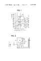
- FIGS. 6A and 6B are front and side views of a 2-door type electric refrigerator incorporating a voltage monitoring device of this invention.
- FIGS. 7A and 7B are front and side views of a 1-door type electric refrigerator incorporating a voltage monitoring device of this invention.
- FIGS. 8A and 8B are front and side views of a small electric refrigerator incorporating a voltage monitoring device of this invention.
- numeral 1 refers to a battery, 2 to a feed wire, 3 to an electric refrigerator, 4 to a refrigerating chamber, 5 to an inverter, 6 to a vibration type motor, 7 to a compressor, 8 to a condenser, 9 to an evaporator and 10 to a battery supply voltage monitoring device, respectively.
- the electric refrigerator 3 is connected over the feed wire 2 to the battery 1.
- the d-c power supplied from the battery 1 is converted into an alternating current in the inverter 5 to drive the vibration type motor 6 which in turn drives the compressor 7.
- Refrigerant compressed by the compressor 7 and condensed by the condenser 8 takes heat away from the refrigerating chamber 4 through vaporization in the evaporator 9 to cool the refrigerating chamber 4.
- the refrigerant evaporated in the evaporator 9 is fed back to the compressor 7 for compression. In this way, the compressor 7 is operated to maintain the temperature in the refrigerating chamber 4 within the prescribed temperature range.
- the battery supply voltage monitoring device 10 is constructed so as to average the battery supply voltage and to indicate a drop in the average voltage below the desired voltage level through visual and/or audio alarms.
- FIG. 3 shows a battery supply voltage monitoring device embodying the present invention.
- numeral 11 refers to the positive terminal of a battery, 12 to the negative terminal of the battery, 13 to a diode, 14 to an average voltage generation circuit, 15 through 21 to resistors, 22 and 23 to capacitors, 24 through 27 to transistor, 28 to a Zener diode, 29 to a light emitting diode, 30 to a switch and 31 to a buzzer, respectively.
- the battery terminal voltage across the terminals 11 and 12 is inputted to the average voltage generation circuit 14.
- the diode 13 is connected to the positive side for circuit protection in an accidental connection of the terminals 11 and 12 in reversed polarity.
- the average voltage of its input that is, the battery terminal voltage can be outputted by adequately selecting the parameters of the resistors 15, 16, 17 and the capacitor 22 to obtain a suitable time constant of the circuit.
- the average voltage generation circuit 14 can output an average voltage by smoothing voltage variations in the battery terminal voltage caused by variations in the load. Furthermore, the circuit 14 smoothes most part of kick-like voltage variations caused at the start of the starter or due to an instantaneous sharp change in the load to produce an output with minimal variations.
- the ratio of the resistance values of the resistors 15 and 16 and the resistor 17 is properly selected and the Zener diode 28 is connected via the first transistor 24 so that the Zener diode 28 conducts to permit the output voltage to pass when the input, or the battery terminal voltage exceeds the prescribed monitoring voltage value. This eliminates an adverse effect on the time constant of the average voltage generation circuit 14 when the Zener diode 28 is turned on. When the battery terminal voltage exceeds the monitoring voltage value, the Zener diode 28 conducts via the first transistor 24 connected to the output of the average voltage generation circuit 14, causing the second transistor 25 to conduct.
- the third transistors 26 and 27 are in the OFF state, and the light emitting diode 29 is also in the OFF state. This means that the light emitting diode 29 does not light up. In other words, the state where the light emitting diode does not light represents the state the battery terminal voltage is maintained at the prescribed monitoring voltage level.
- the output of the average voltage generation circuit 14 accordingly drops below the Zener voltage of the Zener diode 28, bringing the Zener diode 28 to the OFF state, and the first and second transistors 24 and 25 to the OFF state.
- the collector potential of the second transistor 25 is raised to initiate the charging of the capacitor 23.
- the base voltage of the third transistor 26 also rises, and the third transistors 26 and 27 are brought to the ON state.
- the transistors 26 and 27 are turned on, the light emitting diode 29 is turned on to light up.
- the buzzer 31 begins operating to indicate the lighted state of the light emitting diode 29.
- the state where the light emitting diode 29 lights up represents the state where the battery terminal voltage drops below the prescribed monitoring voltage level.
- the second transistor 25 is brought to the OFF state, causing the collector voltage of the transistor 25 to rise, the third transistors 26 and 27 do not come to operate due to the delay effect of the capacitor 23. Consequently, the light emitting diode 29 is not actuated by an instantaneous change in the battery terminal voltage. This means that the device of this invention monitors only the steady state voltage drop of the battery.
- FIG. 4 illustrates another embodiment of the battery supply voltage monitoring device of this invention.
- provision is made to change over the connection of the light emitting diode 29 from the output circuit of the second transistor 25 to the output circuit of the third transistor 27 with a change-over switch.
- numerals 11 through 31 correspond with the like numerals in FIG. 3, and numeral 32 refers to a changeover switch.
- the connection of the light emitting diode 29 can be changed over from the output circuit of the second transistor 25 to the output circuit of the third transistors 26 and 27 with the changeover switch 32 while the light emitting diode 29 is fixedly connected to the output of the third transistors 26 and 27 in FIG. 3.
- the changeover switch 32 is in the state shown in FIG. 4
- the light emitting diode 29 is connected to the output circuit of the third transistors 26 and 27.
- the circuit in the figure performs exactly the same operation as that shown in FIG. 3.
- the changeover switch 32 is thrown to the opposite side to the side shown in FIG. 4, the light emitting diode 29 is connected to the output circuit of the second transistor 25.
- the light emitting diode 29 is turned on to emit light when the second transistor 25 is in the ON state.
- the state where the light emitting diode 29 is in the light emitting state represents the state where the battery terminal voltage is maintained above the prescribed voltage level, since the operation of the circuit itself is the same as that shown in FIG. 3.
- FIG. 5 illustrates still another embodiment of the battery supply voltage monitoring device of this invention, where a switching circuit is provided to switch the load on or off to the output side of the battery supply voltage monitoring device.
- numeral 33 refers to a switching circuit
- symbols ⁇ and ⁇ refer to the signal output terminals of the third transistors 26 and 27 for external connection.
- Other numerals and symbols correspond with the like numerals and symbols in FIGS. 2 and 3.
- the third transistors 26 and 27 are maintained in the OFF state and a positive potential is applied to the gate G of the transistor 40. Consequently, the transistor 40 is maintained in the ON state, and the transistors 41 and 42 are also maintained in the ON state, thus permitting power to be fed to the inverter circuit 5.
- the light emitting diode 29 is in the OFF state, or the non-light-emitting state and the buzzer 31 is in the OFF state or the inoperative state.
- the third transistors 26 and 27 are brought to the ON state, reducing the potential at the gate G of the transistor 40 to almost zero and bringing the transistor 40 to the OFF state. This causes the transistors 41 and 42 to turn off, interrupting the power supply to the inverter circuit 5.
- the light emitting diode 29 is turned to the ON state to emit light, and the buzzer 31 is also brought to the ON state when the switch 30 is in the ON state.
- the capacitor 43 has functions to smooth the variations of the battery terminal voltage and to absorb the reactive current component from the output side of the inverter circuit 5, that is, the refrigerator side.
- the battery terminal voltage can be easily monitored by installing the battery supply voltage monitoring device 10, as described above, at a conspicuous position on a refrigerator to facilitate observation from the outside of the refrigerator as shown in FIGS. 6A, 6B, 7A, 7B, 8A and 8B.
- Numerals 7, 8 and 10 in the figure correspond with like numerals in FIG. 2, and numeral 44 refers to an outer casing of an electric refrigerator.
- the device of this invention can be installed, for example, on a lower part of the outer casing with screws or other suitable fasteners.
- a 1-door type refrigerator it can be installed on part of the door, as shown in FIGS. 7A and 7B.
- a small lidded refrigerator with a removable refrigerating box as shown in FIGS. 8A and 8B, which is used as an ice box or a fish container in sport fishing, it can be installed on part of the outer casing.
- the monitoring device of this invention can be made of very small size by incorporating integrated circuits, so it can be installed on a small space with screws or other simple fasteners.
- a drop in the input average voltage of a battery-powered refrigerator installed away from the battery can be externally detected, displayed or warned by installing the battery supply voltage monitoring device of this invention on part of the refrigerator.
- this simple device can eliminate a failure to notice the deteriorated cooling effect due to a voltage drop.
- a voltage drop can be immediately detected, displayed or warned, and prompt and adequate countermeasures can be taken.
- the same effect can be achieved by installing the battery supply voltage monitoring device of this invention at a power receptacle exclusively used for the refrigerator.
Landscapes
- Engineering & Computer Science (AREA)
- Physics & Mathematics (AREA)
- Power Engineering (AREA)
- Chemical & Material Sciences (AREA)
- Combustion & Propulsion (AREA)
- General Physics & Mathematics (AREA)
- Mechanical Engineering (AREA)
- Thermal Sciences (AREA)
- General Engineering & Computer Science (AREA)
- Measurement Of Current Or Voltage (AREA)
Abstract
A supply voltage monitoring device for an automotive battery comprising an average voltage generation circuit for generating the average voltage of the supply voltage of a battery as a power source for various equipment on board an automobile, a Zener diode conducting when the output voltage of the average voltage generation circuit exceeds the prescribed value, a first transistor connected between the Zener diode and the average voltage generation circuit, a second transistor controlled by the conducting Zener diode, a capacitor controlled for charging and discharging by the output of the second transistor, third transistors controlled by the output voltage of the capacitor, and a light emitting diode controlled for the light emitting state or the non-emitting state by the second transistor or the third transistors, and characterized in that the device is constructed to monitor the supply voltage of the battery by the light emitting state or the non-emitting state of the light emitting diode.
Description
1. Field of the Invention
This invention relates generally to a supply voltage monitoring device for automotive battery, and more specifically to a supply voltage monitoring device for automotive battery which produces the average voltage of the supply voltage of an automotive battery to control the supply voltage of the battery by the light emitting state or the non-emitting state of a light emitting diode controlled by the average voltage.
2. Description of the Prior Art
In recent years, an increasing number of d-c-powered electric refrigerators, for example, battery-powered electric refrigerators on board a car or a boat, etc. have been used. In these electric refrigerators, cooling is effected by taking heat away from the surroundings by means of refrigerant evaporated in the evaporator. The evaporated refrigerant is recovered and compressed in a compressor for recirculation. To drive the compressor, a vibration type motor, called swing motor, is often used. Since an alternating current is required to drive the vibration type motor, an inverter is used to convert the direct current of the battery into an alternating current. The output characteristic of the refrigerator with respect to the input voltage of the inverter, that is, the output voltage of the battery can be expressed as shown in FIG. 1, for example. In FIG. 1, (A) is a characteristic curve representing the relationship between the d-c input voltage and the cooling capability, (B) is a characteristic curve representing the relationship between the d-c input voltage and the a-c output voltage of the inverter, and (C) a characteristic curve representing the relationship between the d-c input voltage and the a-c output current of the inverter. As is evident from FIG. 1, the a-c output voltage and current of the inverter decrease as the d-c input voltage, that is, the output voltage of the battery drops. This results in a remarkable decrease in the compression capability of the compressor, that is, the cooling capability of the refrigerator. In other words, as the output voltage of the battery lowers, the compressor has to operate for a longer time, increasing the energy consumption of the battery.
When such an electric refrigerator is installed on a so-called leisure vehicle, the supply voltage of the battery, which is connected to various other on-board electrical equipment, is adversely affected by the operating condition of such electrical equipment other than the refrigerator. In addition, the distance between the battery and the electric refrigerator often requires long lead wires connecting them, and a voltage drop in those wires cannot be neglected. When the battery output voltage drops for these reasons, the d-c input voltage of the electric refrigerator also drops, deteriorating the cooling performance. In some extreme cases, the refrigerator apparently operates in good order despite the loss of its cooling capability.
A need exists, therefore, for a means for monitoring the supply voltage of the battery so as to check whether the cooling effect of the refrigerator is properly maintained or lowered. Devices for monitoring the terminal voltage of a battery, etc. using light emitting diodes have been employed for this purpose. However, the supply voltage of an automotive battery as described above often undergoes great changes due to variations in the battery load during running, and particularly sharp kick-like voltage variations at the start of the starter. In monitoring the supply voltage of an automotive battery as described above, therefore, it is necessary to produce the average voltage of the supply voltage without picking up such instantaneous kick-like voltage variations and to cause the light emitting diode to respond with the average voltage only.
It is an object of the present invention to provide a supply voltage monitoring device suitable for an automotive battery, taking into consideration the above-mentioned problems.
It is another object of this invention to provide a supply voltage monitoring device of automotive battery which monitors the steady state supply voltage by responding with the average voltage of the battery supply voltage.
It is still another object of this invention to provide a stable supply voltage monitoring device which does not unwantedly respond to the sharp kick-like variations of the battery supply voltage.
It is a further object of this invention to provide a supply voltage monitoring device which is capable of detecting and warning a drop in the d-c input voltage to control the cooling state of a vibration type electric refrigerator for use on an automobile.
FIG. 1 is a graphical representation showing the characteristic of the d-c input voltage and the output of a vibration type electric refrigerator.
FIG. 2 is a schematic diagram showing a battery supply voltage monitoring device embodying this invention used for controlling the cooling state of a vibration type electric refrigerator.
FIG. 3 is a circuit diagram illustrating the construction of a battery supply voltage monitoring device embodying this invention.
FIGS. 4 and 5 are circuit diagrams illustrating the constructions of other embodiments of this invention.
FIGS. 6A and 6B are front and side views of a 2-door type electric refrigerator incorporating a voltage monitoring device of this invention.
FIGS. 7A and 7B are front and side views of a 1-door type electric refrigerator incorporating a voltage monitoring device of this invention.
FIGS. 8A and 8B are front and side views of a small electric refrigerator incorporating a voltage monitoring device of this invention.
In FIG. 2, numeral 1 refers to a battery, 2 to a feed wire, 3 to an electric refrigerator, 4 to a refrigerating chamber, 5 to an inverter, 6 to a vibration type motor, 7 to a compressor, 8 to a condenser, 9 to an evaporator and 10 to a battery supply voltage monitoring device, respectively.
In FIG. 2, the electric refrigerator 3 is connected over the feed wire 2 to the battery 1. The d-c power supplied from the battery 1 is converted into an alternating current in the inverter 5 to drive the vibration type motor 6 which in turn drives the compressor 7. Refrigerant compressed by the compressor 7 and condensed by the condenser 8 takes heat away from the refrigerating chamber 4 through vaporization in the evaporator 9 to cool the refrigerating chamber 4. The refrigerant evaporated in the evaporator 9 is fed back to the compressor 7 for compression. In this way, the compressor 7 is operated to maintain the temperature in the refrigerating chamber 4 within the prescribed temperature range.
As will be described later, the battery supply voltage monitoring device 10 is constructed so as to average the battery supply voltage and to indicate a drop in the average voltage below the desired voltage level through visual and/or audio alarms.
FIG. 3 shows a battery supply voltage monitoring device embodying the present invention. In the figure, numeral 11 refers to the positive terminal of a battery, 12 to the negative terminal of the battery, 13 to a diode, 14 to an average voltage generation circuit, 15 through 21 to resistors, 22 and 23 to capacitors, 24 through 27 to transistor, 28 to a Zener diode, 29 to a light emitting diode, 30 to a switch and 31 to a buzzer, respectively.
The battery terminal voltage across the terminals 11 and 12 is inputted to the average voltage generation circuit 14. The diode 13 is connected to the positive side for circuit protection in an accidental connection of the terminals 11 and 12 in reversed polarity. In the average voltage generation circuit, the average voltage of its input, that is, the battery terminal voltage can be outputted by adequately selecting the parameters of the resistors 15, 16, 17 and the capacitor 22 to obtain a suitable time constant of the circuit. Thus, the average voltage generation circuit 14 can output an average voltage by smoothing voltage variations in the battery terminal voltage caused by variations in the load. Furthermore, the circuit 14 smoothes most part of kick-like voltage variations caused at the start of the starter or due to an instantaneous sharp change in the load to produce an output with minimal variations. The ratio of the resistance values of the resistors 15 and 16 and the resistor 17 is properly selected and the Zener diode 28 is connected via the first transistor 24 so that the Zener diode 28 conducts to permit the output voltage to pass when the input, or the battery terminal voltage exceeds the prescribed monitoring voltage value. This eliminates an adverse effect on the time constant of the average voltage generation circuit 14 when the Zener diode 28 is turned on. When the battery terminal voltage exceeds the monitoring voltage value, the Zener diode 28 conducts via the first transistor 24 connected to the output of the average voltage generation circuit 14, causing the second transistor 25 to conduct. When the second transistor 25 is in the ON state, as described above, the third transistors 26 and 27 are in the OFF state, and the light emitting diode 29 is also in the OFF state. This means that the light emitting diode 29 does not light up. In other words, the state where the light emitting diode does not light represents the state the battery terminal voltage is maintained at the prescribed monitoring voltage level.
Assume that the battery terminal voltage drops below the above-mentioned monitoring voltage. Then, the output of the average voltage generation circuit 14 accordingly drops below the Zener voltage of the Zener diode 28, bringing the Zener diode 28 to the OFF state, and the first and second transistors 24 and 25 to the OFF state. When the second transistor 25 is brought to the OFF state, the collector potential of the second transistor 25 is raised to initiate the charging of the capacitor 23. As the charging proceeds, the base voltage of the third transistor 26 also rises, and the third transistors 26 and 27 are brought to the ON state. When the transistors 26 and 27 are turned on, the light emitting diode 29 is turned on to light up. At that time, if the switch 30 is in the ON state, the buzzer 31 begins operating to indicate the lighted state of the light emitting diode 29. In other words, the state where the light emitting diode 29 lights up represents the state where the battery terminal voltage drops below the prescribed monitoring voltage level. Even when the battery terminal voltage drops in a kick-like fashion due to an instantaneous sharp change in the load, the second transistor 25 is brought to the OFF state, causing the collector voltage of the transistor 25 to rise, the third transistors 26 and 27 do not come to operate due to the delay effect of the capacitor 23. Consequently, the light emitting diode 29 is not actuated by an instantaneous change in the battery terminal voltage. This means that the device of this invention monitors only the steady state voltage drop of the battery.
FIG. 4 illustrates another embodiment of the battery supply voltage monitoring device of this invention. In this embodiment, provision is made to change over the connection of the light emitting diode 29 from the output circuit of the second transistor 25 to the output circuit of the third transistor 27 with a change-over switch.
In the figure, numerals 11 through 31 correspond with the like numerals in FIG. 3, and numeral 32 refers to a changeover switch.
In FIG. 4, the connection of the light emitting diode 29 can be changed over from the output circuit of the second transistor 25 to the output circuit of the third transistors 26 and 27 with the changeover switch 32 while the light emitting diode 29 is fixedly connected to the output of the third transistors 26 and 27 in FIG. 3. For example, when the changeover switch 32 is in the state shown in FIG. 4, the light emitting diode 29 is connected to the output circuit of the third transistors 26 and 27. Thus, the circuit in the figure performs exactly the same operation as that shown in FIG. 3. When the changeover switch 32 is thrown to the opposite side to the side shown in FIG. 4, the light emitting diode 29 is connected to the output circuit of the second transistor 25. In this connection, the light emitting diode 29 is turned on to emit light when the second transistor 25 is in the ON state. In other words, the state where the light emitting diode 29 is in the light emitting state represents the state where the battery terminal voltage is maintained above the prescribed voltage level, since the operation of the circuit itself is the same as that shown in FIG. 3.
FIG. 5 illustrates still another embodiment of the battery supply voltage monitoring device of this invention, where a switching circuit is provided to switch the load on or off to the output side of the battery supply voltage monitoring device. In the figure, numeral 33 refers to a switching circuit, 34 through 39 to resistors, 40 through 42 to transistors, 43 to a capacitor, and symbols α and β refer to the signal output terminals of the third transistors 26 and 27 for external connection. Other numerals and symbols correspond with the like numerals and symbols in FIGS. 2 and 3.
In FIG. 5, as long as the battery terminal voltage is maintained above the prescribed monitoring voltage, the third transistors 26 and 27 are maintained in the OFF state and a positive potential is applied to the gate G of the transistor 40. Consequently, the transistor 40 is maintained in the ON state, and the transistors 41 and 42 are also maintained in the ON state, thus permitting power to be fed to the inverter circuit 5. In this state, the light emitting diode 29 is in the OFF state, or the non-light-emitting state and the buzzer 31 is in the OFF state or the inoperative state. On the other hand, when the battery terminal voltage drops below the prescribed voltage level, the third transistors 26 and 27 are brought to the ON state, reducing the potential at the gate G of the transistor 40 to almost zero and bringing the transistor 40 to the OFF state. This causes the transistors 41 and 42 to turn off, interrupting the power supply to the inverter circuit 5. In this state, the light emitting diode 29 is turned to the ON state to emit light, and the buzzer 31 is also brought to the ON state when the switch 30 is in the ON state. The capacitor 43 has functions to smooth the variations of the battery terminal voltage and to absorb the reactive current component from the output side of the inverter circuit 5, that is, the refrigerator side.
Thus, the battery terminal voltage can be easily monitored by installing the battery supply voltage monitoring device 10, as described above, at a conspicuous position on a refrigerator to facilitate observation from the outside of the refrigerator as shown in FIGS. 6A, 6B, 7A, 7B, 8A and 8B. Numerals 7, 8 and 10 in the figure correspond with like numerals in FIG. 2, and numeral 44 refers to an outer casing of an electric refrigerator.
When installing on a 2-door type refrigerator as shown in FIGS. 6A and 6B, the device of this invention can be installed, for example, on a lower part of the outer casing with screws or other suitable fasteners. In the case of a 1-door type refrigerator, it can be installed on part of the door, as shown in FIGS. 7A and 7B. In the case of a small lidded refrigerator with a removable refrigerating box as shown in FIGS. 8A and 8B, which is used as an ice box or a fish container in sport fishing, it can be installed on part of the outer casing. In any case, the monitoring device of this invention can be made of very small size by incorporating integrated circuits, so it can be installed on a small space with screws or other simple fasteners.
In this way, a drop in the input average voltage of a battery-powered refrigerator installed away from the battery can be externally detected, displayed or warned by installing the battery supply voltage monitoring device of this invention on part of the refrigerator. Thus, this simple device can eliminate a failure to notice the deteriorated cooling effect due to a voltage drop. By the use of the device of this invention, a voltage drop can be immediately detected, displayed or warned, and prompt and adequate countermeasures can be taken. The same effect can be achieved by installing the battery supply voltage monitoring device of this invention at a power receptacle exclusively used for the refrigerator.
Claims (6)
1. A supply voltage monitoring device for automotive battery for monitoring the supply voltage of an automotive battery used as a power source for various on-board equipment, having an average voltage generation circuit for producing the average voltage of the battery supply voltage, a Zener diode which conducts only when the output voltage of the average voltage generation circuit exceeds the prescribed value, a first transistor connected between the Zener diode and the average voltage generation circuit, a second transistor controlled by the conducting Zener diode, a capacitor controlled by the output of the second transistor, third transistors controlled by the output voltage of the capacitor, and a light emitting diode whose light emitting state is controlled by at least the third transistors, and characterized in that the device is constructed so as to monitor the battery supply voltage by the light emitting state of the light emitting diode.
2. A supply voltage monitoring device for automotive battery as set forth in claim 1 wherein the light emitting diode is connected to the output circuit of the third transistors.
3. A supply voltage monitoring device for automotive battery as set forth in claim 1 wherein a changeover switch is provided to change over the connection of the light emitting diode from the output circuit of the second transistor to the output circuit of the third transistors, and vice versa.
4. A supply voltage monitoring device for automotive battery as set forth in claim 1 wherein a switching circuit controlled by the output of the third transistors is provided between the battery and the load powered by the battery for controlling the power supply to the load.
5. A supply voltage monitoring device for automotive battery as set forth in claim 4 wherein signal output terminals are provided on the output side of the third transistors for connecting the output of the third transistors.
6. A supply voltage device for automotive battery as set forth in claim 1 characterized in that the said device is adapted for installation on an outer part of an electric refrigerator powered by a vibration type motor.
Applications Claiming Priority (4)
| Application Number | Priority Date | Filing Date | Title |
|---|---|---|---|
| JP52/123820[U] | 1977-09-14 | ||
| JP12382077U JPS5449975U (en) | 1977-09-14 | 1977-09-14 | |
| JP1977156987U JPS5725104Y2 (en) | 1977-11-22 | 1977-11-22 | |
| JP52/156987[U] | 1977-11-22 |
Publications (1)
| Publication Number | Publication Date |
|---|---|
| US4217536A true US4217536A (en) | 1980-08-12 |
Family
ID=26460638
Family Applications (1)
| Application Number | Title | Priority Date | Filing Date |
|---|---|---|---|
| US05/899,225 Expired - Lifetime US4217536A (en) | 1977-09-14 | 1978-04-24 | Supply voltage monitoring device for automotive battery |
Country Status (1)
| Country | Link |
|---|---|
| US (1) | US4217536A (en) |
Cited By (5)
| Publication number | Priority date | Publication date | Assignee | Title |
|---|---|---|---|---|
| US4342955A (en) * | 1980-09-02 | 1982-08-03 | Gant Leroy A | Voltage regulator for a fixed field A.C. generator |
| US4758772A (en) * | 1986-07-09 | 1988-07-19 | Braun Aktiengesellschaft | Discharge indicating means for a storage battery |
| US5698967A (en) * | 1995-04-03 | 1997-12-16 | Electrosource, Inc. | Battery management system |
| GB2362702A (en) * | 2000-03-09 | 2001-11-28 | Grp Group Ltd | Temperature controlled pallet |
| CN104062591A (en) * | 2013-03-22 | 2014-09-24 | 海洋王(东莞)照明科技有限公司 | Warning circuit for low voltage of battery |
Citations (3)
| Publication number | Priority date | Publication date | Assignee | Title |
|---|---|---|---|---|
| US3568175A (en) * | 1968-03-14 | 1971-03-02 | Towmotor Corp | Protective monitoring circuit for a vehicle battery |
| US3939421A (en) * | 1974-11-25 | 1976-02-17 | General Electric Company | Circuit for indicating the battery voltage and operation of a radio transmitter |
| US4019112A (en) * | 1974-06-28 | 1977-04-19 | Olympus Optical Co., Ltd. | Battery checker circuit |
-
1978
- 1978-04-24 US US05/899,225 patent/US4217536A/en not_active Expired - Lifetime
Patent Citations (3)
| Publication number | Priority date | Publication date | Assignee | Title |
|---|---|---|---|---|
| US3568175A (en) * | 1968-03-14 | 1971-03-02 | Towmotor Corp | Protective monitoring circuit for a vehicle battery |
| US4019112A (en) * | 1974-06-28 | 1977-04-19 | Olympus Optical Co., Ltd. | Battery checker circuit |
| US3939421A (en) * | 1974-11-25 | 1976-02-17 | General Electric Company | Circuit for indicating the battery voltage and operation of a radio transmitter |
Cited By (8)
| Publication number | Priority date | Publication date | Assignee | Title |
|---|---|---|---|---|
| US4342955A (en) * | 1980-09-02 | 1982-08-03 | Gant Leroy A | Voltage regulator for a fixed field A.C. generator |
| US4758772A (en) * | 1986-07-09 | 1988-07-19 | Braun Aktiengesellschaft | Discharge indicating means for a storage battery |
| US5698967A (en) * | 1995-04-03 | 1997-12-16 | Electrosource, Inc. | Battery management system |
| US5701068A (en) * | 1995-04-03 | 1997-12-23 | Electrosource, Inc. | Battery management system |
| GB2362702A (en) * | 2000-03-09 | 2001-11-28 | Grp Group Ltd | Temperature controlled pallet |
| GB2362702B (en) * | 2000-03-09 | 2004-05-12 | Grp Group Ltd | Temperature controlled unit for pallet transportation |
| CN104062591A (en) * | 2013-03-22 | 2014-09-24 | 海洋王(东莞)照明科技有限公司 | Warning circuit for low voltage of battery |
| CN104062591B (en) * | 2013-03-22 | 2017-06-23 | 海洋王(东莞)照明科技有限公司 | A kind of battery low-voltage warning circuit |
Similar Documents
| Publication | Publication Date | Title |
|---|---|---|
| US5231344A (en) | Control apparatus for electric generator | |
| US5488279A (en) | Dual power refrigerator | |
| JP3029601B2 (en) | Vehicle refrigeration equipment | |
| CA2625503A1 (en) | Refrigeration system | |
| EP0438884B1 (en) | Control apparatus for electric generator | |
| US5199274A (en) | Automotive air conditioning apparatus | |
| CN100376853C (en) | Compressor device and refrigerator using the compressor device | |
| US20210341198A1 (en) | Compressor control circuit | |
| US4217536A (en) | Supply voltage monitoring device for automotive battery | |
| US3724230A (en) | Temperature control system for a car cooler | |
| US5285650A (en) | Automobile condenser electric fan controller | |
| US6584792B2 (en) | Method for driving an output stage by pulse-width modulation | |
| US6125798A (en) | Motor vehicle cooling apparatus with electric motor surge current inhibitor | |
| JPH07172159A (en) | Controller of air conditioner for vehicle | |
| JP3218459U (en) | In-vehicle refrigeration equipment | |
| US7874170B2 (en) | Intelligent lighting supply | |
| JPS59227521A (en) | Vehicle air conditioner | |
| JPH0579904B2 (en) | ||
| KR820000613Y1 (en) | Indicating circuit on over voltaye in cold store | |
| JPH07172157A (en) | Controller of air conditioner for vehicle | |
| JPH02306079A (en) | Power source controller of vehicle air conditioner | |
| US5717375A (en) | Device for alarming a car that has already been started | |
| JP2001174120A (en) | Vehicle-mounted refrigerator | |
| RU2024913C1 (en) | Automatic control system of refrigeration installations | |
| JPH05256924A (en) | Battery capacity deterioration detection method and detection device |