US4215903A - Fluid-flow control valves - Google Patents
Fluid-flow control valves Download PDFInfo
- Publication number
- US4215903A US4215903A US05/915,236 US91523678A US4215903A US 4215903 A US4215903 A US 4215903A US 91523678 A US91523678 A US 91523678A US 4215903 A US4215903 A US 4215903A
- Authority
- US
- United States
- Prior art keywords
- fluid
- valve
- diaphragm
- bearings
- valves
- Prior art date
- Legal status (The legal status is an assumption and is not a legal conclusion. Google has not performed a legal analysis and makes no representation as to the accuracy of the status listed.)
- Expired - Lifetime
Links
Images


Classifications
-
- F—MECHANICAL ENGINEERING; LIGHTING; HEATING; WEAPONS; BLASTING
- F16—ENGINEERING ELEMENTS AND UNITS; GENERAL MEASURES FOR PRODUCING AND MAINTAINING EFFECTIVE FUNCTIONING OF MACHINES OR INSTALLATIONS; THERMAL INSULATION IN GENERAL
- F16C—SHAFTS; FLEXIBLE SHAFTS; ELEMENTS OR CRANKSHAFT MECHANISMS; ROTARY BODIES OTHER THAN GEARING ELEMENTS; BEARINGS
- F16C32/00—Bearings not otherwise provided for
- F16C32/06—Bearings not otherwise provided for with moving member supported by a fluid cushion formed, at least to a large extent, otherwise than by movement of the shaft, e.g. hydrostatic air-cushion bearings
- F16C32/0629—Bearings not otherwise provided for with moving member supported by a fluid cushion formed, at least to a large extent, otherwise than by movement of the shaft, e.g. hydrostatic air-cushion bearings supported by a liquid cushion, e.g. oil cushion
- F16C32/064—Bearings not otherwise provided for with moving member supported by a fluid cushion formed, at least to a large extent, otherwise than by movement of the shaft, e.g. hydrostatic air-cushion bearings supported by a liquid cushion, e.g. oil cushion the liquid being supplied under pressure
- F16C32/0644—Details of devices to control the supply of liquids to the bearings
-
- Y—GENERAL TAGGING OF NEW TECHNOLOGICAL DEVELOPMENTS; GENERAL TAGGING OF CROSS-SECTIONAL TECHNOLOGIES SPANNING OVER SEVERAL SECTIONS OF THE IPC; TECHNICAL SUBJECTS COVERED BY FORMER USPC CROSS-REFERENCE ART COLLECTIONS [XRACs] AND DIGESTS
- Y10—TECHNICAL SUBJECTS COVERED BY FORMER USPC
- Y10T—TECHNICAL SUBJECTS COVERED BY FORMER US CLASSIFICATION
- Y10T137/00—Fluid handling
- Y10T137/2496—Self-proportioning or correlating systems
- Y10T137/2559—Self-controlled branched flow systems
- Y10T137/265—Plural outflows
- Y10T137/2663—Pressure responsive
- Y10T137/2665—With external control for correlating valve [e.g., manual]
Definitions
- This invention is concerned with hydrostatic bearing arrangements in which there is a fluid-flow control valve which is adapted to exercise an automtic pressure responsive control over two fluid-flow outputs to a pair of bearings.
- Some machines e.g. horizontal boring machines
- oppositely acting bearings for example a bearing under the ram and a bearing above the ram, or bearings acting on opposite vertical faces of the ram.
- the movable member tends to move under load, in a direction perpendicular to its permitted operational movement, this will tend to narrow the clearance between the bearing and the movable member at one side of the movable member and to widen the clearance at the other side.
- a hydrostatic bearing arrangement includes a fluid-flow control valve; this valve comprising a body defining a chamber therein; a boss projecting inwardly from each end wall of the chamber; the inner end faces of the bosses providing opposed control surfaces; a flexible diaphragm extending across the chamber and making a fluid tight seal with the walls of the chamber; the diaphragm being positioned between the two bosses so that there is a throat providing a variable fluid-flow restriction between each side of the diaphragm and a respective one of the control surfaces on the two bosses whereby movement of the diaphragm in a direction to close one of the fluid flow restrictions opens the other fluid-flow restriction and vice versa; a single fluid inlet port opening through one of the control surfaces into the restriction between that surface and the diaphragm; a communicating port through the diaphragm substantially aligned with the fluid inlet port, whereby fluid can pass from one side of the diaphragm to the other without being subjected to any
- valves it is possible to build two or more of the valves into a stack, and according to another preferred feature of the invention two such valves are combined in a stack, and a single inlet passage communicates with an inlet port of each of the two valves. This may be done by stacking the two valves in a back-to-back arrangement, with the inlet passage between them.
- the inlet passage is in a manifold block, the two valves being mounted on the block, preferably on opposite sides thereof. It is possible to mount a series of valves on a single manifold block in this way with a common inlet manifold passage communicating with all the inlet passages. As an alternative to mounting pairs of valves on the manifold block, the valves could be mounted on such a manifold block, but with a separate inlet passage leading from a common manifold inlet passage to each of the valves.
- a common inlet passage is formed through a stack of valves, this passage including an inlet port at each control surface, and a communication port through each valve member.
- the invention is used with sealed hydrostatic bearings, that is to say, bearings which are so constructed that there is little or no flow of fluid from the bearing, then it is preferred to employ a fluid-flow type sensor device operating in parallel with one of the bearings and sensing relative movement of the two relatively movable members in a direction to narrow or widen the clearance at the bearings by pressure variations in the fluid flowing through it.
- the pressure variations produced by this sensor have the same kind of effect on the valve member as the effect produced by pressure changes with the conventional non-sealed hydrostatic bearings.
- FIG. 1 is a diagrammatic cross-section through a simple form of valve
- FIG. 2 is a diagram showing a hydrostatic bearing arrangement for the column of a horizontal boring machine
- FIG. 3 is a cross-section through a practical embodiment of the invention comprising a single valve, shown diagrammatically connected in a sealed hydrostatic bearing arrangement,
- FIG. 4 is a front elevation of a set of six valves mounted on a manifold block
- FIG. 5 is an end view of the set of valves shown in FIG. 4, and
- FIG. 6 is a vertical section through a "tree" of six valves.
- FIG. 1 there is illustrated a valve 10, which has a generally cylindrical valve body made up of upper and lower portions 12 and 14. These upper and lower portions are similar in shape, but as is clear from FIG. 1, they are assembled in a face-to-face relationship. Each of the two portions of the valve body, is formed with a deep circular recess 16, 18 which provides a chamber for the working fluid, but there is a central circular boss 20, 22 projecting into each of the recesses 16 and 18.
- a disc-like diaphragm 24, which is of the same outside diameter as the valve body portions 12 and 14 is nipped between the two body portions when the valve is assembled.
- the diaphragm 24 is made of metal, rubber, synthetic rubber (such as neoprene) or plastics material, and has some resilience. Its central portion is located between the circular end surfaces 26 and 28 of the bosses 20 and 22, and these surfaces form the control surfaces of the valve. The diaphragm itself forms the valve member.
- An inlet passage 30 is formed in the lower portion 14 of the valve body, and at its outer end, is adapted, by means not shown, to be connected to a conduit in a fluid supply circuit.
- the inner end of the passage 30 terminates in a port 32 in the control surface 28 of the boss 22.
- a communicating port 34 of approximately the same bore size as the port 32 is formed through the centre of the diaphragm valve member 24.
- An outlet port 36 is formed radially through the valve body portion 12 and communicates with the chamber 16, and a similar outlet port 38 is formed through the wall of the body porion 14 this port communicating with the chamber 18.
- Each of the outlet ports is adapted by means not shown, to be connected to a conduit in a hydraulic circuit.
- a valve constructed and adapted to operate substantially as shown in FIG. 1, can be used as a so-called “adding valve” in that the control exercised automatically by this valve on the outlet pressures is such that the summation of these outlet pressures always has a constant relationship to the inlet pressure.
- a valve such as that illustrated in FIG. 1, can be particularly conveniently adapted for use with a hydrostatic bearing arrangement for use in a machine tool, as described for example, in the specification of United Kingdom Pat. No. 1,337,742, as is illustrated in FIG. 2.
- Part of one of the slideways of a horizontal boring machine bed is shown at 50, and part of the base of the column of the machine is shown at 52.
- the diagram shown in FIG. 2 takes the form of a plan view).
- the column base 52 has to slide relatively to the slideway 50, and it is important to maintain the accuracy of the location of the column base relatively to the slideway, since the base is carrrying the column and the ram of the machine.
- a pair of oppositely acting hydrostatic bearings 54 and 56 are illustrated, acting on oppositely facing edges 58 and 60 respectively of the slideway 50. It will be appreciated that in practice, there are a number of such bearings arranged between the column base and each of the slideways 50, but for the purpose of illustrating the operation of the system, it is only necessary to illustrate the pair of bearings 54 and 56.
- Each of the bearings is a sealed bearing, constructed generally as described in the specification of United Kingdom Pat. No. 1,292,175 and comprises essentially a rectangular metal pad 62, sealing against an outer face formed on the column base 52, through an "O" ring 64 so as to provide an enclosed hydraulic fluid space 66 on the outside of the pad 62 and provided with a nylon facing pad 68, which around its periphery is urged into sealing contact with the edge of the slideway 50, but which is itself formed with a recess 70 within which hydraulic fluid is contained, to provide the hydrostatic bearing effect.
- FIG. 2 On the righthand side of FIG. 2, there is illustrated a stack of valves, which are intended for controlling a series of pairs of hydrostatic bearings such as that illustrated in FIG. 2, and methods of forming such a stack will be hereinafter described.
- this valve is constructed as described with reference to FIG. 1 of the drawings, although it will be noted, that it is shown in FIG. 2 with the inlet passage 30 in the upper portion--that is to say the valve shown in FIG. 1 has been inverted.
- Hydraulic fluid under pressure is supplied from a pressure source at 74, flows through the valve 76, and then out through ports 78 and 80 to a pair of feed conduits 82 and 84. It will be understood, that the pressures in the feed conduits 82 and 84 are regulated automtically by the valve 76, in the manner described with reference to FIG. 1, so that the summation of the pressures in the conduits 82 and 84 always bears a constant relationship to the supply pressure 74.
- the conduit 82 leads via a branch conduit 86 to the hydrostatic bearing 54, thus providing the hydraulic fluid for that bearing, and also to a sensor 88, which acts in relation to a reference plane (for example a straight edge) 90 remote from and not subjected to the distortions of the slideway 50.
- the sensor 88 is in itself a hydraulic valve arrangement, and it is so related to the reference surface 90, that there is always an escape of hydraulic fluid from the sensor 88, but the back pressure built up in the sensor 88 (and hence in the feed conduit 82) is related to the width of the gap between the sensor 88 and the reference element 90.
- the manner in which this type of sensor 88 operates is described in the specification of United Kingdom Pat. No. 1,337,742, and it is not necessary to describe it in detail here.
- the valve shown in FIG. 3 comprises a pair of metal blocks 94 and 96 with a flexible diaphragm 98 nipped between them, when the blocks are assembled and clamped together.
- Each of these blocks 94 and 96 is provided with an annular recess 100,102 to give the hydraulic chambers required in the valve, and the boss 104 and 106 in the centre of each annular recess provides the control surface appertaining to that side of the valve, for co-operation with the central portion of the valve member 98.
- An inlet port 108 in the lower block 96 is radially directed, and has a screw-threaded connection 110 at its outer end, to receive a supply pipe (not shown) whilst at its inner end, it communicates with an axially directed port 112, leading to the control surface of the boss 106.
- a communication port passing through the centre of the valve member 98, but no port through the boss 104.
- a first outlet port 114 is formed radially in the upper block 94, and has a screw-threaded portion 116 at its outer end, for connection to a supply conduit (illustrated diagrammatically at 118) and at its inner end, it communicates with an axially directed port 120, which leads into the recess 100 of the block 98.
- a similar outlet port 122 is formed in the lower block 96, and communicates with the recess 102 in that block, the outer end of the port being screw-threaded to receive a feed conduit 124 illustrated diagrammatically.
- valve illustrated in FIG. 3 works precisely as that which has been described with reference to FIG. 1, but FIG. 3 gives a better idea of the proportioning of the valve. It is to be noted also, that the outlet ports 114 and 122 are disposed diametrically opposite each other, and whilst this is not essential, it is preferable that they are angularly displaced, so as to facilitate the attachment of pipes to the valve.
- One of the advantages of the valve construction provided by the invention is that the valve is of very small size, and hence it is important to design the valve, to ensure that it is possible to connect the necessary pipes to it. In some instances, it may be necessary to ensure that all three ports 108, 114 and 122 are angularly displaced with respect to each other.
- the supply conduit 118 leads to a hydrostatic bearing illustrated diagrammatically at 126, and the supply conduit 124 leads to a second hydrostatic bearing illustrated diagrammatically at 128.
- a sensor 130 operating on a remote straightedge or the like is connected in parallel with the hydrostatic bearing 128, and a restricted exhaust pipe 132 is connected in parallel with the hydrostatic bearing 126.
- FIG. 3 the bearings 126 and 128 are shown on opposite sides of the valve, it is to be understood that this is purely diagrammatic, and in practice, these bearings would be arranged to act in opposition to each other as described with reference to FIG. 2.
- a valve such as that illustrated in FIG. 1, FIG. 2 or FIG. 3, could be employed with a non-sealed hydrostatic bearing system, that is with a pair of oppositely directed hydrostatic bearings, of the type in which there is a continual outflow of fluid from the bearings. In that case, it would not be essential to provide the sensor 130, and the exhaust pipe 132 would not be required.
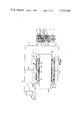
- FIGS. 4 and 5 One method of doing this is illustrated in FIGS. 4 and 5, wherein a series of six valves 150, 152, 154, 156, 158 and 160 is provided arranged on a manifold mounting and supply block 162.
- Each of the valves is constructed in similar fashion to the valve illustrated in FIG. 3, excepting that the inlet port for each valve comprises an axially directed passage 164, and of the two outlet ports from each valve, one outlet port 166 is radially directed, and the other outlet port 168 is axially directed.
- This is an illustration of the versatility of the valve construction, in that it is possible to arrange the inlet and outlet ports in a variety of configurations.
- Each of the inlet ports 164 terminates on the inside face of its valve, whereas each of the outlet ports 168 terminates on the outer face of each valve.
- Each of the outlet ports 166 is connected to a hydrostatic bearing, one of which is illustrated at 170, there being a sensor 172 in parallel with this hydrostatic bearing, and each of the outlet ports 168 communicates with a hydrostatic bearing, one of which is illustrated at 174, there being an exhaust pipe 176 in parallel with this bearing 174.
- valves are secured in two sets of three, to opposite faces of the manifold block 162, as is illustrated in FIG. 4, setscrews, one of which is illustrated at 178 being used for this purpose.
- a common supply passage 180 is formed axially through the manifold block 162, and is screwthreaded at 182, to receive a supply pipe (not shown) and blocked by a plug 184 at its opposite end.
- a transverse port 186, 188, 190 formed through the block 162, and communicating at the centre with the axial passage 180.
- each of the ports 186, 188, 190 communicates with an inlet port 164 of one of the valves, and in this manner there is a common supply from a single supply pipe, to each of the six valves 150, 152, 154, 156, 158 and 160.
- the block 162 can be mounted on a convenient part of the machine, where it is accessible for servicing the valves if required. This is of course a particularly neat arrangement.
- FIG. 6 An even more compact arrangement, which employs a stack of six valves is illustrated in FIG. 6, and in this arrangement, there is no manifold block.
- Securing bolts (not shown) are passed through the entire assembly, to clamp all the blocks together, thus nipping the diaphragm valve members in their operating positions.
- each of the intermediate valve blocks provides part of the construction of two valves of the type described with reference to FIG. 1.
- An inlet communication port 222 passes through the block from top to bottom, coaxially therewith, and it is a feature of this construction, that the communication port through each flexible valve member thus communicates with an inlet port in each of the two control faces with which that valve member co-operates.
- each of the outlet ports is connected via suitable conduits to a hydrostatic bearing as previously described with reference to FIG. 3.
- the upper end block 202 this is formed with an inlet port 228, which at its inner end communicates with an axially directed port 230, which forms an extension of the axial communicating inlet port 222 passing through all the intermediate blocks.
- the upper end block 202 also has a single outlet port 232, which is in communication with an annular recess 234 in the lower face of that block.
- the lower block 204 is identical with the upper block 202, and thus provides an inlet port 236, which communicates with the common inlet passage 222 passing through the intermediate blocks, a single annular recess 238 which provides one half of the bottom valve of the stack, and a single outlet port 240.
- each of the valves is thus provided between a pair of blocks, and each of the intermediate blocks forms part of two valves, whereas each of the end blocks forms part of a single valve.
- This construction also illustrates the fact that it is possible to have a common supply passage passing through the centres of a series of valves each generally constructed in the form shown in FIG. 3.
- the diaphragm 24,98,206,208,210,212,214,216 is shown as being of constant cross-sectional thickness. However, it may be desirable to use a diaphragm having a non-uniform cross-secton as a means of improving the responsive performance of the valve.
Landscapes
- Engineering & Computer Science (AREA)
- General Engineering & Computer Science (AREA)
- Mechanical Engineering (AREA)
- Magnetic Bearings And Hydrostatic Bearings (AREA)
- Fluid-Pressure Circuits (AREA)
Applications Claiming Priority (2)
| Application Number | Priority Date | Filing Date | Title |
|---|---|---|---|
| GB28208/77A GB1604050A (en) | 1977-07-06 | 1977-07-06 | Fluid-flow control valves |
| GB28208/77 | 1977-07-06 |
Publications (1)
| Publication Number | Publication Date |
|---|---|
| US4215903A true US4215903A (en) | 1980-08-05 |
Family
ID=10272031
Family Applications (1)
| Application Number | Title | Priority Date | Filing Date |
|---|---|---|---|
| US05/915,236 Expired - Lifetime US4215903A (en) | 1977-07-06 | 1978-06-13 | Fluid-flow control valves |
Country Status (8)
| Country | Link |
|---|---|
| US (1) | US4215903A (it) |
| JP (1) | JPS5417450A (it) |
| CA (1) | CA1086184A (it) |
| DE (1) | DE2829787A1 (it) |
| FR (1) | FR2414142A1 (it) |
| GB (1) | GB1604050A (it) |
| IT (1) | IT1103801B (it) |
| SE (1) | SE7806938L (it) |
Cited By (14)
| Publication number | Priority date | Publication date | Assignee | Title |
|---|---|---|---|---|
| US4322116A (en) * | 1979-08-02 | 1982-03-30 | Krupp Polysius Ag | Hydrodynamic bearing |
| US4381126A (en) * | 1980-07-07 | 1983-04-26 | Jeumont Schneider Corporation | Hydrostatic bearing with rotating sleeve |
| US4473786A (en) * | 1981-03-04 | 1984-09-25 | Hitachi, Ltd. | Method for controlling angular position and apparatus therefor |
| US4674952A (en) * | 1983-10-07 | 1987-06-23 | Sargent-Welch Scientific Company | Turbo molecular pump with improved bearing assembly |
| US4690572A (en) * | 1985-11-01 | 1987-09-01 | Nissan Motor Co., Ltd. | Static pressure gas bearing apparatus for turbocharger |
| US4696585A (en) * | 1986-01-17 | 1987-09-29 | Swearingen Judson S | Bearing support system with controllable spring rate |
| US4878820A (en) * | 1987-05-22 | 1989-11-07 | Hitachi, Ltd. | Screw compressor |
| US5022769A (en) * | 1988-03-17 | 1991-06-11 | U.S. Philips Corporation | Static bearing |
| US5042616A (en) * | 1988-07-29 | 1991-08-27 | General Electric Company | Self-regulating lubricant supply for thrust bearings |
| EP0798478A2 (en) * | 1996-03-27 | 1997-10-01 | Aesop Inc. | Hydrostatic bearing |
| US5769545A (en) * | 1996-12-04 | 1998-06-23 | Bently Nevada Corporation | Hydrostatic bearing for supporting rotating equipment, a fluid handling system associated therewith, a control system therefore, method and apparatus |
| US6142672A (en) * | 1998-06-22 | 2000-11-07 | Bently Nevada Corporation | Fluid flow and control system for a hydrostatic bearing supporting rotating equipment: method and apparatus |
| US20130263942A1 (en) * | 2010-10-25 | 2013-10-10 | Kawasaki Jukogyo Kabushiki Kaisha | Pressure reducing valve |
| US10077806B2 (en) * | 2015-07-15 | 2018-09-18 | National Tsing Hua University | Compact bearing system and machine stage system equipping the same |
Families Citing this family (6)
| Publication number | Priority date | Publication date | Assignee | Title |
|---|---|---|---|---|
| DE3144788A1 (de) * | 1981-11-11 | 1983-05-19 | Fa. Carl Zeiss, 7920 Heidenheim | Drossel fuer gaslager |
| GB8515858D0 (en) * | 1985-06-22 | 1985-07-24 | Jeavons Eng Ltd | Fluid flow governors and valves |
| DE3533037C1 (de) * | 1985-09-17 | 1986-12-18 | Robert 7321 Albershausen Schönfeld | In die Lagerflüssigkeits-Zuleitung zur Lagertasche einer hydrostatischen Lagerung oder Führung einschaltbarer Regler |
| GB2241992B (en) * | 1990-02-26 | 1994-04-20 | Nippon Seiko Kk | Static pressure gas bearing |
| US5064297A (en) * | 1990-02-26 | 1991-11-12 | Nippon Seiko Kabushiki Kaisha | Static pressure gas bearing with throttling control valve in housing |
| DE19737781A1 (de) * | 1997-08-29 | 1999-03-11 | Robert Schoenfeld | Regler zur Regelung eines mindestens einer Hydrostatik- oder Aerostatiktasche einer Lagerung, Gewindespindelmutter, oder einer Führung zugeführten Medienstromes |
Citations (4)
| Publication number | Priority date | Publication date | Assignee | Title |
|---|---|---|---|---|
| US2930391A (en) * | 1956-08-03 | 1960-03-29 | Alton S Bass | Vehicle brake line valve |
| US2992652A (en) * | 1956-11-01 | 1961-07-18 | Louis F Guenther | Safety valve |
| US3618383A (en) * | 1969-11-13 | 1971-11-09 | Grinnell Corp | Recirculating fluid supply system with flow measuring means |
| GB1337742A (en) * | 1970-07-10 | 1973-11-21 | Asquith Ltd William | Hydrostatic bearings arrangements for machine tools |
-
1977
- 1977-07-06 GB GB28208/77A patent/GB1604050A/en not_active Expired
-
1978
- 1978-06-13 US US05/915,236 patent/US4215903A/en not_active Expired - Lifetime
- 1978-06-16 SE SE7806938A patent/SE7806938L/xx unknown
- 1978-06-30 IT IT1268678A patent/IT1103801B/it active
- 1978-07-04 FR FR7820582A patent/FR2414142A1/fr active Granted
- 1978-07-05 CA CA306,856A patent/CA1086184A/en not_active Expired
- 1978-07-05 JP JP8185478A patent/JPS5417450A/ja active Pending
- 1978-07-06 DE DE19782829787 patent/DE2829787A1/de not_active Withdrawn
Patent Citations (4)
| Publication number | Priority date | Publication date | Assignee | Title |
|---|---|---|---|---|
| US2930391A (en) * | 1956-08-03 | 1960-03-29 | Alton S Bass | Vehicle brake line valve |
| US2992652A (en) * | 1956-11-01 | 1961-07-18 | Louis F Guenther | Safety valve |
| US3618383A (en) * | 1969-11-13 | 1971-11-09 | Grinnell Corp | Recirculating fluid supply system with flow measuring means |
| GB1337742A (en) * | 1970-07-10 | 1973-11-21 | Asquith Ltd William | Hydrostatic bearings arrangements for machine tools |
Cited By (16)
| Publication number | Priority date | Publication date | Assignee | Title |
|---|---|---|---|---|
| US4322116A (en) * | 1979-08-02 | 1982-03-30 | Krupp Polysius Ag | Hydrodynamic bearing |
| US4381126A (en) * | 1980-07-07 | 1983-04-26 | Jeumont Schneider Corporation | Hydrostatic bearing with rotating sleeve |
| US4473786A (en) * | 1981-03-04 | 1984-09-25 | Hitachi, Ltd. | Method for controlling angular position and apparatus therefor |
| US4674952A (en) * | 1983-10-07 | 1987-06-23 | Sargent-Welch Scientific Company | Turbo molecular pump with improved bearing assembly |
| US4690572A (en) * | 1985-11-01 | 1987-09-01 | Nissan Motor Co., Ltd. | Static pressure gas bearing apparatus for turbocharger |
| US4696585A (en) * | 1986-01-17 | 1987-09-29 | Swearingen Judson S | Bearing support system with controllable spring rate |
| US4878820A (en) * | 1987-05-22 | 1989-11-07 | Hitachi, Ltd. | Screw compressor |
| US5022769A (en) * | 1988-03-17 | 1991-06-11 | U.S. Philips Corporation | Static bearing |
| US5042616A (en) * | 1988-07-29 | 1991-08-27 | General Electric Company | Self-regulating lubricant supply for thrust bearings |
| EP0798478A2 (en) * | 1996-03-27 | 1997-10-01 | Aesop Inc. | Hydrostatic bearing |
| EP0798478A3 (en) * | 1996-03-27 | 1998-07-29 | Aesop Inc. | Hydrostatic bearing |
| US5769545A (en) * | 1996-12-04 | 1998-06-23 | Bently Nevada Corporation | Hydrostatic bearing for supporting rotating equipment, a fluid handling system associated therewith, a control system therefore, method and apparatus |
| US6142672A (en) * | 1998-06-22 | 2000-11-07 | Bently Nevada Corporation | Fluid flow and control system for a hydrostatic bearing supporting rotating equipment: method and apparatus |
| US20130263942A1 (en) * | 2010-10-25 | 2013-10-10 | Kawasaki Jukogyo Kabushiki Kaisha | Pressure reducing valve |
| US9141115B2 (en) * | 2010-10-25 | 2015-09-22 | Kawasaki Jukogyo Kabushiki Kaisha | Pressure reducing valve |
| US10077806B2 (en) * | 2015-07-15 | 2018-09-18 | National Tsing Hua University | Compact bearing system and machine stage system equipping the same |
Also Published As
| Publication number | Publication date |
|---|---|
| CA1086184A (en) | 1980-09-23 |
| FR2414142B3 (it) | 1981-03-06 |
| IT7812686A0 (it) | 1978-06-30 |
| IT1103801B (it) | 1985-10-14 |
| FR2414142A1 (fr) | 1979-08-03 |
| JPS5417450A (en) | 1979-02-08 |
| DE2829787A1 (de) | 1979-01-18 |
| GB1604050A (en) | 1981-12-02 |
| SE7806938L (sv) | 1979-01-07 |
Similar Documents
| Publication | Publication Date | Title |
|---|---|---|
| US4215903A (en) | Fluid-flow control valves | |
| US3993091A (en) | Manifold and valve system | |
| US4348942A (en) | Pressure-medium connection between a valve block and a load which has at least one double-acting pressure-medium motor | |
| US3411525A (en) | Fluid sampling valves | |
| US3411526A (en) | Hydraulic coupling | |
| GB1271268A (en) | Restricted bypass flow check valve | |
| US2459826A (en) | Fluid pressure bearing | |
| US2664267A (en) | Hydraulically balanced gate valve structure | |
| US3581772A (en) | Frictionless spool valve | |
| US2937656A (en) | Flow rate compensator | |
| US3437103A (en) | Flow control valve | |
| US4471805A (en) | Control valve | |
| US2969775A (en) | Valve | |
| US3042072A (en) | Diaphragm type valve structure | |
| US2912011A (en) | Valve structure | |
| US3238972A (en) | Pilot operated 3-way in-line valve | |
| US2774369A (en) | Valve | |
| JPH0437317B2 (it) | ||
| JPH0788911B2 (ja) | 一体流量制御装置付き弁ベース | |
| US3108611A (en) | Pressure regulator | |
| GB917423A (en) | Improvements in and relating to flow control valves | |
| US3590844A (en) | Device for dividing the flow of liquid into two parts | |
| US3588202A (en) | Automatic fluid control device | |
| US4889161A (en) | Compensated individual segment flow regulator | |
| US3516443A (en) | Pilot operated valve |