US4198664A - Nonrecorded section detection in a tape recorder apparatus - Google Patents
Nonrecorded section detection in a tape recorder apparatus Download PDFInfo
- Publication number
- US4198664A US4198664A US05/891,642 US89164278A US4198664A US 4198664 A US4198664 A US 4198664A US 89164278 A US89164278 A US 89164278A US 4198664 A US4198664 A US 4198664A
- Authority
- US
- United States
- Prior art keywords
- section detection
- detection system
- nonrecorded
- nonrecorded section
- output signal
- Prior art date
- Legal status (The legal status is an assumption and is not a legal conclusion. Google has not performed a legal analysis and makes no representation as to the accuracy of the status listed.)
- Expired - Lifetime
Links
- 238000001514 detection method Methods 0.000 title claims abstract description 71
- 230000004069 differentiation Effects 0.000 claims description 17
- 239000004065 semiconductor Substances 0.000 claims 6
- 230000000903 blocking effect Effects 0.000 claims 2
- 230000000087 stabilizing effect Effects 0.000 claims 1
- 230000007246 mechanism Effects 0.000 abstract description 9
- 239000003990 capacitor Substances 0.000 description 30
- 238000010586 diagram Methods 0.000 description 4
- 230000000994 depressogenic effect Effects 0.000 description 3
- 230000004048 modification Effects 0.000 description 2
- 238000012986 modification Methods 0.000 description 2
- 230000004913 activation Effects 0.000 description 1
- 230000002238 attenuated effect Effects 0.000 description 1
- 230000008878 coupling Effects 0.000 description 1
- 238000010168 coupling process Methods 0.000 description 1
- 238000005859 coupling reaction Methods 0.000 description 1
- 230000001681 protective effect Effects 0.000 description 1
Images

Classifications
-
- G—PHYSICS
- G11—INFORMATION STORAGE
- G11B—INFORMATION STORAGE BASED ON RELATIVE MOVEMENT BETWEEN RECORD CARRIER AND TRANSDUCER
- G11B15/00—Driving, starting or stopping record carriers of filamentary or web form; Driving both such record carriers and heads; Guiding such record carriers or containers therefor; Control thereof; Control of operating function
- G11B15/02—Control of operating function, e.g. switching from recording to reproducing
- G11B15/10—Manually-operated control; Solenoid-operated control
- G11B15/103—Manually-operated control; Solenoid-operated control electrically operated
-
- G—PHYSICS
- G11—INFORMATION STORAGE
- G11B—INFORMATION STORAGE BASED ON RELATIVE MOVEMENT BETWEEN RECORD CARRIER AND TRANSDUCER
- G11B27/00—Editing; Indexing; Addressing; Timing or synchronising; Monitoring; Measuring tape travel
- G11B27/10—Indexing; Addressing; Timing or synchronising; Measuring tape travel
- G11B27/19—Indexing; Addressing; Timing or synchronising; Measuring tape travel by using information detectable on the record carrier
- G11B27/22—Means responsive to presence or absence of recorded information signals
-
- G—PHYSICS
- G11—INFORMATION STORAGE
- G11B—INFORMATION STORAGE BASED ON RELATIVE MOVEMENT BETWEEN RECORD CARRIER AND TRANSDUCER
- G11B27/00—Editing; Indexing; Addressing; Timing or synchronising; Monitoring; Measuring tape travel
- G11B27/36—Monitoring, i.e. supervising the progress of recording or reproducing
Definitions
- the present invention relates to a nonrecorded section detecting system in a tape recorder apparatus.
- a charge/discharge circuit is connected to receive an output signal of an amplifier associated with a reproduction head for charging it when the reproduction head contacts a recorded portion.
- a tape feed mechanism is automatically shifted to its normal playback mode.
- an object of the present invention is to provide a nonrecorded section detection system for a tape recorder apparatus which ensures an accurate operation.
- Another object of the present invention is to provide a nonrecorded section detection system for a tape recorder apparatus which can accurately detect the nonrecorded section even when the power supply voltage varies.
- a switching transistor is connected to receive an output signal of an amplifier associated with a reproduction head when a nonrecorded section detection switch is depressed.
- a charge/discharge loop is connected to receive its charge current through the switching transistor when the reproduction head contacts a recorded section and, hence, the switching transistor is ON.
- FIG. 1 is a circuit diagram of a nonrecorded section detection system in a tape recorder apparatus of the prior art
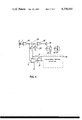
- FIG. 2 is a circuit diagram of an embodiment of a nonrecorded section detection system of the present invention
- FIG. 3 is a circuit diagram of another embodiment of a nonrecorded section detection system of the present invention.
- FIG. 4 is a schematic circuit diagram of a tape recorder apparatus employing a nonrecorded section detection system of the present invention.
- a nonrecorded section detection switch 3 is mechanically associated with a tape feed mechanism.
- the tape feed mechanism is shifted to a fast feed mode and the system is placed in a nonrecorded section detection mode, whereby a limiter/amplifier 2 is connected to receive the power supply through the nonrecorded section detection switch 3.
- the limiter/amplifier 2 develops an output signal to charge a charge/discharge circuit 7 through a capacitor 4 and a rectifying circuit 5.
- the limiter/amplifier 2 ceases to develop the charging signal and, therefore, the charge stored in a capacitor 8 is discharged through a resistor 9.
- a level detector 10 made of a Schmitt trigger circuit is actuated, thereby enabling a plunger to shift the tape feed mechanism into the normal playback mode.
- the time delay in the circuit 7, that is, a time interval beginning at the termination of the output signal from the limiter/amplifier 2 and ending at the switching of the level detector 10 is a most important factor to perform an accurate operation.
- This time interval greatly varies when a power supply voltage +B varies in the prior art system, because the charge/discharge circuit 7 receives the output signal of the limiter/amplifier 2 as its charging current and the output level of the limiter/amplifier 2 is considerably lower than the power supply level +B.
- FIG. 2 shows an embodiment of a nonrecorded section detection system of the present invention, which comprises a reproduction head 1, a limiter/amplifier 2, a nonrecorded section detection switch 3 associated with the tape feed mechanism, a capacitor 4, a resistor 31, and a switching transistor 6, the capacitor 4, the resistor 31 and the switching transistor 6 forming, in combination, a switching charge circuit.
- the present nonrecorded section detection system further comprises a charge/discharge circuit 7 including a capacitor 8 and a resistor 9, a level detector 10 comprising a Schmitt trigger circuit including transistors 11 and 12, a differentiation circuit 13 including a capacitor 14 and a resistor 15, a transistor 16, and a protective diode 17 for the transistor 16.
- the tape feed mechanism When the nonrecorded section detection switch 3 is depressed under the playback mode, the tape feed mechanism is shifted to a fast feed mode and the system is placed in the nonrecorded section detection mode.
- the reproduction signal from the reproduction head 1 is applied to the limiter/amplifier 2, which develops an output signal to the base electrode of the switching transistor 6 through a coupling circuit made of the capacitor 4 and the resistor 31.
- the output level of the limiter/amplifier 2 When the output level of the limiter/amplifier 2 is above the base to emitter voltage VBE of the switching transistor 6, the switching transistor 6 is ON and, hence, the capacitor 8 is charged up to the power supply voltage +B.
- charged voltage is applied to the level detector 10, whereby the transistor 11 is ON and the transistor 12 is OFF.
- the collector electrode A of the transistor 12 is maintained at the power supply level +B.
- the transistor 16 is OFF and, hence, a solenoid 18 is not enabled, because no voltage difference appears across the capacitor 14.
- the limiter/amplifier 2 ceases to develop its output signal and, therefore, the switching transistor 6 is OFF.
- the voltage charged across the capacitor 8 is discharged through the resistor 9.
- the transistor 11 is OFF and the transistor 12 is ON after a time period determined by the time constant of the charge/discharge circuit 7 and the threshold level of the level detector 10.
- the collector electrode A of the transistor 12 is maintained around the ground potential and, therefore, a charge current for the capacitor 14 flows from the power supply +B through the resistor 15, the capacitor 14 and the point A . This current renders the transistor 16 ON and, hence, the solenoid 18 is enabled.
- the solenoid 18 functions to shift the tape feed mechanism into its normal playback mode and to reset the nonrecorded section detection switch 3.
- the charge/discharge circuit 7 is connected to the power source voltage +B through the switching transistor 6 when the reproduction signal is derived from the limiter/amplifier 2. Therefore, the output level of the limiter/amplifier 2 is required not to be high but to be sufficient to turn on the switching transistor 6. Moreover, the variations of the power supply voltage +B is self-compensated. When the power supply voltage +B rises, both the voltage charge across the capacitor 8 and the threshold level of the level detector 10 are increased.
- the differentiation circuit 13 functions to prevent erroneous operation of the transistor 16. More particularly, the differentiation circuit 13 detects the trailing edge of the signal appearing at the point A , thereby conducting the transistor 16 only when the nonrecorded section is detected after the provision of the reproduction signal.
- FIG. 3 shows another embodiment of the nonrecorded section detection system of the present invention. Like elements corresponding to those of FIG. 2 are indicated by like numerals.
- An error operation preventing circuit 20 functions to prevent the above-mentioned error operation at the time of the power throw operation.
- a charging current flows to the capacitor 4 through the power supply source +B, the resistor 31, the capacitor 4 and the limiter/amplifier 2.
- a switching transistor 23 functions to disconnect the transistor 6.
- a charging current flows to the capacitor 14 from the power supply source +B, the resistor 15, the capacitor 14 and the level detector 10 when the power switch 19 is closed.
- a switching transistor 24 functions to disconnect the transistor 16.
- the base electrodes of the switching transistors 23 and 24 are connected to each other and to a delay circuit comprising a resistor 21 and a capacitor 22.
- a charging current flows to the capacitor 22 through the power supply source +B, the resistor 21 and the capacitor 22, whereby the voltage level appearing across the capacitor 22 is increased from zero toward the power supply voltage +B.
- the switching transistors 23 and 24 are maintained OFF until the voltage level appearing across the capacitor 22 becomes higher than the emitter level of the transistors 23 and 24 or the base to emitter voltage +VBE.
- the resistor 31, the capacitor 4, the transistor 6, the differentiation circuit 13 and the transistor 16 are disconnected.
- the aforementioned erroneous operation of the solenoid 18 at the power throw operation can be prevented by selecting the time period when the transistors 23 and 24 are OFF to be longer than the time required to charge the capacitors 4 and 14.
- FIG. 4 shows an example of a tape recorder apparatus employing the nonrecorded section detection system of the present invention.
- An output signal of an equalization amplifier 25 is applied to a low-frequency amplifier 29 via an electronic attenuator 26.
- the output signal of the low-frequency amplifier 29 activates a speaker 30.
- the output signal of the equalization amplifier 25 is also applied to the limiter/amplifier 2 associated with the nonrecorded section detection system.
- the output level of the reproduction head 1 is greater than that of the normal playback mode, because the tape feed speed is considerably high. Therefore, the monitor sound derived from the speaker 30 is very loud.
- the low-frequency amplifier 29 is cut off, thereby preventing the activation of the speaker 30 during the nonrecorded section detection operation.
- the electronic attenuator 26 includes a resistor 27 and an electronic variable resistor element 28 made of, for example, a transistor 28-a or a diode 28-b.
- the input level of the resistor element 28 is zero when the nonrecorded section detection switch 3 is open and, therefore, the output impedance of the element 28 is considerably high.
- the output signal of the equalization amplifier 25 is applied to the low-frequency amplifier 29 without attenuation.
- the input terminal of the element 28 is connected to the power supply source +B when the nonrecorded section detection switch 3 is closed and the system is placed in the nonrecorded section detection mode.
- the output impedance of the element 28 is reduced and, therefore, the output signal of the equalization amplifier 25 is applied to the low-frequency amplifier 29 after being attenuated by the resistor 27 and the output impedance of the element 28 and the small monitor sound is generated.
Landscapes
- Indexing, Searching, Synchronizing, And The Amount Of Synchronization Travel Of Record Carriers (AREA)
Applications Claiming Priority (2)
| Application Number | Priority Date | Filing Date | Title |
|---|---|---|---|
| JP50-1739 | 1975-08-28 | ||
| JP11901375 | 1975-08-28 |
Related Parent Applications (1)
| Application Number | Title | Priority Date | Filing Date |
|---|---|---|---|
| US05717925 Continuation | 1976-08-26 |
Publications (1)
| Publication Number | Publication Date |
|---|---|
| US4198664A true US4198664A (en) | 1980-04-15 |
Family
ID=14750818
Family Applications (1)
| Application Number | Title | Priority Date | Filing Date |
|---|---|---|---|
| US05/891,642 Expired - Lifetime US4198664A (en) | 1975-08-28 | 1978-03-30 | Nonrecorded section detection in a tape recorder apparatus |
Country Status (2)
| Country | Link |
|---|---|
| US (1) | US4198664A (enExample) |
| FR (1) | FR2322426A1 (enExample) |
Cited By (4)
| Publication number | Priority date | Publication date | Assignee | Title |
|---|---|---|---|---|
| US4365278A (en) * | 1979-08-31 | 1982-12-21 | Pioneer Electronic Corporation | Device for detecting non-recorded portions on magnetic tape |
| US4442464A (en) * | 1979-05-24 | 1984-04-10 | Tokyo Shibaura Denki Kabushiki Kaisha | Device for detecting a space between adjacent blocks of data recorded in a recording medium |
| FR2628877A1 (fr) * | 1988-03-18 | 1989-09-22 | Sgs Thomson Microelectronics | Dispositif de commutation d'une bobine |
| US5400188A (en) * | 1993-12-06 | 1995-03-21 | Ford Motor Company | Blank detector for cassette tape player |
Citations (4)
| Publication number | Priority date | Publication date | Assignee | Title |
|---|---|---|---|---|
| US3505485A (en) * | 1967-03-31 | 1970-04-07 | Rca Corp | Tape reeling search system with transistor search amplifier |
| US3984869A (en) * | 1974-03-28 | 1976-10-05 | Sharp Kabushiki Kaisha | Automatic program head positioning and tape feed control for tape decks |
| US4027336A (en) * | 1975-03-13 | 1977-05-31 | Rodney Bryant Jordan | Motor speed control device |
| US4118743A (en) * | 1976-05-31 | 1978-10-03 | Itsuki Ban | Cassette tape recorder with memory controlled selective by-pass |
-
1976
- 1976-08-27 FR FR7625959A patent/FR2322426A1/fr active Granted
-
1978
- 1978-03-30 US US05/891,642 patent/US4198664A/en not_active Expired - Lifetime
Patent Citations (4)
| Publication number | Priority date | Publication date | Assignee | Title |
|---|---|---|---|---|
| US3505485A (en) * | 1967-03-31 | 1970-04-07 | Rca Corp | Tape reeling search system with transistor search amplifier |
| US3984869A (en) * | 1974-03-28 | 1976-10-05 | Sharp Kabushiki Kaisha | Automatic program head positioning and tape feed control for tape decks |
| US4027336A (en) * | 1975-03-13 | 1977-05-31 | Rodney Bryant Jordan | Motor speed control device |
| US4118743A (en) * | 1976-05-31 | 1978-10-03 | Itsuki Ban | Cassette tape recorder with memory controlled selective by-pass |
Cited By (7)
| Publication number | Priority date | Publication date | Assignee | Title |
|---|---|---|---|---|
| US4442464A (en) * | 1979-05-24 | 1984-04-10 | Tokyo Shibaura Denki Kabushiki Kaisha | Device for detecting a space between adjacent blocks of data recorded in a recording medium |
| US4680652A (en) * | 1979-05-24 | 1987-07-14 | Tokyo Shibaura Denki Kabushiki | Device for detecting a space between adjacent blocks of data recorded in a recording medium |
| US4365278A (en) * | 1979-08-31 | 1982-12-21 | Pioneer Electronic Corporation | Device for detecting non-recorded portions on magnetic tape |
| FR2628877A1 (fr) * | 1988-03-18 | 1989-09-22 | Sgs Thomson Microelectronics | Dispositif de commutation d'une bobine |
| EP0334775A1 (fr) * | 1988-03-18 | 1989-09-27 | STMicroelectronics S.A. | Dispositif de commutation d'une bobine |
| US5016122A (en) * | 1988-03-18 | 1991-05-14 | Sgs-Thomson Microelectronics S.A. | Coil switching device |
| US5400188A (en) * | 1993-12-06 | 1995-03-21 | Ford Motor Company | Blank detector for cassette tape player |
Also Published As
| Publication number | Publication date |
|---|---|
| FR2322426B1 (enExample) | 1980-06-06 |
| FR2322426A1 (fr) | 1977-03-25 |
| AU1717776A (en) | 1978-03-02 |
Similar Documents
| Publication | Publication Date | Title |
|---|---|---|
| GB1351993A (en) | Disc file agc circuit | |
| US3984869A (en) | Automatic program head positioning and tape feed control for tape decks | |
| US3505485A (en) | Tape reeling search system with transistor search amplifier | |
| US4198664A (en) | Nonrecorded section detection in a tape recorder apparatus | |
| US3206689A (en) | Pulse signal agc circuitry | |
| US4580179A (en) | Playback search control device for a tape recorder | |
| US3758726A (en) | Electric condition control device for a transcribing machine | |
| US4220979A (en) | Bias level setting circuit for tape recorders with staircase high frequency signal | |
| US4115821A (en) | Nonrecorded section detection in a tape recorder apparatus | |
| US4636878A (en) | Combined detector circuit for detecting a tape end or unrecorded area of a tape | |
| US3632893A (en) | Control device for a transcribing machine with automatic recall | |
| GB1565222A (en) | Detection of nonrecoreded section of a magnetic tape non-recorded section of magnetic tape | |
| US4365278A (en) | Device for detecting non-recorded portions on magnetic tape | |
| US3050692A (en) | Automatic gain control | |
| US5016122A (en) | Coil switching device | |
| JPS57181450A (en) | Detector for intermusic of tape recorder | |
| JPS55101114A (en) | Magnetic recording and reproducing device | |
| US4597022A (en) | Mode switching circuit for use in a reproducing apparatus | |
| JPS55139613A (en) | Tape recorder | |
| EP0436939A2 (en) | Optical disk data reproducing apparatus | |
| US3489862A (en) | Apparatus for automatic detection and alarm of fouled magnetic head | |
| JPS5827381Y2 (ja) | テ−プレコ−ダ−の曲間検出装置 | |
| KR870002314Y1 (ko) | 전자식 구동 카세트 데크에서의 무신호 녹음부분 형성회로 | |
| US3476953A (en) | Automatic switching control circuit | |
| JPH0416287Y2 (enExample) |