US4178654A - Floor polishing machines - Google Patents
Floor polishing machines Download PDFInfo
- Publication number
- US4178654A US4178654A US05/845,677 US84567777A US4178654A US 4178654 A US4178654 A US 4178654A US 84567777 A US84567777 A US 84567777A US 4178654 A US4178654 A US 4178654A
- Authority
- US
- United States
- Prior art keywords
- housing
- floor
- polishing
- fan
- channel
- Prior art date
- Legal status (The legal status is an assumption and is not a legal conclusion. Google has not performed a legal analysis and makes no representation as to the accuracy of the status listed.)
- Expired - Lifetime
Links
Images


Classifications
-
- A—HUMAN NECESSITIES
- A47—FURNITURE; DOMESTIC ARTICLES OR APPLIANCES; COFFEE MILLS; SPICE MILLS; SUCTION CLEANERS IN GENERAL
- A47L—DOMESTIC WASHING OR CLEANING; SUCTION CLEANERS IN GENERAL
- A47L11/00—Machines for cleaning floors, carpets, furniture, walls, or wall coverings
- A47L11/40—Parts or details of machines not provided for in groups A47L11/02 - A47L11/38, or not restricted to one of these groups, e.g. handles, arrangements of switches, skirts, buffers, levers
- A47L11/4063—Driving means; Transmission means therefor
- A47L11/4069—Driving or transmission means for the cleaning tools
-
- A—HUMAN NECESSITIES
- A47—FURNITURE; DOMESTIC ARTICLES OR APPLIANCES; COFFEE MILLS; SPICE MILLS; SUCTION CLEANERS IN GENERAL
- A47L—DOMESTIC WASHING OR CLEANING; SUCTION CLEANERS IN GENERAL
- A47L11/00—Machines for cleaning floors, carpets, furniture, walls, or wall coverings
- A47L11/02—Floor surfacing or polishing machines
- A47L11/20—Floor surfacing or polishing machines combined with vacuum cleaning devices
- A47L11/204—Floor surfacing or polishing machines combined with vacuum cleaning devices having combined drive for brushes and for vacuum cleaning
- A47L11/206—Floor surfacing or polishing machines combined with vacuum cleaning devices having combined drive for brushes and for vacuum cleaning for rotary disc brushes
- A47L11/2065—Floor surfacing or polishing machines combined with vacuum cleaning devices having combined drive for brushes and for vacuum cleaning for rotary disc brushes having only one disc brush
Definitions
- the present invention relates to a floor polishing machine.
- a floor polishing machine comprising a rotary brush, drive means for the brush, and means for producing, in use, an updraught around the periphery of the brush.
- the means for producing the updraught is in the form of a fan arranged to rotate when the brush is rotating.
- the fan may be driven directly from the drive to the brush or it may be driven through gears or belts from the drive means to the brush or by any other suitable means.
- particulate matter such as dust lying on the area of floor or other surface being polished, can be removed therefrom.
- the floor polisher of the present invention may be operated without a vacuum motor and in this case the floor polisher is very quiet in operation which makes it extremely suitable for use in hospitals and other environments where noise is disruptive.
- the present invention also provides a skirt member for use with a floor polishing machine comprising an annular conduit arranged to be in communication with a vacuum motor and containing a plurality of apertures for collecting particulate matter from a floor.
- FIG. 1 is a side elevation partially in section of a floor polisher in accordance with the present invention
- FIG. 2 is a plan view of the floor polisher of FIG. 1;
- FIG. 3 is an underneath view of the floor polisher of FIG. 1 with parts deleted for clarity;
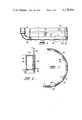
- FIG. 4 is a side elevation partially broken away of a novel skirt which may be used in conjunction with the floor polisher of the present invention
- FIG. 5 is an underneath view of the skirt of FIG. 4.
- FIG. 6 is a section taken along the line 6--6 of FIGS. 4 and 5.
- FIGS. 1 to 3 of the drawings there is shown a floor polisher 10 comprising a rotary brush 12 with a backing member 13 having a plurality of ground engaging bristles bonded thereto.
- the brush 12 is connected through a drive train to an electric motor 14.
- the motor 14 is arranged to drive the brush 12.
- the brush 12 is located within a housing 16 having a depending ground engaging skirt 18.
- the drive train for the brush 12 comprises a shaft 20 extending from the motor 14 and connected at its lower end as seen in FIG. 1, to a pulley wheel 22.
- the pulley wheel 22 is connected to a larger diameter pulley wheel 24 by means of a driving belt 26 (see FIG. 3 in which the brush 12 has been omitted for greater clarity) to provide a first reduction in the drive from the motor 14.
- the pulley wheel 24 is mounted on a plate 28.
- a shaft 30 extends rotatably through the plate 28 and drivingly connects the pulley wheel 24 to a further pulley wheel 32 of a diameter similar to that of the pulley wheel 22.
- the pulley wheel 32 is connected by means of a driving belt 34 to a larger diameter pulley wheel 36 having a diameter similar to that of the pulley wheel 24, to provide a second reduction in the drive from the motor 14.
- the pulley wheel 36 is rotatably mounted on a plate 38 by means of a shaft 40.
- the pulley wheel 36 is firmly and rigidly connected to the upper surface of the brush 12 by means of bolts extending through a plate 42, which is welded to the pulley wheel 36, into the backing member 13 of the brush 12.
- a fan member 44 is rigidly mounted on the drive shaft 20 from the motor 14 just about the pulley wheel 20.
- the fan member 44 is circular in shape and has a plurality of turned-down (as seen in FIG. 1) blade members 46 formed around its entire periphery.
- the housing 16 has an upstanding channel 48 extending around a major proportion of its periphery.
- the channel 48 is of gradually increasing height up to its termination at a vertical conduit 50.
- the conduit 50 communicates through an opening 53 with a container 52 arranged to receive and collect dust and other particulate matter such as by means of for example, a hessian bag.
- the container 52 is located within a vertical cylindrical housing 54 having a horizontal row of air outlet holes 56 adjacent its low end.
- the housing 54 is mounted in part on a portion of the upper surface of the housing 16 not having the channel 48 and in part on a plate 58.
- the parts of the floor polishing machine described above operate as follows.
- the electric motor 14 is energised so causing the shaft 20 to rotate at the same speed as the motor 14.
- the rotation of the shaft 20 causes the fan 44 to rotate at the same speed and the brush 12 to rotate at a reduced speed as determined by the arrangement of pulleys and belts described above.
- the rotation of the brush 12 causes the bristles thereof to rub against the floor or other surface with which they are in engagement and so to polish the same, usually with the aid of a polishing medium which has been previously applied.
- the simultaneous rotation of the fan 44 causes an updraught to be created around the periphery of the brush 12.
- the fan 44 is so arranged that at operating speed the updraught is sufficient to lift particulate matter such as dust from the floor or other surface for removal through the conduit 50.
- the channel 48 is provided to enhance the action of the fan 44 and has a cyclone effect in the movement of the particulate matter into and up the conduit 50.
- the particulate matter is fed from the conduit 50 into the container 52 where it is collected for subsequent disposal.
- the air flow passes through the collection medium such as the hessian bag, to exit through the holes 56.
- An aperture 60 is provided in the skirt 18. This aperture is in communication with a vertical conduit 62 which leads into the container 52 through the opening 53 as does the conduit 50.
- the container 52 is located within the upper part of the vertical cylindrical housing 54.
- the lower part of the cylindrical housing 54 is separated from the upper part by a perforated plate 66, and contains an extraction fan 68 driven by a motor 70.
- the extraction fan 68 is actuated by the motor 70 so as to produce an updraught in the conduit 62. This in turn causes a horizontal suction effect through the aperture 60 and removes particulate matter from a portion of the surface adjacent the aperture 60.
- the floor polishing machine 10 is further provided with a conventional driving handle 72 and a pair of conventional ground engaging wheels 74 retractably mounted on a mounting plate 76 by means of pivotally mounted arms 78.
- the fan 44 is typically driven at a speed in the range from 600-4500 rpm to generate sufficient updraught for satisfactory removal of particulate matter.
- FIGS. 4 to 6 of the accompanying drawings there is shown a novel skirt 80 which may be used to replace the skirt 18 of the embodiment of the invention illustrated in FIGS. 1 to 3.
- the skirt 80 depends from a housing 16 as shown in FIG. 1.
- the skirt 80 comprises an annular conduit 82 comprising an outer vertical wall 84, and inner vertical wall 86 and horizontal upper and lower walls 88 and 90 respectively.
- a cylindrical member 92 is attached to the underside of the housing 16. Further, the outer vertical wall 84 of the annular conduit 82 contains an upward facing slot which receives the lower portion of the cylindrical member 92. The cylindrical member 92 is bonded to the annular conduit 82 by any convenient means such as by adhesive. The outer vertical wall also contains a downward facing slot which receives the upper portion of a ground engaging member 94. The ground engaging member 94 is also bonded to the annular conduit 82 by any convenient means such as by adhesive.
- the annular conduit 82 is connected at one point to a vacuum motor such as motor 70 shown in FIG. 1 through an opening 96 in the outer vertical wall 84 and a vertical conduit 98.
- the lower horizontal wall 90 of the annular conduit 82 contains a plurality of spaced apertures 100. Further, the ground engaging member contains cut away portions 102 at locations corresponding to the apertures 100.
- the annular member 82 is preferably formed of a flexible material such as rubber or non-rigid plastics material to enable the skirt 80 to conform closely to the contours of the floor when in use.
- the ground engaging member 94 is preferably formed of a relatively hard material such as polypropylene or polyethylene to prevent undue wear in use.
- the skirt 80 in conjunction with the vacuum motor but independently of the fan member 44, causes particulate matter lying on the floor to be sucked through the apertures 100 into the annular conduit 82 and thence through the opening 96 into the vertical conduit 98 for collection in conventional manner. This enhances the operation of the apparatus of FIGS. 1 to 3 in that the floor is cleaned even more efficiently whilst being polished.
- the fan 44 could be provided with wider blades 46 if desired. Further the fan 44 could be driven by gears or belts rather than a direct drive as shown. Still further, for increased updraught a two stage fan or a multiple stage fan or fans could be used.
- the annular conduit 82 can have any suitable cross-section. For example, it may be square or circular as well as rectangular as shown in the drawings.
Landscapes
- Grinding Of Cylindrical And Plane Surfaces (AREA)
Applications Claiming Priority (2)
| Application Number | Priority Date | Filing Date | Title |
|---|---|---|---|
| AUPC8282 | 1976-11-29 | ||
| AUPC828276 | 1976-11-29 |
Publications (2)
| Publication Number | Publication Date |
|---|---|
| US4178654A true US4178654A (en) | 1979-12-18 |
| US4178654B1 US4178654B1 (OSRAM) | 1992-02-04 |
Family
ID=3766860
Family Applications (1)
| Application Number | Title | Priority Date | Filing Date |
|---|---|---|---|
| US05/845,677 Expired - Lifetime US4178654A (en) | 1976-11-29 | 1977-10-26 | Floor polishing machines |
Country Status (3)
| Country | Link |
|---|---|
| US (1) | US4178654A (OSRAM) |
| GB (1) | GB1553142A (OSRAM) |
| PH (1) | PH14998A (OSRAM) |
Cited By (15)
| Publication number | Priority date | Publication date | Assignee | Title |
|---|---|---|---|---|
| US4598440A (en) * | 1984-07-19 | 1986-07-08 | Pioneer/Eclipse Corporation | High speed floor buffing machine and floor buffing method |
| US4701970A (en) * | 1984-07-19 | 1987-10-27 | Pioneer/Eclipse Corp. | High speed floor buffing machine and floor buffing pad |
| US4701976A (en) * | 1985-10-15 | 1987-10-27 | Hako Minuteman, Inc. | High speed floor burnisher |
| US4715087A (en) * | 1985-12-11 | 1987-12-29 | Hako Minuteman, Inc. | High speed floor burnisher |
| US4720886A (en) * | 1986-10-17 | 1988-01-26 | Hako Minuteman, Inc. | Floor polishing machine |
| US4731956A (en) * | 1986-10-21 | 1988-03-22 | Advance Machine Company | Floor polishing machine |
| US4739534A (en) * | 1984-07-19 | 1988-04-26 | Pioneer/Eclipse Corp. | High speed floor buffing pad and holder |
| US4805258A (en) * | 1987-09-22 | 1989-02-21 | Tennant Trend Inc. | Battery powered walk behind floor burnisher |
| US5088151A (en) * | 1991-04-25 | 1992-02-18 | Advance Machine Company | Collection system for a floor polishing machine |
| DE4141703A1 (de) * | 1991-12-18 | 1993-06-24 | Hako Gmbh & Co | Poliermaschine |
| US5974626A (en) * | 1997-03-26 | 1999-11-02 | Nilfisk-Advance, Inc. | Collection system for a floor polishing machine |
| WO2001017414A1 (en) * | 1999-09-09 | 2001-03-15 | Oreck Holdings, Llc | Dust shield apparatus for floor machines |
| US20030070252A1 (en) * | 2001-10-12 | 2003-04-17 | Roger Pedlar | Scrubbing machine passive recycling |
| US20040221417A1 (en) * | 2003-05-05 | 2004-11-11 | Alto U.S. Inc. | Floor cleaning machine with dust control apparatus and associate method of use |
| US20110030163A1 (en) * | 2009-08-05 | 2011-02-10 | Karcher N. America, Inc. | Method and apparatus for extended use of cleaning fluid in a floor cleaning machine |
Families Citing this family (1)
| Publication number | Priority date | Publication date | Assignee | Title |
|---|---|---|---|---|
| EP1603443A4 (en) * | 2003-02-21 | 2006-12-13 | Joseph Deleo | POLISHING VACUUM CLEANER FOR HARD SURFACES |
Citations (8)
| Publication number | Priority date | Publication date | Assignee | Title |
|---|---|---|---|---|
| US928456A (en) * | 1908-07-09 | 1909-07-20 | Henry Harry Johnson | Sweeping-machine. |
| US935558A (en) * | 1908-11-16 | 1909-09-28 | Electric Suction Sweeper Company | Carpet sweeper and cleaner. |
| US2250177A (en) * | 1938-11-02 | 1941-07-22 | Boccasile Nicholas | Floor washing machine |
| US2415372A (en) * | 1945-06-16 | 1947-02-04 | B F Sturtevant Co | Sweeper |
| US2663893A (en) * | 1950-07-14 | 1953-12-29 | La Vern A Percy | Floor treatment implement with vacuum cleaning mechanism |
| US3314099A (en) * | 1965-06-07 | 1967-04-18 | Ed A Otto | Floor cleaning apparatus |
| US3375540A (en) * | 1965-07-19 | 1968-04-02 | Elmer A. Hyde | Attachment for floor cleaning machine |
| US3719966A (en) * | 1970-12-09 | 1973-03-13 | Contract Cleaning Co Pty Ltd | Combined floor-polisher and suction cleaner |
-
1977
- 1977-10-14 GB GB42802/77A patent/GB1553142A/en not_active Expired
- 1977-10-26 US US05/845,677 patent/US4178654A/en not_active Expired - Lifetime
- 1977-11-02 PH PH20392A patent/PH14998A/en unknown
Patent Citations (8)
| Publication number | Priority date | Publication date | Assignee | Title |
|---|---|---|---|---|
| US928456A (en) * | 1908-07-09 | 1909-07-20 | Henry Harry Johnson | Sweeping-machine. |
| US935558A (en) * | 1908-11-16 | 1909-09-28 | Electric Suction Sweeper Company | Carpet sweeper and cleaner. |
| US2250177A (en) * | 1938-11-02 | 1941-07-22 | Boccasile Nicholas | Floor washing machine |
| US2415372A (en) * | 1945-06-16 | 1947-02-04 | B F Sturtevant Co | Sweeper |
| US2663893A (en) * | 1950-07-14 | 1953-12-29 | La Vern A Percy | Floor treatment implement with vacuum cleaning mechanism |
| US3314099A (en) * | 1965-06-07 | 1967-04-18 | Ed A Otto | Floor cleaning apparatus |
| US3375540A (en) * | 1965-07-19 | 1968-04-02 | Elmer A. Hyde | Attachment for floor cleaning machine |
| US3719966A (en) * | 1970-12-09 | 1973-03-13 | Contract Cleaning Co Pty Ltd | Combined floor-polisher and suction cleaner |
Cited By (20)
| Publication number | Priority date | Publication date | Assignee | Title |
|---|---|---|---|---|
| US4598440A (en) * | 1984-07-19 | 1986-07-08 | Pioneer/Eclipse Corporation | High speed floor buffing machine and floor buffing method |
| US4701970A (en) * | 1984-07-19 | 1987-10-27 | Pioneer/Eclipse Corp. | High speed floor buffing machine and floor buffing pad |
| US4739534A (en) * | 1984-07-19 | 1988-04-26 | Pioneer/Eclipse Corp. | High speed floor buffing pad and holder |
| US4701976A (en) * | 1985-10-15 | 1987-10-27 | Hako Minuteman, Inc. | High speed floor burnisher |
| US4715087A (en) * | 1985-12-11 | 1987-12-29 | Hako Minuteman, Inc. | High speed floor burnisher |
| US4720886A (en) * | 1986-10-17 | 1988-01-26 | Hako Minuteman, Inc. | Floor polishing machine |
| AU593377B2 (en) * | 1986-10-17 | 1990-02-08 | Hako Minuteman, Inc. | Improvements in floor polishing machine |
| US4731956A (en) * | 1986-10-21 | 1988-03-22 | Advance Machine Company | Floor polishing machine |
| US4805258A (en) * | 1987-09-22 | 1989-02-21 | Tennant Trend Inc. | Battery powered walk behind floor burnisher |
| US5088151A (en) * | 1991-04-25 | 1992-02-18 | Advance Machine Company | Collection system for a floor polishing machine |
| DE4141703A1 (de) * | 1991-12-18 | 1993-06-24 | Hako Gmbh & Co | Poliermaschine |
| US5974626A (en) * | 1997-03-26 | 1999-11-02 | Nilfisk-Advance, Inc. | Collection system for a floor polishing machine |
| WO2001017414A1 (en) * | 1999-09-09 | 2001-03-15 | Oreck Holdings, Llc | Dust shield apparatus for floor machines |
| US6240596B1 (en) * | 1999-09-09 | 2001-06-05 | Oreck Holdings, Llc | Dust shield apparatus for floor machines |
| US20030070252A1 (en) * | 2001-10-12 | 2003-04-17 | Roger Pedlar | Scrubbing machine passive recycling |
| US7025835B2 (en) * | 2001-10-12 | 2006-04-11 | Castle Rock Industries | Scrubbing machine passive recycling |
| US20040221417A1 (en) * | 2003-05-05 | 2004-11-11 | Alto U.S. Inc. | Floor cleaning machine with dust control apparatus and associate method of use |
| US7162771B2 (en) | 2003-05-05 | 2007-01-16 | Alto U.S. Inc. | Floor cleaning machine with dust control apparatus and associate method of use |
| US20110030163A1 (en) * | 2009-08-05 | 2011-02-10 | Karcher N. America, Inc. | Method and apparatus for extended use of cleaning fluid in a floor cleaning machine |
| US8966693B2 (en) * | 2009-08-05 | 2015-03-03 | Karcher N. America, Inc. | Method and apparatus for extended use of cleaning fluid in a floor cleaning machine |
Also Published As
| Publication number | Publication date |
|---|---|
| PH14998A (en) | 1982-03-22 |
| GB1553142A (en) | 1979-09-19 |
| US4178654B1 (OSRAM) | 1992-02-04 |
Similar Documents
| Publication | Publication Date | Title |
|---|---|---|
| US4178654A (en) | Floor polishing machines | |
| US4967516A (en) | Debris collection system for a surface treating tool | |
| EP0649705B1 (en) | Dry barrel finishing machine | |
| US4731956A (en) | Floor polishing machine | |
| US6948412B2 (en) | Motor driven wood working tool with vacuum feature | |
| US4598440A (en) | High speed floor buffing machine and floor buffing method | |
| US3906585A (en) | Floor treating apparatus | |
| KR100778790B1 (ko) | 진공식 표면연마 머신 | |
| US4577364A (en) | Floor cleaning machine | |
| US7553217B2 (en) | Dust-collecting container for a hand electric machine tool | |
| US5027470A (en) | Dustless surface treatment machine | |
| US20070044609A1 (en) | Motor driven wood working tool with vacuum feature | |
| US5088151A (en) | Collection system for a floor polishing machine | |
| US3495358A (en) | Surface treatment apparatus | |
| US3797065A (en) | Integrated foam extracting and rotary scrubbing machine | |
| AU570075B2 (en) | Suction housing for vacuum sanding devices | |
| GB2428612A (en) | Grinding machine with a dust collection device | |
| US4720886A (en) | Floor polishing machine | |
| US2672635A (en) | Boot polishing machine | |
| US3186022A (en) | Surface treating apparatus | |
| EP0293149A2 (en) | Floor cleaning apparatus | |
| CN201776674U (zh) | 磨砂机 | |
| WO1990012532A1 (en) | Filter cleaner/separator for dry and wet suction machines | |
| EP0931501A2 (en) | Attachment for a floor maintenance machine | |
| CN102233532A (zh) | 磨砂机 |
Legal Events
| Date | Code | Title | Description |
|---|---|---|---|
| RR | Request for reexamination filed |
Effective date: 19901004 |
|
| B1 | Reexamination certificate first reexamination | ||
| AS | Assignment |
Owner name: MINUTEMAN INTERNATIONAL, INC., ILLINOIS Free format text: ASSIGNMENT OF ASSIGNORS INTEREST;ASSIGNOR:HAKO MINUTEMAN, INC.;REEL/FRAME:007378/0664 Effective date: 19940415 |