US4176951A - Rotating birefringent ellipsometer and its application to photoelasticimetry - Google Patents
Rotating birefringent ellipsometer and its application to photoelasticimetry Download PDFInfo
- Publication number
- US4176951A US4176951A US05/835,004 US83500477A US4176951A US 4176951 A US4176951 A US 4176951A US 83500477 A US83500477 A US 83500477A US 4176951 A US4176951 A US 4176951A
- Authority
- US
- United States
- Prior art keywords
- quarter
- polarizer
- photodetector
- wave plate
- reference signal
- Prior art date
- Legal status (The legal status is an assumption and is not a legal conclusion. Google has not performed a legal analysis and makes no representation as to the accuracy of the status listed.)
- Expired - Lifetime
Links
Images


Classifications
-
- G—PHYSICS
- G01—MEASURING; TESTING
- G01N—INVESTIGATING OR ANALYSING MATERIALS BY DETERMINING THEIR CHEMICAL OR PHYSICAL PROPERTIES
- G01N21/00—Investigating or analysing materials by the use of optical means, i.e. using sub-millimetre waves, infrared, visible or ultraviolet light
- G01N21/17—Systems in which incident light is modified in accordance with the properties of the material investigated
- G01N21/21—Polarisation-affecting properties
- G01N21/211—Ellipsometry
Definitions
- This invention relates to a rotating birefringent-plate ellipsometer and its application to photoelasticimetry.
- the present invention relates to a process and apparatus for analyzing the polarization components of incident light as well as processes and apparatus for determining the characteristics of birefringent media onto which a light beam of known polarization is directed.
- a polarized light wave is, in general, polarized elliptically and, in the limit, it is linearly or circularly polarized.
- the polarization parameters are ⁇ and ⁇ .
- ⁇ defines the orientation of the major axis of the ellipse with respect to a reference direction
- ⁇ defines the flatness of the ellipse. That is, ⁇ is equal in absolute value to the ratio of the minor axis of the ellipse to the major axis of the ellipse.
- a birefringent plate is defined by the orientation ⁇ of its fast axis and by the phase shift ⁇ produced by the plate between the light vectors moving along the fast axis and along the slow axis of the plate respectively.
- the parameter ⁇ is equal to ⁇ /4. If a circularly polarized light beam passes through a birefringent plate of parameters ⁇ and ⁇ , one will have at the output of the plate:
- Linear light is characterized by the fact that the parameter ⁇ is equal to zero.
- linear light falling on a birefringent plate of parameters ⁇ and ⁇ along the bisectors of the axes of this birefringent will, after having passed through the birefringent, become a light wave characterized by the following parameters ⁇ and ⁇ :
- a retractable quarter-wave plate can be added to the unit.
- the method of use then consists of retracting the quarter-wave plate and measuring ⁇ as in the previous case, and then inserting the quarter-wave plate with an orientation corresponding to that of the angle ⁇ measured.
- the phase of the component having twice the frequency of the frequency of rotation of the rotating analyzer supplies the parameter ⁇ - ⁇ .
- this second method which permits a measurement of ⁇ without passing through a sinusoidal function of this parameter, is relatively complicated.
- An object of the present invention is to provide a new ellipsometer which permits direct measurement of the parameters ⁇ and ⁇ without passing through a trigonometric function of these parameters, this apparatus being particularly simple.
- Another object of the present invention is to contemplate applications of such an ellipsometer to photoelastimetric measurements by reflection or transmission.
- Still another object is to provide a photoelasticimeter having two wavelengths to permit measurements of the characteristic parameters of a polarized wave or of a birefringent model to be studied while avoiding the indeterminateness within ⁇ radians which is present in the case of measurements carried out with a single wavelength.
- the present invention provides an ellipsometer for the measurement of the polarization parameters ⁇ and ⁇ of a light wave comprising a birefringent rotating at a constant angular velocity ⁇ ; an orientable quarter-wave plate; a polarizer; a photoelectric receiver; means for supplying reference signals of the frequencies 2 ⁇ and 4 ⁇ ; electronic means for synchronous detection of the output signals of the receiver having the frequencies 2 ⁇ and 4 ⁇ in relation to the reference signals, the signal of frequency 2 ⁇ being cancelled by the quarter-wave plate, the orientation of which then provides an indication of the first parameter; and means for measuring the phase of the signal of frequency 4 ⁇ thereby supplying an indication of the second parameter.
- the present invention also provides special arrangements of the components included in the above ellipsometer to permit analysis of the parameters of a model to be studied, the apparatus receiving a light wave of predetermined polarization. It will be noted that one advantage of the present invention is that only phase measurements and no amplitude measurements are effected. One therefore is not hampered by fluctuations in amplitude of the incident light beam and accordingly it is not necessary to provide amplitude control of this beam nor to take precautionary measures with respect to parasitic light.
- the letter “ ⁇ ” is used to designate both frequencies and angular frequencies (pulsations) and the expression "birefringent” as a noun is used to designate an element which exhibits birefringence; for instance, a “rotating birefringent” may designate a mechanically rotating birefringent plate or a Kerr cell subjected to a rotating field.
- FIG. 1 shows diagrammatically, in block form, an automatic ellipsometer arrangement of the prior art
- FIGS. 2a, 2b and 2c are block diagrams explaining the operation of the present invention.
- FIG. 3 shows diagrammatically, in block form, an automatic ellipsometer in accordance with the present invention
- FIG. 4 shows diagrammatically, in block form, a reflection photoelasticimeter in accordance with the present invention
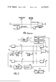
- FIG. 5 shows diagrammatically, in block form, an automatic multiple-wavelength photoelasticimeter in accordance with the present invention.
- FIG. 6 illustrates an annular polarizer
- This apparatus is also provided, in order to supply reference signals, with an auxiliary source of light 6 having a beam which also passes through the rotating analyzer 3 and then through a stationary polarizer 9 before reaching a photodetector 7 which supplies an output signal to a terminal 8.
- a method which makes it possible partially to overcome these drawbacks consists in inserting in the arrangement, as shown in the figure, the retractable and orientable quarter-wave plate 2 after the previous measurement has supplied the value of the parameter ⁇ .
- the quarter-wave plate is inserted with an orientation ⁇ corresponding to this value ⁇ . There is thus obtained at the terminal 5 a signal whose component of frequency 2 ⁇ t is
- a beam 10 which is to be analyzed passes, in succession, through an orientable quarter-wave plate 11, a birefringent plate (or birefringent) 12 rotating at a constant angular frequency ⁇ (for instance, by a motor 13) and a polarizer 14. It then strikes a photodetector 15 which supplies electric output signals at a terminal 16.
- the rotating birefringent is characterized by its phase shift ⁇ .
- a reference signal having a frequency of 2 ⁇ t is generated by a device comprising a source by light 20 having an output beam which passes sequentially through a circular polarizer 21, the rotating birefringent 12 and the stationary polarizer 14 after which it impinges on a photodiode 22 having an output terminal 23.
- the signal at terminal 23 is proportional to sin 2 ⁇ t and more precisely to
- the signal at terminal 16 of photodetector 15 is filtered in a band-pass filter 100a having a pass band including 2 ⁇ and multiplied by the output of photodetector 22 in a multiplier 102a.
- the output of multiplier 102a is then passed through a low-pass filter 104a which filters the continuous part of the signal at terminal 16 to produce a signal at terminal 106
- Adjustment of quarter-wave plate 11 is accomplished in FIG. 2a by a motor 108 driven through an amplifier 110 by the output of low-pass filter 104a, motor 108 stopping when the continuous term is zero.
- a graduated scale (not shown) on quarter-wave plate 11 indicates the value of 2 ⁇ to the nearest integral multiple of ⁇ .
- a reference signal proportional to cos (4 ⁇ t-2 ⁇ ) may be generated by passing light from an auxiliary source 30 sequentially through a polarizer 31 having the same orientation as the quarter-wave plate, the birefringent 12 and the polarizer 14 before striking a photodiode 32 which provides the desired reference signal at an output terminal 33.
- This reference signal and the output of photodetector 15 are coupled through 4 ⁇ band-pass filters 112 and 114 respectively to a phasemeter 16.
- the frequency component at the output of filter 114 is of the form ##EQU1## and the frequency component at the output of filter 112 is a reference signal of the form ##EQU2## Consequently, a phase measurement by means of phasemeter 116 gives a direct reading equal to twice the value of the parameter ⁇ ; that is the flatness of the polarization ellipse.
- FIG. 3 shows an ellipsometer for measuring the polarization parameters ⁇ and ⁇ of an elliptically polarized light wave wherein the parameter ⁇ is measured by the method described in connection with FIG. 2a and the parameter ⁇ as described in connection with FIG. 2b.
- the output of photodetector 15 is coupled through a 2 ⁇ band-pass filter to a multiplier 126 which multiplies it by the output of photodetector 22.
- the output of multiplier 126 is coupled through a low-pass filter 128 and amplifier 110 to drive motor 108 to a position at which the continuous term at output terminal 106 is zero.
- the quarter-wave plate 11 is driven to a position corresponding to the value of 2 ⁇ to the nearest integral multiple of ⁇ .
- phasemeter 130 is coupled through 4 ⁇ band-pass filters 132 and 134 to the outputs of photodetectors 15 and 32 respectively. As explained in connection with FIG. 2b, the output of phasemeter 130 will correspond to 2 ⁇ .
- a rotating birefringent makes it possible to provide an apparatus by which one can obtain, directly by phase measurements, the values of the parameters ⁇ and ⁇ , without regard to the characteristics of the birefringent.
- this birefringent must not be a strictly half-wave plate, since in such case some of the factors of the signals to be measured and of the reference signals become zero.
- the birefringent plate is a 3 ⁇ /4 plate, since then the factors of most of the electric components become equal.
- this particular selection of the birefringent plate is not necessary, particularly because amplification devices must be provided in the various channels and these amplification devices are controlled independently making it possible to compensate for variations in amplitude between the different signals.
- multipliers may be type 427J manufactured by Analog Devices, Inc., the filters type UAF 31 commercially available from Burr-Brown Research Corporation and the phasemeter a type 400BN sold by Eurello.
- This ellipsometer may be used directly in transmission or reflection elasticimetry by sending a light beam of known polarization to a point of a model to be studied and analyzing the parameters ⁇ and ⁇ of the outgoing light wave from the model with the ellipsometer described above.
- the incident light wave on the model has known polarization parameters
- the relations between the parameters ⁇ and ⁇ supplied by the ellipsometer and the birefringence parameters ⁇ and ⁇ of the model at the point in question can be easily calculated and the values of ⁇ and ⁇ can be deducted from the values of ⁇ and ⁇ .
- certain special arrangements will be described below which permit direct measurement of the parameters ⁇ and ⁇ in a particularly simple manner.
- FIG. 4 shows a photoelasticimeter for measuring the parameters ⁇ and ⁇ relating to an opaque model 40 under stress which is provided with a suitable varnish 41 and which is studied in reflection.
- the light source is a laser 42 whose outgoing beam passes, in succession, through a birefringent 43 rotating at constant velocity and characterized by a phase shift ⁇ which it imparts to the light waves moving along its major axis and its minor axis respectively, an orientable quarter-wave plate 44 forming an angle ⁇ with one reference direction, the varnish 41 on which it is reflected, and a polarizer 45 which is orientable in agreement with the quarter wave plate 44, and forms the same angle ⁇ with respect to a reference direction.
- the quarter-wave plate 44 and the polarizer 45 can be connected for instance by gearing 45a or, as shown in FIG. 6, may be in the form of a central part 118 formed of a quarter-wave plate and an annular part formed of a polarizing plate 120 separated from the quarter-wave plate by a metallic support 122.
- the output signal obtained at the terminal 47 comprises continuous components, components of frequency 2 ⁇ and components of frequency 4 ⁇ .
- the component of frequency 2 ⁇ becomes:
- This signal does not depend on the characteristic phase ⁇ of the model and is in phase with a reference signal which can be obtained as described hereinafter
- a phase measurement between this signal and a reference signal of ⁇ (4 ⁇ t-2 ⁇ ) therefore supplies k ⁇ ; that is, the sign and the amplitude of ⁇ .
- k ⁇ that is, the sign and the amplitude of ⁇ .
- the reference signal in 2 ⁇ t can be obtained by using a light source 50 whose beam passes, in succession, through a circular polarizer 51, the rotating birefringent 43, and a stationary polarizer 52, before reaching a photodiode 53, which provides a signal at its output terminal 54 of the form:
- the reflection photoelasticimeter described in connection with FIG. 4 can be adapted directly to provide a transmission photoelasticimeter.
- the laser, the rotating birefringent, the quarter-wave plate, the polarizer and the photodiode are placed in line.
- the model to be studied is inserted between the quarter-wave plate and the polarizer. It will be noted that it is necessary to provide a coupling other than the simple mechanical coupling 45a provided in the case of FIG. 3 between the quarter-wave plate 44 and the polarizer 45 so that these two parts will constantly have the same orientation.
- This coupling can, for instance, be a mechanical coupling or an electrically controlled coupling.
- Another application of the ellipsometer in accordance with the present invention resides in its adaptation to a photoelasticimeter having two wavelengths.
- an elasticimeter in accordance with the present invention is particularly well adapted to such an analysis in two wavelengths and has in particular the advantage over the prior art devices that it permits operation with a laser source and not with spread beams, as was done in the prior art.
- FIG. 5 shows an embodiment of such a two wavelength photoelasticimeter.
- a polarized laser source 70 with two wavelengths ⁇ 1 and ⁇ 2 sends out a light beam which passes in succession through a birefringent 71 rotating at constant speed ⁇ , an orientable quarter-wave plate 72 of orientation ⁇ , a model to be studied 73 and a polarizer 74 of the same orientation ⁇ as the quarter-wave plate 72.
- the beam energing from the polarizer is transmitted via a dispersion means such as a prism 75 so as to be separated spatially and send the light beams of wavelengths ⁇ 1 and ⁇ 2 towards photo-receivers 76 and 77, respectively provided with output terminals 78 and 79.
- the quarter-wave plate must be substantially a quarter-wave for the two wavelengths selected. It is found in fact that it is sufficient that it be a quarter-wave for the average value of the two wavelengths, and that the resultant error is negligible.
- the signals at the terminals 78 and 79 comprise continuous components of frequency 2 ⁇ and frequency 4 ⁇ .
- phase shift ⁇ 2 - ⁇ 1 The difference in phase shift between the two signals (E 4 ⁇ t) 1 and (E 4 ⁇ t) 2 supplies the value of k( ⁇ 2 - ⁇ 1 ).
- the advance or delay of the phase ⁇ 2 with respect to ⁇ 1 gives the sign of k.
- FIGS. 4 and 5 constitute only special cases of application of the ellipsometer described in general in connection with FIG. 3 and employing in particular a birefringent rotating at constant velocity.
- one of the advantages of the present invention resides in the fact that only phase measurements are used and not amplitude measurements as in the case of numerous methods of the prior art. The result is that fewer precautions need be taken in the measurements which classically are very delicate.
- the source of light was a laser but of course it can be any substantially monochromatic conventional source; however, it will then be necessary to provide suitable focusing and combining means. It will also be noted that the sources intended for the supply of reference signals will have substantially the same color as the source of the principal analysis beam.
- FIGS. 2a-2c, 3, 4 and 5 there have been indicated special arrangements for obtaining reference signals but of course these are merely examples and numerous other arrangements can be devised by the person skilled in the art.
- One or more known digital or analog display and/or recording means may be used to provide the user of the apparatus with the values of the parameters ⁇ and ⁇ or ⁇ and ⁇ sought.
Applications Claiming Priority (2)
| Application Number | Priority Date | Filing Date | Title |
|---|---|---|---|
| FR7628555 | 1976-09-23 | ||
| FR7628555A FR2365793A1 (fr) | 1976-09-23 | 1976-09-23 | Ellipsometre a birefringent tournant en son application a la photo-elasticimetrie |
Publications (1)
| Publication Number | Publication Date |
|---|---|
| US4176951A true US4176951A (en) | 1979-12-04 |
Family
ID=9177982
Family Applications (1)
| Application Number | Title | Priority Date | Filing Date |
|---|---|---|---|
| US05/835,004 Expired - Lifetime US4176951A (en) | 1976-09-23 | 1977-09-20 | Rotating birefringent ellipsometer and its application to photoelasticimetry |
Country Status (2)
| Country | Link |
|---|---|
| US (1) | US4176951A (fr) |
| FR (1) | FR2365793A1 (fr) |
Cited By (22)
| Publication number | Priority date | Publication date | Assignee | Title |
|---|---|---|---|---|
| WO1984000209A1 (fr) * | 1982-06-30 | 1984-01-19 | Boeing Co | Systeme de detection d'angles utilisant un polariseur rotatif |
| US4688934A (en) * | 1982-06-30 | 1987-08-25 | The Boeing Company | Rotating polarizer angle sensing system |
| US4906844A (en) * | 1988-08-12 | 1990-03-06 | Rockwell International Corporation | Phase sensitive optical monitor for thin film deposition |
| US5018863A (en) * | 1988-03-04 | 1991-05-28 | Aime Vareille | Apparatus for analysis by ellipsometry, procedure for ellipsometric analysis of a sample and application to the measurement of variations in the thickness of thin films |
| US5298973A (en) * | 1991-07-05 | 1994-03-29 | Jasco Corporation | Phase difference controller and method for controlling phase difference |
| US5519493A (en) * | 1994-03-30 | 1996-05-21 | Reiley; Daniel J. | Remote sample polarimeter |
| US5548404A (en) * | 1994-09-23 | 1996-08-20 | Sunshine Medical Instruments, Inc. | Multiple wavelength polarization-modulated ellipsometer with phase-generated carrier |
| US5625455A (en) * | 1995-06-06 | 1997-04-29 | Board Of Regents, The University Of Texas System | Rotating analyzer ellipsometer and ellipsometry technique |
| US5757494A (en) * | 1994-10-21 | 1998-05-26 | J.A. Woollam Co. Inc. | System and method for improving data acquisition capability in spectroscopic ellipsometers |
| US5835222A (en) * | 1995-04-14 | 1998-11-10 | J.A. Woollam Co. Inc. | System, and mathematical regression-based method utilizing optical data, for identifying optical axis orientation in material systems such as optical compensators and retarders |
| US5956145A (en) * | 1992-09-18 | 1999-09-21 | J. A. Woollam Co. Inc. | System and method for improving data acquisition capability in spectroscopic rotatable element, rotating element, modulation element, and other ellipsometer and polarimeter and the like systems |
| US6055053A (en) * | 1997-06-02 | 2000-04-25 | Stress Photonics, Inc. | Full field photoelastic stress analysis |
| US6320657B1 (en) * | 1996-07-24 | 2001-11-20 | Therma-Wave, Inc. | Broadband spectroscopic rotating compensator ellipsometer |
| US6587148B1 (en) * | 1995-09-01 | 2003-07-01 | Canon Kabushiki Kaisha | Reduced aliasing distortion optical filter, and an image sensing device using same |
| US6822738B1 (en) | 1995-09-20 | 2004-11-23 | J.A. Woollam Co. Inc. | Spectroscopic rotating compensator ellipsometer system with pseudo-achromatic retarder system |
| US20060268272A1 (en) * | 1995-09-20 | 2006-11-30 | Liphardt Martin M | Combined spatial filter and relay systems in rotating compensator ellipsometer/polarimeter |
| US7158231B1 (en) | 1995-09-20 | 2007-01-02 | J.A. Woollam Co., Inc. | Spectroscopic ellipsometer and polarimeter systems |
| US7304737B1 (en) | 1995-09-20 | 2007-12-04 | J.A. Woollam Co., Inc | Rotating or rotatable compensator system providing aberation corrected electromagnetic raadiation to a spot on a sample at multiple angles of a incidence |
| US7336361B1 (en) | 1995-09-20 | 2008-02-26 | J.A. Woollam Co., Inc. | Spectroscopic ellipsometer and polarimeter systems |
| US7616319B1 (en) | 1995-09-20 | 2009-11-10 | James D. Welch | Spectroscopic ellipsometer and polarimeter systems |
| US7633625B1 (en) | 1995-09-20 | 2009-12-15 | J.A. Woollam Co., Inc. | Spectroscopic ellipsometer and polarimeter systems |
| CN111413282A (zh) * | 2020-04-11 | 2020-07-14 | 华中科技大学 | 一种光弹型高速穆勒矩阵椭偏仪及其原位校准与测量方法 |
Citations (5)
| Publication number | Priority date | Publication date | Assignee | Title |
|---|---|---|---|---|
| US3738755A (en) * | 1971-07-14 | 1973-06-12 | Hewlett Packard Co | Analyzer employing magneto-optic rotation |
| US3740151A (en) * | 1971-08-02 | 1973-06-19 | Hewlett Packard Co | Analyzer employing magneto-optic rotation |
| US3902805A (en) * | 1973-09-17 | 1975-09-02 | Vishay Intertechnology Inc | Automatic birefringence measuring apparatus |
| US3927947A (en) * | 1973-11-12 | 1975-12-23 | Nippon Kogaku Kk | Polarization analyser device |
| US3988067A (en) * | 1972-12-22 | 1976-10-26 | Nippon Kogaku K.K. | Automatic polarization analyzing device |
-
1976
- 1976-09-23 FR FR7628555A patent/FR2365793A1/fr active Granted
-
1977
- 1977-09-20 US US05/835,004 patent/US4176951A/en not_active Expired - Lifetime
Patent Citations (5)
| Publication number | Priority date | Publication date | Assignee | Title |
|---|---|---|---|---|
| US3738755A (en) * | 1971-07-14 | 1973-06-12 | Hewlett Packard Co | Analyzer employing magneto-optic rotation |
| US3740151A (en) * | 1971-08-02 | 1973-06-19 | Hewlett Packard Co | Analyzer employing magneto-optic rotation |
| US3988067A (en) * | 1972-12-22 | 1976-10-26 | Nippon Kogaku K.K. | Automatic polarization analyzing device |
| US3902805A (en) * | 1973-09-17 | 1975-09-02 | Vishay Intertechnology Inc | Automatic birefringence measuring apparatus |
| US3927947A (en) * | 1973-11-12 | 1975-12-23 | Nippon Kogaku Kk | Polarization analyser device |
Non-Patent Citations (2)
| Title |
|---|
| Redner, S. "New Automatic Polariscope System", Experimental Mechanics, vol. 4, No. 12, Dec. 1974, pp. 486-491. * |
| Redner, S. "New Automatic Polariscope System", Experimental Mechanics, vol.4, No. 12, Dec. 1974, pp. 486-491. |
Cited By (28)
| Publication number | Priority date | Publication date | Assignee | Title |
|---|---|---|---|---|
| US4688934A (en) * | 1982-06-30 | 1987-08-25 | The Boeing Company | Rotating polarizer angle sensing system |
| WO1984000209A1 (fr) * | 1982-06-30 | 1984-01-19 | Boeing Co | Systeme de detection d'angles utilisant un polariseur rotatif |
| US5018863A (en) * | 1988-03-04 | 1991-05-28 | Aime Vareille | Apparatus for analysis by ellipsometry, procedure for ellipsometric analysis of a sample and application to the measurement of variations in the thickness of thin films |
| US4906844A (en) * | 1988-08-12 | 1990-03-06 | Rockwell International Corporation | Phase sensitive optical monitor for thin film deposition |
| US5298973A (en) * | 1991-07-05 | 1994-03-29 | Jasco Corporation | Phase difference controller and method for controlling phase difference |
| US5956145A (en) * | 1992-09-18 | 1999-09-21 | J. A. Woollam Co. Inc. | System and method for improving data acquisition capability in spectroscopic rotatable element, rotating element, modulation element, and other ellipsometer and polarimeter and the like systems |
| US5519493A (en) * | 1994-03-30 | 1996-05-21 | Reiley; Daniel J. | Remote sample polarimeter |
| US5548404A (en) * | 1994-09-23 | 1996-08-20 | Sunshine Medical Instruments, Inc. | Multiple wavelength polarization-modulated ellipsometer with phase-generated carrier |
| US5757494A (en) * | 1994-10-21 | 1998-05-26 | J.A. Woollam Co. Inc. | System and method for improving data acquisition capability in spectroscopic ellipsometers |
| US5835222A (en) * | 1995-04-14 | 1998-11-10 | J.A. Woollam Co. Inc. | System, and mathematical regression-based method utilizing optical data, for identifying optical axis orientation in material systems such as optical compensators and retarders |
| US5625455A (en) * | 1995-06-06 | 1997-04-29 | Board Of Regents, The University Of Texas System | Rotating analyzer ellipsometer and ellipsometry technique |
| US6587148B1 (en) * | 1995-09-01 | 2003-07-01 | Canon Kabushiki Kaisha | Reduced aliasing distortion optical filter, and an image sensing device using same |
| US7158231B1 (en) | 1995-09-20 | 2007-01-02 | J.A. Woollam Co., Inc. | Spectroscopic ellipsometer and polarimeter systems |
| US20060268272A1 (en) * | 1995-09-20 | 2006-11-30 | Liphardt Martin M | Combined spatial filter and relay systems in rotating compensator ellipsometer/polarimeter |
| US7633625B1 (en) | 1995-09-20 | 2009-12-15 | J.A. Woollam Co., Inc. | Spectroscopic ellipsometer and polarimeter systems |
| US7616319B1 (en) | 1995-09-20 | 2009-11-10 | James D. Welch | Spectroscopic ellipsometer and polarimeter systems |
| US7336361B1 (en) | 1995-09-20 | 2008-02-26 | J.A. Woollam Co., Inc. | Spectroscopic ellipsometer and polarimeter systems |
| US7304737B1 (en) | 1995-09-20 | 2007-12-04 | J.A. Woollam Co., Inc | Rotating or rotatable compensator system providing aberation corrected electromagnetic raadiation to a spot on a sample at multiple angles of a incidence |
| US6822738B1 (en) | 1995-09-20 | 2004-11-23 | J.A. Woollam Co. Inc. | Spectroscopic rotating compensator ellipsometer system with pseudo-achromatic retarder system |
| US7245376B2 (en) | 1995-09-20 | 2007-07-17 | J. A. Woollam Co., Inc. | Combined spatial filter and relay systems in rotating compensator ellipsometer/polarimeter |
| US6650415B2 (en) | 1996-07-24 | 2003-11-18 | Therma-Wave, Inc. | Broadband spectroscopic rotating compensator ellipsometer |
| US6831743B2 (en) | 1996-07-24 | 2004-12-14 | Therma-Wave, Inc. | Broadband spectroscopic rotating compensator ellipsometer |
| US20040042009A1 (en) * | 1996-07-24 | 2004-03-04 | Aspnes David E. | Broadband spectroscopic rotating compensator ellipsometer |
| US6320657B1 (en) * | 1996-07-24 | 2001-11-20 | Therma-Wave, Inc. | Broadband spectroscopic rotating compensator ellipsometer |
| US6449043B2 (en) | 1996-07-24 | 2002-09-10 | Therma-Wave, Inc. | Broadband spectroscopic rotating compensator ellipsometer |
| US6055053A (en) * | 1997-06-02 | 2000-04-25 | Stress Photonics, Inc. | Full field photoelastic stress analysis |
| US6219139B1 (en) | 1997-06-02 | 2001-04-17 | Stress Photonics Inc. | Full field photoelastic stress analysis |
| CN111413282A (zh) * | 2020-04-11 | 2020-07-14 | 华中科技大学 | 一种光弹型高速穆勒矩阵椭偏仪及其原位校准与测量方法 |
Also Published As
| Publication number | Publication date |
|---|---|
| FR2365793A1 (fr) | 1978-04-21 |
| FR2365793B1 (fr) | 1979-01-12 |
Similar Documents
| Publication | Publication Date | Title |
|---|---|---|
| US4176951A (en) | Rotating birefringent ellipsometer and its application to photoelasticimetry | |
| US4171908A (en) | Automatic two wavelength photoelasticimeter | |
| US3728030A (en) | Polarization interferometer | |
| US5619325A (en) | Optical system for ellipsometry utilizing a circularly polarized probe beam | |
| US5548404A (en) | Multiple wavelength polarization-modulated ellipsometer with phase-generated carrier | |
| CA2007190C (fr) | Detection des ultrasons par l'optique et le laser | |
| EP0300508B1 (fr) | Appareil à mesurer l'épaisseur de couches | |
| US4309110A (en) | Method and apparatus for measuring the quantities which characterize the optical properties of substances | |
| US6175412B1 (en) | Optical component for polarization modulation, a mueller polarimeter and ellipsometer containing such an optical component, a process for the calibration of this ellipsometer, and an ellipsometric measurement process | |
| Veron | High sensitivity HCN laser interferometer for plasma electron density measurements | |
| US4589776A (en) | Method and apparatus for measuring optical properties of materials | |
| US4480916A (en) | Phase-modulated polarizing interferometer | |
| US5485271A (en) | Dual-modulation interferometric ellipsometer | |
| EP0514492A4 (en) | Light wave polarization determination using a hybrid system | |
| US4762414A (en) | Static interferometric ellipsometer | |
| CA1240174A (fr) | Methode et dispositif de mesure en temps reel de l'etat de polarisation d'un rayon lumineux quasi-monochrome | |
| US4179217A (en) | Dynamic photoelasticimeter with rotating birefringent element | |
| EP0428702B1 (fr) | Appareil opto-electronique de mesure a distance d'une grandeur physique | |
| US5351124A (en) | Birefringent component axis alignment detector | |
| US5117440A (en) | Digital quadrature phase detection | |
| GB2046434A (en) | Optical-fibre interferometric gyrometer | |
| EP0080540A1 (fr) | Procédé et appareil pour mesurer des quantités qui caractérisent les propriétés optiques de substances | |
| US3737235A (en) | Polarization interferometer with beam polarizing compensator | |
| US3481671A (en) | Apparatus and method for obtaining optical rotatory dispersion measurements | |
| JPH0131131B2 (fr) |