US417618A - Rock-drilling machine - Google Patents
Rock-drilling machine Download PDFInfo
- Publication number
- US417618A US417618A US417618DA US417618A US 417618 A US417618 A US 417618A US 417618D A US417618D A US 417618DA US 417618 A US417618 A US 417618A
- Authority
- US
- United States
- Prior art keywords
- rock
- drilling machine
- rod
- drill
- arm
- Prior art date
- Legal status (The legal status is an assumption and is not a legal conclusion. Google has not performed a legal analysis and makes no representation as to the accuracy of the status listed.)
- Expired - Lifetime
Links
- 238000005553 drilling Methods 0.000 title description 4
- 230000033001 locomotion Effects 0.000 description 3
- 239000011435 rock Substances 0.000 description 2
- 230000015572 biosynthetic process Effects 0.000 description 1
Images

Classifications
-
- E—FIXED CONSTRUCTIONS
- E21—EARTH DRILLING; MINING
- E21B—EARTH DRILLING, e.g. DEEP DRILLING; OBTAINING OIL, GAS, WATER, SOLUBLE OR MELTABLE MATERIALS OR A SLURRY OF MINERALS FROM WELLS
- E21B1/00—Percussion drilling
- E21B1/02—Surface drives for drop hammers or percussion drilling, e.g. with a cable
Landscapes
- Engineering & Computer Science (AREA)
- Life Sciences & Earth Sciences (AREA)
- Geology (AREA)
- Mining & Mineral Resources (AREA)
- Mechanical Engineering (AREA)
- Physics & Mathematics (AREA)
- Environmental & Geological Engineering (AREA)
- Fluid Mechanics (AREA)
- General Life Sciences & Earth Sciences (AREA)
- Geochemistry & Mineralogy (AREA)
- Pit Excavations, Shoring, Fill Or Stabilisation Of Slopes (AREA)
Description
(No-Model.) r 2 Sheets-Sheet I 1.
T. B; WITHERS 81: M. EDGAR. Jr;
' ROCK DRILLING MACHINE.
No. 417,618. Patented Dec. 17, 1889.
(No Model.)
- 2 SheetsSheet.2.. T. B. WITHERS & M. EDGAR, Jr.
ROCK DRILLING MACHINE No. 417,618. Patented Dec. I7, 1889.
UNITED STATES PATENT OFFICE,
THOMAS B. \VITHERS AND MATTHEIV EDGAR, JR, OF MONTICELLO, WISCONSIN.
ROCK-DRILLING MACHINE.
SPECIFICATION forming part of Letters Patent No. 417,618, dated December 17, 1889.
Application filed April 29, 1889. Serial No. 308,999. (No model.)
To Fill whom it may concern.-
Be it known that we, THOMAS B. WITHERs and MATTHEW EDGAR, 'J.r., citizens of the United States, residing at Monticello, inthe county of Green and State of \Visconsin, have invented a new and useful Rock-Drilling Machine, of which the following is a specification.
Our invention relates to improvements in rock-drilling machines; and it consists in certain novel features hereinafter described and claimed.
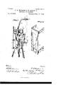
In the accompanying drawings, Figure 1 is a perspective view of our improved rock-drilling machine. Fig. 2 is a rear elevation. Fig. 3 is an enlarged side view showing the manner of operation of the device, and Fig. 4 is a detail perspective View of the guide for the plunger or lifting-clamp. Fig. 5 is a detail sectional view toshow the plunger or liftingclamp.
In carrying out our invention we provide the body or block A, which is supported on suitable legs 13, and has a transverse shaft 0 mounted at its lower end, on which a balancewheeLD is secured, the said balance-wheel E in the body.
moving through a vertical longitudinal slot On the upper end of the body we secure suitable journ al-boxes, in which the driving-shaft F is mounted, the said drivingshaft having a crank-disk G on its front end and a gear-wheel H on its rear end. This gearwheel H meshes with the driving-wheel I,
mounted on a'suitablestub-shaft on the rear side of the body, and the said driving-wheel also meshes with a pinion J on the rear end of the shaft C, so that the balance-wheel and the driving-shaft will be simultaneously rotated and an even steady mot-ion imparted to the machine.
On the front side of thebody, below the crank-disk G, we secure the guide K, which consists of a longitudinally-slotted plate,
. i slightly twisted in the direction of its length and provided with the rearwardly-projecting arms L at its ends, by means of which it is secured to the body. The plunger or liftinging the rear side of the guide and passing through the slot in the same, so as to hold the plunger to the said guide, as will be readily understood. The horizontal shorter arm of the bracket is provided with a central opening P, through which the drill-rod passes, and on the longer arm of the bracket we pivotally mounta dog Q, having a concave outer end which is adapted to engage the drill-rod.
To the upper end of the body we secure the guide-arm R, which projects upward and forward from the body, and is provided at its end with a transverse perforation in which a staple or hook S is mounted, the said staple or hook being providednvith a screw-threaded extremity, on which nuts T are mounted and adapted to be turned up against the said arm B, so as to clamp .the staple or hook around the drill-rod. A dogU is pivoted on the arm R, and is adapted to engage the rod, as clearly shown.
In practice the drill-rod is passed vertically through the staple S and the perforation P in the lifting-clamp, and the driving-wheel is then rotated so as to impart a reciprocating motion to the lifting-clamp through the driving-shaft, the crank-disk, and the pitman, as will be readily understood. On the upward movement of the lifting-clamp the dog pivoted thereto will incline downward and bind around the drill-rod, so as to raise the same. \Vhen the said clamps starts on its downward stroke,'the dog will be thrown out of engagemeutwith the drill-rod, and the said rod will then fall onto the rock, as will be readily understood. The twisted formation of the guide for the lifting-clamp causes the drillrod to make a partial turn each time it is raised, so as to cut a regular hole in the rock and prevent uneven wear on the drill-blade. When it is desired to lift the drill-rod from the ground, the dog U is thrown forward, so
operated, and which is composed of few parts, so that it can be manufactured cheaply and readily.
The advantages of our device are thought to be obvious from the foregoing description, when taken in connection with the accent panying drawings, and detailed reference thereto is deemed unnecessary.
Having thus described our invention, what We claim, and desire to secure by Letters Patent, is-
1. The combination, with the body, of the arm R, secured to the upper end thereof and projecting upward and forward therefrom, the staple mounted in the end of said arm and adapted to pass around the drill-rod, and the nuts mounted on the end. of said staple, as set forth.
2. The combinationoi' the body, the twisted THOMAS H WITIIERS. MATTHEW EDGAR, JR. Witnesses:
E. F. \VRIGHT, EMILY F. \VRIGHT,
Publications (1)
| Publication Number | Publication Date |
|---|---|
| US417618A true US417618A (en) | 1889-12-17 |
Family
ID=2486544
Family Applications (1)
| Application Number | Title | Priority Date | Filing Date |
|---|---|---|---|
| US417618D Expired - Lifetime US417618A (en) | Rock-drilling machine |
Country Status (1)
| Country | Link |
|---|---|
| US (1) | US417618A (en) |
-
0
- US US417618D patent/US417618A/en not_active Expired - Lifetime
Similar Documents
| Publication | Publication Date | Title |
|---|---|---|
| US417618A (en) | Rock-drilling machine | |
| US457552A (en) | Well-drilling machine | |
| US464612A (en) | Rock-drill | |
| US431319A (en) | Drilling-machine | |
| US569976A (en) | Bale-elevator | |
| US618341A (en) | Apparatus for drawing pump-rods from wells | |
| US488116A (en) | de la maee | |
| US1163535A (en) | Pump. | |
| US249115A (en) | Well-boring machine | |
| US569012A (en) | Well-boring machine | |
| US481482A (en) | Worth | |
| US382500A (en) | Well-drilling machine | |
| US807699A (en) | Wire line attachment for well-drilling machines. | |
| US234586A (en) | knowlan | |
| US452878A (en) | Well-drilling machine | |
| US783227A (en) | Well-drilling machine. | |
| US275855A (en) | Stump-puller | |
| US548538A (en) | Mechanism for boring and drilling wells | |
| US1423263A (en) | Cable clamp | |
| US816988A (en) | Well-drilling machine. | |
| US771036A (en) | Spudding attachment for drilling-machines. | |
| US292665A (en) | Hand rock-drilling machine | |
| US980018A (en) | Oil-well pick-up. | |
| US594064A (en) | And william t | |
| US510039A (en) | Drilling-machine |