US416640A - Half to george h - Google Patents
Half to george h Download PDFInfo
- Publication number
- US416640A US416640A US416640DA US416640A US 416640 A US416640 A US 416640A US 416640D A US416640D A US 416640DA US 416640 A US416640 A US 416640A
- Authority
- US
- United States
- Prior art keywords
- rod
- car
- head
- draw
- bumpers
- Prior art date
- Legal status (The legal status is an assumption and is not a legal conclusion. Google has not performed a legal analysis and makes no representation as to the accuracy of the status listed.)
- Expired - Lifetime
Links
- 238000010168 coupling process Methods 0.000 description 8
- 238000005859 coupling reaction Methods 0.000 description 8
- 230000008878 coupling Effects 0.000 description 5
- 208000036366 Sensation of pressure Diseases 0.000 description 1
- 238000010276 construction Methods 0.000 description 1
- 238000000034 method Methods 0.000 description 1
Images
Classifications
-
- A—HUMAN NECESSITIES
- A63—SPORTS; GAMES; AMUSEMENTS
- A63H—TOYS, e.g. TOPS, DOLLS, HOOPS OR BUILDING BLOCKS
- A63H19/00—Model railways
- A63H19/16—Parts for model railway vehicles
- A63H19/18—Car coupling or uncoupling mechanisms
Definitions
- My invention relates to the construction of car-coupling devices, and is an improvement on the coupler for which Letters Patent No. 391,719 were issued to me on the 23d day of October, 1888, and will be understood from the following description.
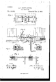
- Figure 1 represents a top View of my device connected to the ends of Fig. 2 is a side View of the same.
- Fig. 3 is a longitudinal section of the draw-head, showing the openings for the pin and link and slot for the rod 0.
- Fig. 4 is a de tail view of the rod upon which the couplinghooks are mounted, one of the bumpers and the central draw-head being in cross-section.
- Fig. 5 is a horizontal section of one of the bumpers, showing theslot through which the rod '1' passes.
- 0 is a car having bumpers b bolted to the end on each side and provided with a central draw-head Z), connectedto a draw-bar in the usual manner, as shown in Fig. .2.
- the rod 7 having upturned ends forming levers Z, is journaled in the central draw-head and passes through ,slots slformed in the bumpers b.
- This rod is rounded where it is journaled in the draw-head and where it passes through the bumpers, and its sides are squared the rest of the way.
- keyed hooks h having holes corresponding in shape with the rod, and by removing the keys the hooks may be moved along the rod, but will not turn upon it. They turn with the rod when the latter is revolved in its bearings.
- the slots .91 of the bumpers b are elongated, so as to allow the draw-head to be forced backward by contact with the adjacent car without affecting the rod 0*, and are made long enough to allow the necessary backward movement
- the drawbar has a coiled spring 819 mounted on its inner end in the usual manner. This spring takes up the recoil and tion shown at the right hand in Fig. 2.
- the hooks h are of any convenient length and are mounted on the rod 4', and whenever the leversl are turned are lifted or lowered, so that the car may be coupled or uncoupled through the action of these levers.
- the hooks h When the hooks h are not in use they may be thrown down out of the way in the posi- Here the hooks of one car are shown coupled over the rod of the next adjacent car.
- the central draw-head b is provided with a recessed opening 0, admitting an ordinary link Z, and another opening ph to admit an ordinary pin p, and this will allow the car upon which my improved coupling device has been placed to be coupled to a car having the ordinary link-and-pin coupling, or both couplingsmay be used at once, as shown in Fig. 2. i
- the elongated slot .91 may b formed in the draw-head b, as in Fig. 3, instead of the bumpers b, and in the latter an ordinary round opening, providing bearings for the rod would then be suflicient; but the former method is preferable.
- the hooks 72. should be set upon the rod 0" on either side and near to the central draw-head b, as shown in Fig. 1, and this arrangement is preferable for short curves, as the strain is thus brought along the central line of draft.
- the car-coupler herein described comprising the rod 1", squared between its bearing parts, hooks h, mounted upon the squared portions, bumpers b, having slots st to admit such rod, the central draw-head b, in which the rod 0 is journaled, having openings 0 and 19h for the ordinary link-and-pin coupling, substantially as shown and described.
- a car-coupler provided with bumpers b on each side, the central draw-head b, having slot 31 and openings 0 and 1271, for link-andpin couplings, the rod 0", carrying hooks h, mounted thereon, journaled in bearings in the bumpers b and passing through the slot 31 of the central draw-head, with means-such as levers Zconnected to such rod for operating the coupling-hooks, all combined substantially as shown and described.
- a central draw-head having openings for an ordinary link and pin, a rod journaled therein squared between its bearing-points, coupling-hooks h, mounted thereon, 'side bumpers I), having slots sl, through which such rod passes, and levers Z, formed upon one or more ends of such rod for operating the same, all combined substantially as shown and described.
Landscapes
- Shafts, Cranks, Connecting Bars, And Related Bearings (AREA)
Description
(No Model.) I
A. O. NIEDLANDER. GAR COUPLING;
No. 416,640. Patented Dec. 3. 1889.
F'. a by 1b;
mv PETERS. mwmm n m Wuhingkm. m c
I opposite cars.
UNITED STATES PATENT OFFICE.
ALLEN O. NIEDLANDER, OF INDIANAPOLIS, INDIANA, ASSIGNOR OF ONE- HALF TO GEORGE I'I. MILLER, OF SAME PLACE.
" CAR-COUPLING.
SPECIFICATION forming part of Letters Patent No. 416,640, dated December 3, 1889.
Application filed November 12, 1888. Serial No. 290,611. (No model.)
To aZZ whom it may concern:
Be it known that I, ALLEN O. NIEDLANDER, of Indianapolis, county of Marion, and State of Indiana, have invented certain new and useful Improvements in Car-Couplers; and I do hereby declare that the following is a full, clear, and exact description thereof, reference being had to the accompanying drawings, in which like letters refer to like parts.
My invention relates to the construction of car-coupling devices, and is an improvement on the coupler for which Letters Patent No. 391,719 were issued to me on the 23d day of October, 1888, and will be understood from the following description.
In the drawings, Figure 1 represents a top View of my device connected to the ends of Fig. 2 is a side View of the same. Fig. 3 is a longitudinal section of the draw-head, showing the openings for the pin and link and slot for the rod 0. Fig. 4 is a de tail view of the rod upon which the couplinghooks are mounted, one of the bumpers and the central draw-head being in cross-section. Fig. 5 is a horizontal section of one of the bumpers, showing theslot through which the rod '1' passes.
In detail, 0 is a car having bumpers b bolted to the end on each side and provided with a central draw-head Z), connectedto a draw-bar in the usual manner, as shown in Fig. .2. The rod 7", having upturned ends forming levers Z, is journaled in the central draw-head and passes through ,slots slformed in the bumpers b. This rod is rounded where it is journaled in the draw-head and where it passes through the bumpers, and its sides are squared the rest of the way. On this rod are keyed hooks h, having holes corresponding in shape with the rod, and by removing the keys the hooks may be moved along the rod, but will not turn upon it. They turn with the rod when the latter is revolved in its bearings.
The slots .91 of the bumpers b are elongated, so as to allow the draw-head to be forced backward by contact with the adjacent car without affecting the rod 0*, and are made long enough to allow the necessary backward movement The drawbar has a coiled spring 819 mounted on its inner end in the usual manner. This spring takes up the recoil and tion shown at the right hand in Fig. 2.
forces the draw-head forward when the press ure is removed. The hooks h, as has been said, are of any convenient length and are mounted on the rod 4', and whenever the leversl are turned are lifted or lowered, so that the car may be coupled or uncoupled through the action of these levers.
When the hooks h are not in use they may be thrown down out of the way in the posi- Here the hooks of one car are shown coupled over the rod of the next adjacent car.
The central draw-head b is provided with a recessed opening 0, admitting an ordinary link Z, and another opening ph to admit an ordinary pin p, and this will allow the car upon which my improved coupling device has been placed to be coupled to a car having the ordinary link-and-pin coupling, or both couplingsmay be used at once, as shown in Fig. 2. i
If desired, the elongated slot .91 may b formed in the draw-head b, as in Fig. 3, instead of the bumpers b, and in the latter an ordinary round opening, providing bearings for the rod would then be suflicient; but the former method is preferable.
In practice it is desirable that the hooks 72. should be set upon the rod 0" on either side and near to the central draw-head b, as shown in Fig. 1, and this arrangement is preferable for short curves, as the strain is thus brought along the central line of draft.
What I claim as my invention, and desire to secure by Letters Patent, is the following, V12:
1. The car-coupler herein described, comprising the rod 1", squared between its bearing parts, hooks h, mounted upon the squared portions, bumpers b, having slots st to admit such rod, the central draw-head b, in which the rod 0 is journaled, having openings 0 and 19h for the ordinary link-and-pin coupling, substantially as shown and described.
2. A car-coupler provided with bumpers b on each side, the central draw-head b, having slot 31 and openings 0 and 1271, for link-andpin couplings, the rod 0", carrying hooks h, mounted thereon, journaled in bearings in the bumpers b and passing through the slot 31 of the central draw-head, with means-such as levers Zconnected to such rod for operating the coupling-hooks, all combined substantially as shown and described.
3. In a car-coupler, a central draw-head having openings for an ordinary link and pin, a rod journaled therein squared between its bearing-points, coupling-hooks h, mounted thereon, 'side bumpers I), having slots sl, through which such rod passes, and levers Z, formed upon one or more ends of such rod for operating the same, all combined substantially as shown and described.
4:. In a car-coupling device, a car 0, having side bumpers b, with slots .91 through the same, the central draw-head I), having openings for ALLEN O. NIEDLANDER.
Witnesses:
O. P. J ACOBS, GEO. H. MILLER.
Publications (1)
| Publication Number | Publication Date |
|---|---|
| US416640A true US416640A (en) | 1889-12-03 |
Family
ID=2485567
Family Applications (1)
| Application Number | Title | Priority Date | Filing Date |
|---|---|---|---|
| US416640D Expired - Lifetime US416640A (en) | Half to george h |
Country Status (1)
| Country | Link |
|---|---|
| US (1) | US416640A (en) |
-
0
- US US416640D patent/US416640A/en not_active Expired - Lifetime
Similar Documents
| Publication | Publication Date | Title |
|---|---|---|
| US419358A (en) | raymond | |
| US416640A (en) | Half to george h | |
| US335611A (en) | Jambs franklin moorman | |
| US583548A (en) | Car-coupling | |
| US415194A (en) | Car-coupling | |
| US257780A (en) | Car-coupling | |
| US154491A (en) | Improvement in car-couplings | |
| US190984A (en) | Improvement in car-couplings | |
| US420540A (en) | Car-coupling | |
| US452356A (en) | Car-coupling | |
| US506933A (en) | Car-coupling | |
| US344127A (en) | John millee | |
| US363944A (en) | Car-coupling | |
| US491976A (en) | Car-coupling | |
| US309463A (en) | Car-coupling | |
| US436260A (en) | Car-coupling | |
| US429920A (en) | Car-coupling | |
| US165529A (en) | Improvement in car-couplings | |
| US386854A (en) | skinner | |
| US278573A (en) | Car-coupling | |
| US491698A (en) | Car-coupling | |
| US786169A (en) | Car-coupling. | |
| US433385A (en) | Car-coupling | |
| US401005A (en) | carmona y valle | |
| US436346A (en) | Joseph edward francis |