US4160868A - Apparatus and method for melting ferrous pellets - Google Patents
Apparatus and method for melting ferrous pellets Download PDFInfo
- Publication number
- US4160868A US4160868A US05/744,424 US74442476A US4160868A US 4160868 A US4160868 A US 4160868A US 74442476 A US74442476 A US 74442476A US 4160868 A US4160868 A US 4160868A
- Authority
- US
- United States
- Prior art keywords
- melt
- coils
- central portion
- pellets
- arc
- Prior art date
- Legal status (The legal status is an assumption and is not a legal conclusion. Google has not performed a legal analysis and makes no representation as to the accuracy of the status listed.)
- Expired - Lifetime
Links
- 239000008188 pellet Substances 0.000 title claims abstract description 22
- CWYNVVGOOAEACU-UHFFFAOYSA-N Fe2+ Chemical compound [Fe+2] CWYNVVGOOAEACU-UHFFFAOYSA-N 0.000 title claims abstract description 9
- 238000002844 melting Methods 0.000 title claims description 4
- 230000008018 melting Effects 0.000 title claims description 4
- 238000000034 method Methods 0.000 title 1
- 239000000155 melt Substances 0.000 claims abstract description 30
- 238000000819 phase cycle Methods 0.000 claims description 2
- 239000002893 slag Substances 0.000 abstract description 22
- 238000010891 electric arc Methods 0.000 abstract description 5
- XEEYBQQBJWHFJM-UHFFFAOYSA-N Iron Chemical compound [Fe] XEEYBQQBJWHFJM-UHFFFAOYSA-N 0.000 description 10
- 238000003756 stirring Methods 0.000 description 8
- 230000002441 reversible effect Effects 0.000 description 6
- 229910052742 iron Inorganic materials 0.000 description 5
- 239000004020 conductor Substances 0.000 description 3
- 238000010276 construction Methods 0.000 description 3
- 230000000694 effects Effects 0.000 description 3
- 230000005855 radiation Effects 0.000 description 3
- 239000002184 metal Substances 0.000 description 2
- 229910052751 metal Inorganic materials 0.000 description 2
- 230000015572 biosynthetic process Effects 0.000 description 1
- 230000005684 electric field Effects 0.000 description 1
- 238000005755 formation reaction Methods 0.000 description 1
- 230000006698 induction Effects 0.000 description 1
- 230000001939 inductive effect Effects 0.000 description 1
- 230000003647 oxidation Effects 0.000 description 1
- 238000007254 oxidation reaction Methods 0.000 description 1
- 238000010405 reoxidation reaction Methods 0.000 description 1
Images
Classifications
-
- C—CHEMISTRY; METALLURGY
- C21—METALLURGY OF IRON
- C21C—PROCESSING OF PIG-IRON, e.g. REFINING, MANUFACTURE OF WROUGHT-IRON OR STEEL; TREATMENT IN MOLTEN STATE OF FERROUS ALLOYS
- C21C5/00—Manufacture of carbon-steel, e.g. plain mild steel, medium carbon steel or cast steel or stainless steel
- C21C5/52—Manufacture of steel in electric furnaces
-
- Y—GENERAL TAGGING OF NEW TECHNOLOGICAL DEVELOPMENTS; GENERAL TAGGING OF CROSS-SECTIONAL TECHNOLOGIES SPANNING OVER SEVERAL SECTIONS OF THE IPC; TECHNICAL SUBJECTS COVERED BY FORMER USPC CROSS-REFERENCE ART COLLECTIONS [XRACs] AND DIGESTS
- Y02—TECHNOLOGIES OR APPLICATIONS FOR MITIGATION OR ADAPTATION AGAINST CLIMATE CHANGE
- Y02P—CLIMATE CHANGE MITIGATION TECHNOLOGIES IN THE PRODUCTION OR PROCESSING OF GOODS
- Y02P10/00—Technologies related to metal processing
- Y02P10/20—Recycling
Definitions
- Iron sponge containing prereduced iron ore is pelletized into pellets which are melted by the pellets being fed to an iron melt in the hearth of an electric arc furnace conventionally constructed with the typical cylindrical shape and having one or more centrally psoitioned arcing electrodes.
- the arc or arcs formed between the electrodes and the melt may be powered by either AC or DC.
- the pellets floating on the melt tend to form a crust and to become oxidized, or in effect reoxidized, which interferes with the desired rapid melting of the pellets.
- the arc or arcs drive this slag radially outwardly to expose the melt centrally within the furnace, which is desirable because it permits the pellets to fall on clean molten metal if the pellets go where they are aimed.
- This action of the arc or arcs has the undesirable effect of not only driving away the slag, but also the pellets, not only resulting in the problem of the crust formation and oxidation or reoxidation of the pellets, but also having the undesirable effect of producing a thickened slag layer at the furnace's slag line and thus increasing the normal attack of the slag on the furnace wall lining.
- the slag layer is thinned centrally around the arc or arcs, thus exposing the furnace wall lining to direct radiation from the arc or arcs, to an undesirable degree.
- Electric arc furnaces have been provided with electric inductive stirrers positioned below the bottom of the hearth, the hearth being made with a non-magnetic construction.
- Such a stirrer is in the form of a flat coil or coils which can be powered with multiphase AC to inductively stir the melt in the hearth.
- Such stirrers have been ineffective insofar as any correction of the above described troubles is concerned.
- an electric arc furnace having the usual hearth with its upstanding periphery containing the ferrous melt, and at least one arcing electrode positioned to form the arc with the melt above the central portion of the hearth and melt. Also, an electric induction stirrer is used, the hearth being non-magnetic.
- the stirrer of the present invention is constructed to inductively stir the melt so that its lower and upper portions flow radially respectively in opposite directions between the central portion of the melt and hearth and the upstanding periphery of the hearth.
- This new stirrer comprises at least two substantially concentric radially inner and outer conductor coils positioned beneath the hearth substantially parallel therewith and substantially symmetrically with respect to the central portion where the arcing occurs.
- the two coils are provided with an AC power means for feeding them with multiphase current having a phase sequence inductively causing the described stirring.
- the traveling field in one coil is made opposite to that of the other coil, thus providing the described new stirring.
- the traveling fields are made reversible with respect to each other.
- the stirring direction is such that it is the upper melt portion and the melt surface that is inductively fed radially inwardly from the hearth's upstanding periphery to the arcing location.
- the inwardly flowing melt then moves everything on its surface, pellets and slag, towards the arcing location, the pellets being rapidly melted by the heat of the arc or arcs and/or by reaching the clean melt at the central portion of the furnace.
- the slag layer at the slag line of the furnace wall lining is reduced in thickness with a consequent reduction in the slag's attack on the furnace lining at the slag line.
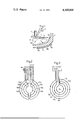
- FIG. 1 is a cross section of one half of an electric arc furnace, showing only the parts required for an understanding of this invention
- FIG. 2 diagrammatically shows a first example of the new stirrer
- FIG. 3 is a corresponding manner shows a second example.
- FIG. 1 shows the arcing electrode 1 and a pellet feeder 2 feeding the ferrous pellets 2a in the form of pelletized iron sponge containing prereduced iron ore, to the arc 3 insofar as this is possible.
- the ferrous melt M heated by the arc 3 is contained by the nonmagnetic hearth 8 having the upstanding periphery 10 from which the furnace wall lining 4 extends upwardly.
- the surface of the melt M is shown at 9 with a layer of slag 11 floating on this surface.
- the hearth 9 is of non-magnetic construction.
- the furnace is of generally cylindrical construction with the arcing electrode 1 centrally positioned. More than one electrode may be used to form more of the arcs 3 but all of the arcs are substantially centrally positioned in the furnace.
- the arcing power may be either AC or DC.
- the melt M is stirred as indicated by the arrow 5, in this case the direction being radially outwardly from the central portion throughout the lower portion of the melt, and radially inwardly throughout the melt's upper portion and surface 9.
- Possible displaced pellets are therefore fed to the arc 3 and the naked metal there, while the slag 11 forms an annular pile or thickened layer surrounding the arc, thereby becoming thinned at the periphery 10 of the hearth which by its junction with the furnace wall 4 forms the normal slag line.
- FIG. 1 not only the slag, but the melt itself is dragged away from the slag line by the stirring action of the present invention.
- the slag 11 is carried towards the periphery of the hearth to facilitate deslagging through the usual slag tap hole (not illustrated).
- FIG. 1 shows an inner coil or pair 6a and 7a, and an outer coil or pair 6b and 7b. These coils may be made as a flat assembly following the contour of the hearth bottom and in that sense parallel to the bottom.
- FIG. 3 shows the example used in FIG. 1.
- the coils are radially interspaced and are concentric with each other, and they are symmetrically arranged with respect to the central portion of the furnace, or in other words, with respect to the electrode 1 and its arc 3.
- the coils are shown as being powered from a multiphase current source providing the coils with the oppositely rotating fields indicated by the arrows in FIG. 3, due to their series arrangement.
- the coil 6a is in series connection with the coil 6b
- the coil 7a is in series connection with the coil 7b. Therefore, the electric fields of the coils 6a and 7a are in the same direction while being in the opposite direction as to the coils 6b and 7b.
- the coils 6a and 7a through their induced currents in the melt propel the lower portion of the melt radially outwardly while the coils 6b and 7b apply a propulsion force in the opposite direction, the result being that the radially outward flow of melt at the circumferential position established by the coil pair 6b and 7b, is caused to reverse, the result being that the flow loops upwardly and back on itself and flows annularly throughout the upper portion of the melt and its surface 9 to the central portion where the arc or arcs 3 are operating.
- the innermost one of the coils has a central or center area 6c encircled by the coil pair 6a and 7a and which is free from any conductors.
- the area directly below the arc or arcs 3, or in other words, the central portion of the melt is substantially free from induced currents. Therefore, as the upper portion of the melt flows radially towards its central portion, the flow at that location inherently descends to join the lower portion which is being driven radially outwardly by the coils 6a and 7a.
- the traveling electric multiphase currents applied to the coils 6a and 7a and 6b and 7b may be applied in the conventional manner used to induce traveling currents in the melt.
- FIG. 2 serves to show that the coils 6a and 8a of FIG. 3 can be provided by a pair of half coils shown at 12a and 13a and 12a' and 13a' in FIG. 2.
- the outer coil pair 6b and 7b of FIG. 2 are replaced by the outer half coils 12b and 13b and 12b' and 13b' in FIG. 2.
- the series connections of the coils are effected by the respective coils being interconnected in the form of flat loops.
- the coils 6a and 6b are connected in series by the radially extending connector 6d, while the coils 7a and 7b are interconnected by the radially extending conductor 7c. In this way the traveling fields of the coils 6a and 7a are in the same direction while the corresponding fields for the coils 6b and 7b are in the opposite direction.
- the coils 6a and 7a or their equivalent half coils in FIG. 2 serve to drive the melt, radially outwardly from the location of the arc or arcs, throughout the lower portion of the melt, while the reverse action coils 6b and 7b, or their equivalent half coils in FIG. 2, provide a reverse drive causing the melt to bend or loop upwardly to the upper portion of the melt and its surface, with the result that the flow is then radially inwardly to achieve the objective of the present invention.
- FIG. 2 serves to show both that the inner and outer concentric coils of this invention may be made as half coils, and that by the reverse connection switch it is possible to reverse the melt flow.
Landscapes
- Engineering & Computer Science (AREA)
- Chemical & Material Sciences (AREA)
- Manufacturing & Machinery (AREA)
- Materials Engineering (AREA)
- Metallurgy (AREA)
- Organic Chemistry (AREA)
- Vertical, Hearth, Or Arc Furnaces (AREA)
- Furnace Details (AREA)
- Discharge Heating (AREA)
Applications Claiming Priority (2)
| Application Number | Priority Date | Filing Date | Title |
|---|---|---|---|
| SE7513411 | 1975-11-28 | ||
| SE7513411A SE7513411L (sv) | 1975-11-28 | 1975-11-28 | Forfaringssett for smeltning av pellets eller styckeformigt gods, innehallande jern, samt induktiv omrorare vid ljusbagsugnar for utforande av detta forfaringssett |
Publications (1)
| Publication Number | Publication Date |
|---|---|
| US4160868A true US4160868A (en) | 1979-07-10 |
Family
ID=20326183
Family Applications (1)
| Application Number | Title | Priority Date | Filing Date |
|---|---|---|---|
| US05/744,424 Expired - Lifetime US4160868A (en) | 1975-11-28 | 1976-11-23 | Apparatus and method for melting ferrous pellets |
Country Status (5)
| Country | Link |
|---|---|
| US (1) | US4160868A (cg-RX-API-DMAC7.html) |
| JP (1) | JPS5267830A (cg-RX-API-DMAC7.html) |
| DE (1) | DE2651934A1 (cg-RX-API-DMAC7.html) |
| FR (1) | FR2333046A1 (cg-RX-API-DMAC7.html) |
| SE (1) | SE7513411L (cg-RX-API-DMAC7.html) |
Cited By (1)
| Publication number | Priority date | Publication date | Assignee | Title |
|---|---|---|---|---|
| US5375139A (en) * | 1993-02-26 | 1994-12-20 | Bender; Manfred | Electric arc furnace insitu scrap preheating process |
Families Citing this family (1)
| Publication number | Priority date | Publication date | Assignee | Title |
|---|---|---|---|---|
| PL2616560T3 (pl) * | 2010-09-14 | 2014-05-30 | Abb Research Ltd | Urządzenie i sposób mieszania elektromagnetycznego w elektrycznym piecu łukowym |
Citations (5)
| Publication number | Priority date | Publication date | Assignee | Title |
|---|---|---|---|---|
| US2256518A (en) * | 1938-10-03 | 1941-09-23 | Asea Ab | Electric furnace |
| DE1960327A1 (cg-RX-API-DMAC7.html) * | 1969-12-02 | 1971-04-22 | ||
| US3709476A (en) * | 1970-07-15 | 1973-01-09 | P Hammarlund | Means for inductive stirring |
| SU395394A1 (ru) * | 1972-04-10 | 1973-08-28 | ГАРНИССАЖНЫЙ ТИГЕЛЬ•' ?Т'Г,''• и Ц '4Kii-!t;vlJ;.• !1ГГ-и | |
| US3988525A (en) * | 1974-05-21 | 1976-10-26 | Allmanna Svenska Elektriska Aktiebolaget | Direct current arc furnace with charging means |
Family Cites Families (3)
| Publication number | Priority date | Publication date | Assignee | Title |
|---|---|---|---|---|
| FR1018193A (fr) * | 1949-05-24 | 1952-12-29 | Asea Ab | Four métallurgique à enroulement remueur |
| US3579324A (en) * | 1968-11-18 | 1971-05-18 | Inductotherm Corp | Method for induction melting of fine particles |
| US3715200A (en) * | 1969-02-17 | 1973-02-06 | Falconbridge Nickel Mines Ltd | Electric arc furnace operation |
-
1975
- 1975-11-28 SE SE7513411A patent/SE7513411L/ not_active Application Discontinuation
-
1976
- 1976-11-13 DE DE19762651934 patent/DE2651934A1/de not_active Withdrawn
- 1976-11-23 US US05/744,424 patent/US4160868A/en not_active Expired - Lifetime
- 1976-11-24 JP JP51141068A patent/JPS5267830A/ja active Granted
- 1976-11-25 FR FR7635518A patent/FR2333046A1/fr active Granted
Patent Citations (5)
| Publication number | Priority date | Publication date | Assignee | Title |
|---|---|---|---|---|
| US2256518A (en) * | 1938-10-03 | 1941-09-23 | Asea Ab | Electric furnace |
| DE1960327A1 (cg-RX-API-DMAC7.html) * | 1969-12-02 | 1971-04-22 | ||
| US3709476A (en) * | 1970-07-15 | 1973-01-09 | P Hammarlund | Means for inductive stirring |
| SU395394A1 (ru) * | 1972-04-10 | 1973-08-28 | ГАРНИССАЖНЫЙ ТИГЕЛЬ•' ?Т'Г,''• и Ц '4Kii-!t;vlJ;.• !1ГГ-и | |
| US3988525A (en) * | 1974-05-21 | 1976-10-26 | Allmanna Svenska Elektriska Aktiebolaget | Direct current arc furnace with charging means |
Cited By (1)
| Publication number | Priority date | Publication date | Assignee | Title |
|---|---|---|---|---|
| US5375139A (en) * | 1993-02-26 | 1994-12-20 | Bender; Manfred | Electric arc furnace insitu scrap preheating process |
Also Published As
| Publication number | Publication date |
|---|---|
| JPS5624357B2 (cg-RX-API-DMAC7.html) | 1981-06-05 |
| DE2651934A1 (de) | 1977-06-02 |
| FR2333046B1 (cg-RX-API-DMAC7.html) | 1980-12-12 |
| SE7513411L (sv) | 1977-05-28 |
| JPS5267830A (en) | 1977-06-04 |
| FR2333046A1 (fr) | 1977-06-24 |
Similar Documents
| Publication | Publication Date | Title |
|---|---|---|
| US4149024A (en) | Arc furnace for reducing metal oxides and method for operating such a furnace | |
| US4110546A (en) | DC arc furnace having a rotating arc | |
| US2363582A (en) | Method of and means for stirring or circulating molten or liquid materials or mediums | |
| US4495625A (en) | Magnetic field stabilized transferred arc furnace | |
| SU682141A3 (ru) | Способ производства углеродистого металлического расплава | |
| US2686823A (en) | Rotary electric field fluid stirring apparatus | |
| US3947621A (en) | Furnace and method for reducing metal oxides to molten metal | |
| US4160868A (en) | Apparatus and method for melting ferrous pellets | |
| FI79560B (fi) | Smaeltugn och foerfarande foer chargering av det material, som behandlas, in i den. | |
| GB1579562A (en) | Furnace and method for melting metallic material | |
| JPS5966684A (ja) | とりべ炉を運転する方法 | |
| JP7026693B2 (ja) | 金属製造プロセスのための炉アセンブリ | |
| US2139853A (en) | Method of making steel | |
| US3988525A (en) | Direct current arc furnace with charging means | |
| US1940622A (en) | Electric induction furnace method | |
| JPH03233289A (ja) | 直流アーク炉 | |
| US4071687A (en) | Electric arc furnace for continuous melting of directly reduced iron or directly reduced iron ore | |
| US4034146A (en) | Method and apparatus for equalizing the wall lining wear in three phase alternating current electric arc furnaces | |
| US2097344A (en) | Metallurgical slag reaction | |
| US2262887A (en) | Manufacture of ferrous metals | |
| US1404734A (en) | Electric furnace | |
| Marchner et al. | Apparatus and Method for Melting Ferrous Pellets | |
| US5189682A (en) | Method for increasing the efficiency of a direct current electric arc furnace | |
| RU2120202C1 (ru) | Индукционная печь канального типа | |
| Bibby | Developments in electric iron and steel furnaces |