US4160692A - Wiped film evaporators - Google Patents
Wiped film evaporators Download PDFInfo
- Publication number
- US4160692A US4160692A US05/817,003 US81700377A US4160692A US 4160692 A US4160692 A US 4160692A US 81700377 A US81700377 A US 81700377A US 4160692 A US4160692 A US 4160692A
- Authority
- US
- United States
- Prior art keywords
- vessel
- evaporator
- wiping
- evaporator according
- corrosion resistant
- Prior art date
- Legal status (The legal status is an assumption and is not a legal conclusion. Google has not performed a legal analysis and makes no representation as to the accuracy of the status listed.)
- Expired - Lifetime
Links
- 239000007788 liquid Substances 0.000 claims abstract description 45
- 238000005260 corrosion Methods 0.000 claims abstract description 21
- 230000007797 corrosion Effects 0.000 claims abstract description 21
- 239000011521 glass Substances 0.000 claims abstract description 18
- NBVXSUQYWXRMNV-UHFFFAOYSA-N fluoromethane Chemical compound FC NBVXSUQYWXRMNV-UHFFFAOYSA-N 0.000 claims abstract description 4
- 238000007789 sealing Methods 0.000 claims description 5
- 230000015572 biosynthetic process Effects 0.000 claims description 4
- -1 polytetrafluoroethylene Polymers 0.000 claims 1
- 229920001343 polytetrafluoroethylene Polymers 0.000 claims 1
- 239000004810 polytetrafluoroethylene Substances 0.000 claims 1
- 230000000712 assembly Effects 0.000 abstract description 12
- 238000000429 assembly Methods 0.000 abstract description 12
- 238000010438 heat treatment Methods 0.000 abstract description 8
- 239000000463 material Substances 0.000 abstract description 5
- 210000003298 dental enamel Anatomy 0.000 abstract 1
- 239000010408 film Substances 0.000 description 14
- 238000000034 method Methods 0.000 description 7
- 230000008569 process Effects 0.000 description 6
- 229910000831 Steel Inorganic materials 0.000 description 5
- 238000001704 evaporation Methods 0.000 description 5
- 230000008020 evaporation Effects 0.000 description 5
- 239000010959 steel Substances 0.000 description 5
- 239000000956 alloy Substances 0.000 description 4
- 229910045601 alloy Inorganic materials 0.000 description 4
- 230000002093 peripheral effect Effects 0.000 description 4
- 230000008439 repair process Effects 0.000 description 3
- 239000000126 substance Substances 0.000 description 3
- 239000007864 aqueous solution Substances 0.000 description 2
- 230000008901 benefit Effects 0.000 description 2
- 238000001311 chemical methods and process Methods 0.000 description 2
- 238000013461 design Methods 0.000 description 2
- 238000007599 discharging Methods 0.000 description 2
- 238000003780 insertion Methods 0.000 description 2
- 230000037431 insertion Effects 0.000 description 2
- 238000004519 manufacturing process Methods 0.000 description 2
- 230000004048 modification Effects 0.000 description 2
- 238000012986 modification Methods 0.000 description 2
- 239000002245 particle Substances 0.000 description 2
- 239000004033 plastic Substances 0.000 description 2
- 229920003023 plastic Polymers 0.000 description 2
- 230000000284 resting effect Effects 0.000 description 2
- 239000002253 acid Substances 0.000 description 1
- 239000003513 alkali Substances 0.000 description 1
- 239000002585 base Substances 0.000 description 1
- 238000009835 boiling Methods 0.000 description 1
- 239000005388 borosilicate glass Substances 0.000 description 1
- 239000000919 ceramic Substances 0.000 description 1
- 238000004140 cleaning Methods 0.000 description 1
- 239000011248 coating agent Substances 0.000 description 1
- 238000000576 coating method Methods 0.000 description 1
- 230000000295 complement effect Effects 0.000 description 1
- 238000010276 construction Methods 0.000 description 1
- 230000008878 coupling Effects 0.000 description 1
- 238000010168 coupling process Methods 0.000 description 1
- 238000005859 coupling reaction Methods 0.000 description 1
- 230000001419 dependent effect Effects 0.000 description 1
- 230000001627 detrimental effect Effects 0.000 description 1
- 238000009826 distribution Methods 0.000 description 1
- 238000010304 firing Methods 0.000 description 1
- 239000000796 flavoring agent Substances 0.000 description 1
- 235000019634 flavors Nutrition 0.000 description 1
- 239000012530 fluid Substances 0.000 description 1
- 230000004907 flux Effects 0.000 description 1
- 230000005484 gravity Effects 0.000 description 1
- 238000011065 in-situ storage Methods 0.000 description 1
- 238000009434 installation Methods 0.000 description 1
- 238000012423 maintenance Methods 0.000 description 1
- QSHDDOUJBYECFT-UHFFFAOYSA-N mercury Chemical compound [Hg] QSHDDOUJBYECFT-UHFFFAOYSA-N 0.000 description 1
- 229910052753 mercury Inorganic materials 0.000 description 1
- 239000000203 mixture Substances 0.000 description 1
- 150000002894 organic compounds Chemical class 0.000 description 1
- 239000011236 particulate material Substances 0.000 description 1
- 238000011084 recovery Methods 0.000 description 1
- 239000002904 solvent Substances 0.000 description 1
- 239000010935 stainless steel Substances 0.000 description 1
- 229910001220 stainless steel Inorganic materials 0.000 description 1
- 239000000758 substrate Substances 0.000 description 1
- 239000010409 thin film Substances 0.000 description 1
- 238000012546 transfer Methods 0.000 description 1
Images


Classifications
-
- B—PERFORMING OPERATIONS; TRANSPORTING
- B01—PHYSICAL OR CHEMICAL PROCESSES OR APPARATUS IN GENERAL
- B01D—SEPARATION
- B01D1/00—Evaporating
- B01D1/22—Evaporating by bringing a thin layer of the liquid into contact with a heated surface
- B01D1/222—In rotating vessels; vessels with movable parts
- B01D1/223—In rotating vessels; vessels with movable parts containing a rotor
- B01D1/225—In rotating vessels; vessels with movable parts containing a rotor with blades or scrapers
-
- Y—GENERAL TAGGING OF NEW TECHNOLOGICAL DEVELOPMENTS; GENERAL TAGGING OF CROSS-SECTIONAL TECHNOLOGIES SPANNING OVER SEVERAL SECTIONS OF THE IPC; TECHNICAL SUBJECTS COVERED BY FORMER USPC CROSS-REFERENCE ART COLLECTIONS [XRACs] AND DIGESTS
- Y10—TECHNICAL SUBJECTS COVERED BY FORMER USPC
- Y10S—TECHNICAL SUBJECTS COVERED BY FORMER USPC CROSS-REFERENCE ART COLLECTIONS [XRACs] AND DIGESTS
- Y10S159/00—Concentrating evaporators
- Y10S159/15—Special material
Definitions
- the present invention relates to wiped-film evaporators, and especially to such evaporators for use with corrosive liquids.
- wiped-film evaporator a thin film of liquid to be evaporated is formed on the internal wall of an upright cylindrical evaporation vessel by means of wiping elements carried by a rotary vertical shaft in the vessel, and heating means cause evaporation of the film.
- wiping elements carried by a rotary vertical shaft in the vessel, and heating means cause evaporation of the film.
- the wiping elements provide a rapidly changing film by fluid friction, and good heat transfer rates are maintained over the entire length of the evaporator because the wiper elements effectively wipe the entire heating surface irrespective of the film thickness.
- the wiped film evaporator can be used for evaporation of organic compounds, concentration of aqueous solutions, solvent recovery, stripping of aqueous solutions, and concentration of viscous products.
- alloys such as for example stainless steel
- parts of the evaporator coming into contact with the corrosive liquids and/or products of the process include the vessel, shaft and wiping element support means: the wiping elements themselves can be made of a plastics material.
- the manufacture of parts from alloys is relatively expensive and further alloy parts are not completely satisfactory for some processes, for example those operating at higher temperature, those with higher purity requirements and those dealing with more corrosive liquid or products.
- the alloy parts could contaminate the product, and cleaning may be difficult.
- the evaporator comprises a vertically oriented cylindrical vessel having its inner surface of corrosion resistant material; rotary shaft means within the vessel supported in bearing means and connectible to a drive, said rotary shaft means having a corrosion resistant glass lining thereon; an inlet for delivery of liquid to be evaporated into the cylindrical vessel; an outlet for vapour; and corrosion resistant wiping means carried by the rotary shaft means to wipe the internal wall surface of the cylindrical vessel for the formation of a liquid film on said internal surface, at least part of the corrosion resistant wiping means having a corrosion resistant glass lining thereon.
- the evaporator comprises a vertically oriented cylindrical evaporation vessel; rotary shaft means within the vessel and supported by bearing means located outwith the vessel with one end of the shaft means free within the vessel; an inlet for delivery of liquid to be evaporated into the cylindrical vessel; an outlet for vapour; and wiping means carried by the rotary shaft means for wiping the internal surface of the cylindrical vessel for the formation of a liquid film on said internal surface, said wiping means including a wiper assembly comprising an axial series of wiper elements individually pivotal on a rod member, the wiper elements being engageable with the internal surface of the vessel so as to have a trailing configuration to cater for irregularities in the roundness and straightness of the portion of said internal surface wiped by the wiping means.
- glassing or "glass lining” covers the bonding of a vitreous or partially devitrified inorganic coating to a metallic substrate at a suitable elevated temperature.
- FIG. 1 is a cross-sectional elevational view of a wiped-film evaporator according to one embodiment of the present invention
- FIG. 2 is a cross-sectional elevational view of a detail of FIG. 1 to a larger scale
- FIG. 3 is a plan view of the evaporator distributor of FIG. 2;
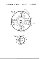
- FIG. 4 is a plan view of the evaporator of FIG. 1 through section X--X in FIG. 1 and showing the mounting of the demister plate;
- FIG. 5 is a schematic plan view of the evaporator, with a modified form of wiper element tip, and showing the movements of the wiper elements;
- FIGS. 6 and 7 show various forms of sealing connection between the parts of the evaporator vessel
- FIG. 8 shows a cross-sectional plan view of the evaporator along line B--B in FIG. 1 but with a modified liquid distribution system
- FIG. 9 shows a cross-sectional elevation of a wiped film evaporator according to a second embodiment of the present invention.
- a wiped-film evaporator 1 for use in handling corrosive liquids in chemical processes comprises a cylindrical steel vessel, housing a rotor assembly 3, a drive unit 8 for the rotor assembly 3, wiper blade assemblies 4 carried by the rotor assembly 3 for the formation of a liquid film on the inner wall 5 of the vessel 2, an inlet feed system 6 (which will be described in greater detail below) for liquid to be evaporated delivering on to the inner wall 5, an outlet 7 for vapour, a heating jacket 9 for the vessel, and a discharge 10 for non-vaporised products.
- the wiper blade assemblies 4 are axially and circumferentially staggered for complete and effective wiping of a lower portion of the wall 5 adjacent the jacket 9. As can be seen in FIG. 1, the wiper assemblies 4 extend above the zone of the heating jacket 9 so that the liquid film is formed on the wall by the assemblies 4 prior to the heating zone.
- the vessel 2 is located vertically and comprises main elongate cylindrical portion 2A, a domed top cap 2B and a generally frusto-conical bottom 2C.
- the vessel 2 is intended for operation under vacuum (e.g. 1 mm mercury abs) and the top cap 2B and bottom 2C are joined to the main portion 2A by peripheral air-tight connections 11 (two alternatives are shown in detail in FIGS. 6 and 7) each comprising annular flanges 12, 13 having axial male-and-female interfitting parts, a sealing gasket 14 and one or more sealing O-rings 15, the flanges being tightly coupled by clamping means (not shown).
- a peripheral sealing sleeve 16 for the flange interface can also be provided.
- the inner wall 5 has a corrosion resistant glass lining thereon, which lining can be formed using conventional glassing techniques.
- 7A is a demister plate and a lower heating jacket 9B serves to maintain product outflow.
- the plate 7A is supported by a lower P.T.F.E. stud 75 carried by glassed bar 74 removably located in a radical bore 72 of the vessel 2, and a glassed rod 70 extending between P.T.F.E. plugs 71 in opposed bores 72 serves for upper support of the plate 7A.
- Flange plates 73 close the outer ends of bores 72.
- the rotor assembly 3 includes a shaft 17 which extends through an opening 18 of the vessel 2 and a coupling 21 connects the shaft 17 to the motor drive-unit 8 which is supported on cap 2B by means of stool 8A.
- Support bearings 19A, 19B in the drive unit 8 serve for axial support of the shaft 17, at least one bearing 19B being a radial thrust bearing, and the shaft 17 hangs in the vessel 2, with the lower end of the shaft 17 within the vessel 2.
- the upper end of the shaft 17 is journalled in a radial seal bearing 19C located in housing 20 and a corrosion resistant (ceramic) shaft seal is located at the vessel nozzle 18.
- the hung rotor 3 can be provided with suitable rigidity and freedom from excess lateral deflection to permit satisfactory operation of the rotor 3 and wiper assemblies 4. Consequently the normal internal lower bearing for the rotor assembly can be dispensed with and this greatly facilitates the provision of an evaporator suitable for handling corrosive liquids since an internal bearing is subject to rapid wear due to the corrosive environment in the vessel.
- the rotor assembly 3 has an axial and circumferential series of radial arms 22 and this assembly 3 is glass lined (3A) to resist corrosive attack. It is a characteristic feature of this evaporator that all the edges of the rotor assembly 3 are substantially radiused 23; this permits satisfactory glassing of the rotor assembly.
- This glass lining 3A on the shaft 17 extends substantially to the upper end of the shaft 17, so that all portions of the rotor assembly 3 within the vessel 2 have a lining of corrosion resistant glass.
- a radially extending plate 24 (FIGS. 2 and 3) is welded to each straight arm 22 and has a removable fender ring 24A, the plate 24 including an axial through-bore 33.
- the glass linings 3A of arms 22 and plates 24 are shown in FIG. 2, and the substantial radiusing of the edges will be evident in this Figure.
- the through-bores 33 receive socket members 25 which include a tubular part 35 insertable into the bore 33 and a shouldered part 26 engageable with the plate 24 to locate the member 25.
- the members 25 are of glass filled P.T.F.E. and a blind bore 37 of each member 25 receives the respective end of wiper rod 28 of the wiper assemblies.
- Each wiper assembly 4 comprises a steel wiper rod 28 having glass lining 28A, and an axial series of P.T.F.E. finger elements 29 pivotally carried by the rod 28, washers 30 serving to provide tip clearance (e.g., 1 mm) between successive elements 29.
- the tips of elements 29 are square ended and the side walls of each element 29 are recessed at 31 to provide greater clearance (4 to 5 mm) to resist any fouling between the elements.
- the bore 37 of the top socket member 25 is in the open state (plug 27 removed) and the rod 28 is inserted through this top member 25.
- the wiper assemblies 4 have a staggered axial and circumferential relationship so that the portion of wall 5 adjacent heating jacket 9 is completely and effectively wiped.
- elements 29B and 29C have pivoted to cater for maximum distortion on either side of the nominal radius, 29B to a maximum radius and 29C to a minimum radius.
- the pivotal elements 29 also permit discrepencies in the radial lengths of arms 22.
- the out-of-roundness distortion may be as much as 3% of the vessel's diameter.
- Straightness distortion is catered for by pivoting of the elements 29 of each assembly 4 relative to each other.
- the number of elements 29 in each assembly 4 can vary but will be dependent on the particular application of the evaporator and especially on the particular process requirements, e.g., the chemical being processed with the degree of wiping to give good evaporation.
- the inlet feed system 6 includes a rotary distributor as described and claimed in U.S. patent application No. 808,118 filed June 20, 1977 by E. Nunlist and J. Mitchell and entitled "Feed Distributor for Glassed Steel Wiped Evaporator.”
- the feed system 6 includes an annular open-topped housing 40 surrounding the shaft 17 and resting on the upper radial arms 22 of the uppermost wiper assembly 4 and on a shorter pair of radial arms 42.
- the housing 40 is machined from a fluorocarbon block, such as P.T.F.E., and is clamped to the arms 22, 42 by means of a pair of P.T.F.E. half-rings 43, P.T.F.E. screws 44 linking the half-ring 43 and the housing 40.
- the housing 40 provides an annular chamber 45, and an inlet pipe 41 (FIG. 1) supplies liquid to be evaporated to the chamber 45.
- tubular conduits 46 of P.T.F.E. are screwed into bores 47 in the peripheral wall of the housing 40 and extend radially so that their outer ends lie closely adjacent the inner wall 5 of the vessel.
- Support plugs 48 resting in the upper sockets 25 serve for outer support of the conduits 46.
- the housing 40 has an inwardly inclined lip 49 to preclude splashing.
- the outer ends of the conduits 46 are of open-topped trough form 50: this form of conduit enables the feed system to handle particulate material.
- the rotating conduits 46 discharge the liquid on to the vessel wall 5 ahead of the uppermost blade assembly, by means of centrifugal force. It would be possible to have the conduits 46 inclined downwardly slightly so that liquid discharge is assisted by gravity. Additionally the housing 40 could be supported by the shaft 17 clear of the uppermost wiper assembly 4 and the conduits 46 could wholly comprise open-topped troughs.
- the inlet feed system 6 comprises at least one feed tray 60 (two diametrically opposed trays are used in this embodiment) with the inlet pipe 41 discharging on to the tray 60 so as to mitigate splashing.
- the tray 60 which includes a base 62 and a peripheral wall 63 can be made of P.T.F.E., and a pair of steel support arms 64 carry the tray 60.
- the inner wall-facing edge 65 of the tray is profiled complementary to the wall 5 but has a portion spaced from the wall 5 to provide a liquid feed gap G.
- the portions of the steel support arms 64 within the vessel 2 are glass lined to resist corrosive attack, and it is a feature of the trays and support arms that they are removable from the vessel wall for repair. Specifically, the arms 64 are secured externally of the vessel to satisfy the design limitations resulting from the internal glassing.
- the tray 60 can be secured by pin or pins 49 which can be of suitable plastics material.
- the rotor assembly 93 is upstanding from the bottom 2C of the vessel and is supported at the bottom in a suitably externally located thrust and journal bearing assembly 94, the upper end of the rotor assembly 93 being free within the vessel 2. Additionally, the motor 8 for the rotor assembly 93 is located below the vessel 2. Otherwise, like parts of the evaporator of FIG. 9 have the same reference numerals as in FIG. 1.
- the distributor 40 is located at the upper free end of the rotor assembly and is substantially similar to the distributor of the FIG. 1 embodiment: again the distributor is carried by the arms 22 (and 42). However, the housing 40 can be substantially cup-shaped, with the inlet feed pipe 41 discharging into the centre of the cup. Although it would be possible to have a top located axial outlet with demister elements to block liquid particle passage.
- vapour discharge 7 is located transversely to the evaporator since this conveniences the positioning of a baffle (7A) to block the passage of liquid particles to the discharge.
- a baffle (7A) to block the passage of liquid particles to the discharge.
- the rotor supported in an upper external bearing as in the FIG. 1 arrangement extra length of shafting is required for the distance between the upper bearing and the upper wiper assembly, i.e., the rotor 3 has a non-supporting portion extending passed outlet 7.
- the FIG. 10 arrangement has the advantage of eliminating this extra shafting length, and this enables considerable economies to be achieved.
- the arrangement and installation of the rotary distributor 6 is made simpler and more satisfactory, particularly since a central through-bored hub is not required in the housing 40.
- the liquid outlet 10 is now axially off-set.
- the feed system 6 and also the rotor and wiper assemblies can be separated from the vessel to permit convenient repair where necessary, e.g., by re-glassing, and it is also possible to repair or replace the wiper assemblies in situ within the vessel.
- the glassing of the various evaporator parts can be readily achieved, which is advantageous to facilitate the production of a complete evaporator with glass lined internal parts, which evaporator can be satsifactorily used in chemical processes.
- the glass lining in both embodiments can be of an acid/alkali corrosion resistant borosilicate glass and the lining preferably has a minimum thickness, for example, 1 mm.
- the above described evaporators according to the present invention should find particular use in the chemical industry, where corrosive liquids are encountered, but it is envisaged that they would also be useful in hygenic applications (e.g., food industry) since there will be no metallic pick-up by the P.T.F.E. wipers due to their running on glass. In comparison with previous evaporators for use with corrosive liquids it is believed that the above evaporators according to the present invention will have a considerably longer life. The parts within the evaporator do not require to be made of expensive corrosion resistant material, and the number of radial wiper supporting arms can be reduced in comparison with previous arrangements.
Landscapes
- Chemical & Material Sciences (AREA)
- Chemical Kinetics & Catalysis (AREA)
- Vaporization, Distillation, Condensation, Sublimation, And Cold Traps (AREA)
Applications Claiming Priority (2)
| Application Number | Priority Date | Filing Date | Title |
|---|---|---|---|
| GB51576/76 | 1976-12-10 | ||
| GB51576/76A GB1588960A (en) | 1976-12-10 | 1976-12-10 | Evaporators particularly wiped film evaporators |
Publications (1)
| Publication Number | Publication Date |
|---|---|
| US4160692A true US4160692A (en) | 1979-07-10 |
Family
ID=10460558
Family Applications (1)
| Application Number | Title | Priority Date | Filing Date |
|---|---|---|---|
| US05/817,003 Expired - Lifetime US4160692A (en) | 1976-12-10 | 1977-07-18 | Wiped film evaporators |
Country Status (3)
| Country | Link |
|---|---|
| US (1) | US4160692A (OSRAM) |
| JP (1) | JPS5372782A (OSRAM) |
| GB (1) | GB1588960A (OSRAM) |
Cited By (23)
| Publication number | Priority date | Publication date | Assignee | Title |
|---|---|---|---|---|
| US4512878A (en) * | 1983-02-16 | 1985-04-23 | Exxon Research And Engineering Co. | Used oil re-refining |
| US4892684A (en) * | 1986-11-12 | 1990-01-09 | Harp Richard J | Method and apparatus for separating radionuclides from non-radionuclides |
| US4936955A (en) * | 1988-08-12 | 1990-06-26 | Alameda Instruments, Inc. | Hydrofluoric acid reprocessing for semiconductor standards |
| US4980032A (en) * | 1988-08-12 | 1990-12-25 | Alameda Instruments, Inc. | Distillation method and apparatus for reprocessing sulfuric acid |
| US5061348A (en) * | 1988-08-12 | 1991-10-29 | Alameda Instruments | Sulfuric acid reprocessor with continuous purge of second distillation vessel |
| US6342615B1 (en) | 1996-05-21 | 2002-01-29 | Exxonmobil Chemicals Patents Inc. | Glycidyl ester adducts having increased glass transition temperatures |
| US6627047B1 (en) * | 1999-04-23 | 2003-09-30 | Nippon Shokubai Co., Ltd. | Method for preventing polymerization in thin-film type evaporating device |
| US20090020232A1 (en) * | 2007-07-17 | 2009-01-22 | Columbia Energy & Environmental Services, Inc. | Containment extension and processing system and method |
| US20090277390A1 (en) * | 2005-04-22 | 2009-11-12 | Beneq Oy | Source, an Arrangement for Installing a Source, and a Method for Installing and Removing a Source |
| US20110100561A1 (en) * | 2009-11-02 | 2011-05-05 | Artisan Industries Inc. | Vertical Wiped Thin-Film Evaporator |
| CN102179055A (zh) * | 2011-03-30 | 2011-09-14 | 孝感凯风生物工程有限责任公司 | 一种刮膜式乳酸钙蒸发工艺 |
| US8877040B2 (en) | 2012-08-20 | 2014-11-04 | Uop Llc | Hydrotreating process and apparatus relating thereto |
| US9150470B2 (en) | 2012-02-02 | 2015-10-06 | Uop Llc | Process for contacting one or more contaminated hydrocarbons |
| AT516504A4 (de) * | 2015-06-12 | 2016-06-15 | Gig Karasek Gmbh | Dünnschichtverdampfer |
| US20180000114A1 (en) * | 2015-01-16 | 2018-01-04 | S.P.M. Drink Systems S.P.A. | Mechanical seal device |
| US10087162B2 (en) | 2014-11-10 | 2018-10-02 | Synvina C.V. | Preparation of dialkyl esters of 2,5-furandicarboxylic acid |
| RU2668920C1 (ru) * | 2018-03-30 | 2018-10-04 | Зубов Михаил Геннадьевич | Роторно-пленочный испаритель |
| WO2018187250A1 (en) | 2017-04-03 | 2018-10-11 | Continental Reifen Deutschland Gmbh | Modified resins and uses thereof |
| WO2018187249A1 (en) | 2017-04-03 | 2018-10-11 | Continental Reifen Deutschland Gmbh | Modified resins and uses thereof |
| WO2018187243A1 (en) | 2017-04-03 | 2018-10-11 | Eastman Chemical Company | Modified resins and uses thereof |
| WO2020160366A1 (en) | 2019-01-31 | 2020-08-06 | Eastman Chemical Company | Product assembly adhesives comprising low volatile tackifier compositions |
| US10837947B2 (en) | 2017-04-03 | 2020-11-17 | Eastman Chemical Company | Modified resins and uses thereof |
| US20230270169A1 (en) * | 2020-09-08 | 2023-08-31 | Ampack Gmbh | Vaporiser device, in particular a sterilisation vaporiser device, for vaporizing a liquid and/or an aerosol |
Families Citing this family (1)
| Publication number | Priority date | Publication date | Assignee | Title |
|---|---|---|---|---|
| JPH01309754A (ja) * | 1988-06-06 | 1989-12-14 | Sintokogio Ltd | 接種剤添加装置 |
Citations (9)
| Publication number | Priority date | Publication date | Assignee | Title |
|---|---|---|---|---|
| US2955990A (en) * | 1956-03-15 | 1960-10-11 | Arthur F Smith | Distilling apparatus and method |
| US2974725A (en) * | 1954-05-04 | 1961-03-14 | Bayer Ag | Process and apparatus for continuously obtaining dry materials |
| US2993842A (en) * | 1959-05-07 | 1961-07-25 | Arthur F Smith | Fractionating processes and apparatus for carrying out the same |
| US3199574A (en) * | 1960-11-14 | 1965-08-10 | Luwa Ag | Falling film-evaporators and rotor structure therefor |
| US3216042A (en) * | 1962-10-10 | 1965-11-09 | Bayer Ag | Wiper blades for thin layer evaporators |
| US3266555A (en) * | 1962-09-05 | 1966-08-16 | Huels Chemische Werke Ag | Rotating coil distributor-conveyor for cylindrical film evaporator |
| US3382158A (en) * | 1966-04-01 | 1968-05-07 | Bendix Corp | Wiped film molecular still |
| US3770592A (en) * | 1970-04-29 | 1973-11-06 | Verreries Ind Reunies Du Long | Distillation column |
| US4017354A (en) * | 1976-05-04 | 1977-04-12 | Alexandr Nikolaevich Marchenko | Rotary film evaporating apparatus |
-
1976
- 1976-12-10 GB GB51576/76A patent/GB1588960A/en not_active Expired
-
1977
- 1977-07-18 US US05/817,003 patent/US4160692A/en not_active Expired - Lifetime
- 1977-08-31 JP JP10376677A patent/JPS5372782A/ja active Granted
Patent Citations (9)
| Publication number | Priority date | Publication date | Assignee | Title |
|---|---|---|---|---|
| US2974725A (en) * | 1954-05-04 | 1961-03-14 | Bayer Ag | Process and apparatus for continuously obtaining dry materials |
| US2955990A (en) * | 1956-03-15 | 1960-10-11 | Arthur F Smith | Distilling apparatus and method |
| US2993842A (en) * | 1959-05-07 | 1961-07-25 | Arthur F Smith | Fractionating processes and apparatus for carrying out the same |
| US3199574A (en) * | 1960-11-14 | 1965-08-10 | Luwa Ag | Falling film-evaporators and rotor structure therefor |
| US3266555A (en) * | 1962-09-05 | 1966-08-16 | Huels Chemische Werke Ag | Rotating coil distributor-conveyor for cylindrical film evaporator |
| US3216042A (en) * | 1962-10-10 | 1965-11-09 | Bayer Ag | Wiper blades for thin layer evaporators |
| US3382158A (en) * | 1966-04-01 | 1968-05-07 | Bendix Corp | Wiped film molecular still |
| US3770592A (en) * | 1970-04-29 | 1973-11-06 | Verreries Ind Reunies Du Long | Distillation column |
| US4017354A (en) * | 1976-05-04 | 1977-04-12 | Alexandr Nikolaevich Marchenko | Rotary film evaporating apparatus |
Cited By (39)
| Publication number | Priority date | Publication date | Assignee | Title |
|---|---|---|---|---|
| US4512878A (en) * | 1983-02-16 | 1985-04-23 | Exxon Research And Engineering Co. | Used oil re-refining |
| US4892684A (en) * | 1986-11-12 | 1990-01-09 | Harp Richard J | Method and apparatus for separating radionuclides from non-radionuclides |
| US4936955A (en) * | 1988-08-12 | 1990-06-26 | Alameda Instruments, Inc. | Hydrofluoric acid reprocessing for semiconductor standards |
| US4980032A (en) * | 1988-08-12 | 1990-12-25 | Alameda Instruments, Inc. | Distillation method and apparatus for reprocessing sulfuric acid |
| US5061348A (en) * | 1988-08-12 | 1991-10-29 | Alameda Instruments | Sulfuric acid reprocessor with continuous purge of second distillation vessel |
| US6342615B1 (en) | 1996-05-21 | 2002-01-29 | Exxonmobil Chemicals Patents Inc. | Glycidyl ester adducts having increased glass transition temperatures |
| US6627047B1 (en) * | 1999-04-23 | 2003-09-30 | Nippon Shokubai Co., Ltd. | Method for preventing polymerization in thin-film type evaporating device |
| US20090277390A1 (en) * | 2005-04-22 | 2009-11-12 | Beneq Oy | Source, an Arrangement for Installing a Source, and a Method for Installing and Removing a Source |
| US7922821B2 (en) * | 2005-04-22 | 2011-04-12 | Beneq Oy | Source, an arrangement for installing a source, and a method for installing and removing a source |
| US20090020232A1 (en) * | 2007-07-17 | 2009-01-22 | Columbia Energy & Environmental Services, Inc. | Containment extension and processing system and method |
| US7985322B2 (en) | 2007-07-17 | 2011-07-26 | Columbia Energy & Environmental Services, Inc. | Containment extension and processing system and method |
| US8252148B2 (en) | 2007-07-17 | 2012-08-28 | Columbia Energy & Environmental Services, Inc. | Containment extension and processing method |
| US20110100561A1 (en) * | 2009-11-02 | 2011-05-05 | Artisan Industries Inc. | Vertical Wiped Thin-Film Evaporator |
| CN102179055A (zh) * | 2011-03-30 | 2011-09-14 | 孝感凯风生物工程有限责任公司 | 一种刮膜式乳酸钙蒸发工艺 |
| US9150470B2 (en) | 2012-02-02 | 2015-10-06 | Uop Llc | Process for contacting one or more contaminated hydrocarbons |
| US8877040B2 (en) | 2012-08-20 | 2014-11-04 | Uop Llc | Hydrotreating process and apparatus relating thereto |
| US10087162B2 (en) | 2014-11-10 | 2018-10-02 | Synvina C.V. | Preparation of dialkyl esters of 2,5-furandicarboxylic acid |
| US20180000114A1 (en) * | 2015-01-16 | 2018-01-04 | S.P.M. Drink Systems S.P.A. | Mechanical seal device |
| AT516504B1 (de) * | 2015-06-12 | 2016-06-15 | Gig Karasek Gmbh | Dünnschichtverdampfer |
| AT516504A4 (de) * | 2015-06-12 | 2016-06-15 | Gig Karasek Gmbh | Dünnschichtverdampfer |
| US11236217B2 (en) | 2017-04-03 | 2022-02-01 | Continental Reifen Deutschland Gmbh | Modified resins and uses thereof |
| US11267957B2 (en) | 2017-04-03 | 2022-03-08 | Eastman Chemical Company | Modified resins and uses thereof |
| WO2018187249A1 (en) | 2017-04-03 | 2018-10-11 | Continental Reifen Deutschland Gmbh | Modified resins and uses thereof |
| WO2018187243A1 (en) | 2017-04-03 | 2018-10-11 | Eastman Chemical Company | Modified resins and uses thereof |
| US11668685B2 (en) | 2017-04-03 | 2023-06-06 | Synthomer Adhesive Technologies Llc | Modified resins and uses thereof |
| WO2018187250A1 (en) | 2017-04-03 | 2018-10-11 | Continental Reifen Deutschland Gmbh | Modified resins and uses thereof |
| US11397169B2 (en) | 2017-04-03 | 2022-07-26 | Synthomer Adhesive Technologies Llc | Modified resins and uses thereof |
| US10837947B2 (en) | 2017-04-03 | 2020-11-17 | Eastman Chemical Company | Modified resins and uses thereof |
| US11262338B2 (en) | 2017-04-03 | 2022-03-01 | Eastman Chemical Company | Modified resins and uses thereof |
| RU2668920C1 (ru) * | 2018-03-30 | 2018-10-04 | Зубов Михаил Геннадьевич | Роторно-пленочный испаритель |
| WO2020160367A1 (en) | 2019-01-31 | 2020-08-06 | Eastman Chemical Company | Processes for making low volatile tackifier compositions |
| WO2020160364A1 (en) | 2019-01-31 | 2020-08-06 | Eastman Chemical Company | Hygiene adhesives comprising low volatile tackifier compositions |
| US11613675B2 (en) | 2019-01-31 | 2023-03-28 | Synthomer Adhesive Technologies Llc | Packaging adhesives comprising low volatile tackifier compositions |
| US11661531B2 (en) | 2019-01-31 | 2023-05-30 | Synthomer Adhesives Technology LLC | Hygiene adhesives comprising low volatile tackifier compositions |
| WO2020160366A1 (en) | 2019-01-31 | 2020-08-06 | Eastman Chemical Company | Product assembly adhesives comprising low volatile tackifier compositions |
| US11725122B2 (en) | 2019-01-31 | 2023-08-15 | Synthomer Adhesive Technologies Llc | Processes for making low volatile tackifier compositions |
| US11753566B2 (en) | 2019-01-31 | 2023-09-12 | Synthomer Adhesive Technologies Llc | Low volatile tackifier compositions |
| US11787978B2 (en) | 2019-01-31 | 2023-10-17 | Synthomer Adhesive Technologies Llc | Product assembly adhesives comprising low volatile tackifier compositions |
| US20230270169A1 (en) * | 2020-09-08 | 2023-08-31 | Ampack Gmbh | Vaporiser device, in particular a sterilisation vaporiser device, for vaporizing a liquid and/or an aerosol |
Also Published As
| Publication number | Publication date |
|---|---|
| JPS5642962B2 (OSRAM) | 1981-10-08 |
| GB1588960A (en) | 1981-05-07 |
| JPS5372782A (en) | 1978-06-28 |
Similar Documents
| Publication | Publication Date | Title |
|---|---|---|
| US4160692A (en) | Wiped film evaporators | |
| CN1874830B (zh) | 薄膜蒸发器 | |
| KR102512581B1 (ko) | 증발 장치 | |
| US4173246A (en) | Feed distributor for glassed steel wiped film evaporator | |
| JPS60187329A (ja) | 液体分配器 | |
| CN107930168A (zh) | 一种高效节能的刮板式薄膜蒸发器 | |
| US2596086A (en) | Apparatus for evaporating and concentrating liquids | |
| JPH05508109A (ja) | 耐食性材料製の薄層蒸発器 | |
| US4888111A (en) | Process filter | |
| US1667944A (en) | Agitator | |
| US3400747A (en) | Laboratory flask evaporator | |
| US3199574A (en) | Falling film-evaporators and rotor structure therefor | |
| US2793174A (en) | Vacuum distillation apparatus | |
| JPH068715B2 (ja) | かき送り式多重円筒型熱交換器 | |
| US3079993A (en) | Scraper-condenser unit | |
| US4812203A (en) | Evaporator | |
| US3962028A (en) | Swept surface evaporator | |
| CN202096764U (zh) | 一种刮板薄膜蒸发器 | |
| CN220327966U (zh) | 固态前驱体相变装置 | |
| US1985702A (en) | Tank | |
| JP3026311B2 (ja) | 高粘度溶液の連続濃縮方法およびその装置 | |
| JP4395755B2 (ja) | ドラムドライヤー | |
| CN219922087U (zh) | 一种无搅拌自动成膜的分子蒸馏装置 | |
| RU206526U1 (ru) | Испаритель | |
| CN215781581U (zh) | 一种稳定受热效果好的薄膜蒸发器装置 |
Legal Events
| Date | Code | Title | Description |
|---|---|---|---|
| AS | Assignment |
Owner name: CONTINENTAL ILLINOIS NATIONAL BANK AND TRUST COMPA Free format text: SECURITY INTEREST;ASSIGNOR:PFAUDLER COMPANIES, INC., THE;REEL/FRAME:004848/0128 |
|
| AS | Assignment |
Owner name: PFAUDLER COMPANIES, INC., A CORP. OF DE Free format text: ASSIGNS THE ENTIRE INTEREST, EFFECTIVE MARCH 13, 1987;ASSIGNOR:KENNECOTT MINING CORPORATION;REEL/FRAME:005128/0737 Effective date: 19870808 |
|
| AS | Assignment |
Owner name: CHEMICAL BANK Free format text: SECURITY INTEREST;ASSIGNOR:PFAUDLER (UNITED STATES), INC.;REEL/FRAME:005589/0081 Effective date: 19910109 |
|
| AS | Assignment |
Owner name: PFAUDLER COMPANIES, INC., THE, NEW YORK Free format text: RELEASE OF SECURITY AGREEMENT;ASSIGNOR:CHEMICAL BANK;REEL/FRAME:007052/0600 Effective date: 19940630 Owner name: BANK ONE, DAYTON, NA, OHIO Free format text: SECURITY INTEREST;ASSIGNOR:PFAUDLER (UNITED STATES), INC.;REEL/FRAME:007247/0003 Effective date: 19940630 Owner name: NATIONAL CITY BANK, COLUMBUS, OHIO Free format text: SECURITY INTEREST;ASSIGNOR:PFAUDLER (UNITED STATES), INC.;REEL/FRAME:007247/0003 Effective date: 19940630 |
|
| AS | Assignment |
Owner name: PFAUDLER (UNITED STATES), INC., NEW YORK Free format text: MERGER;ASSIGNOR:PFAUDLER COMPANIES, INC., THE;REEL/FRAME:007064/0497 Effective date: 19940128 |
|
| AS | Assignment |
Owner name: PFAUDLER COMPANIES, INC., THE, NEW YORK Free format text: RELEASE BY SECURED PARTY;ASSIGNOR:CONTINENTAL ILLINOIS NATIONAL BANK AND TRUST COMPANY OF CHICAGO;REEL/FRAME:007150/0249 Effective date: 19940801 |
|
| AS | Assignment |
Owner name: PFAUDLER, INC., NEW YORK Free format text: CHANGE OF NAME;ASSIGNOR:PFAUDLER (UNITED STATES), INC.;REEL/FRAME:007319/0011 Effective date: 19941026 |
|
| AS | Assignment |
Owner name: BANK ONE, DAYTON, NA, OHIO Free format text: SECURITY AGREEMENT;ASSIGNOR:PFAUDLER (UNITED STATES), INC.;REEL/FRAME:007764/0719 Effective date: 19940630 |
|
| AS | Assignment |
Owner name: PFAUDLER, INC., NEW YORK Free format text: RELEASE OF SECURITY INTEREST;ASSIGNOR:BANK ONE, DAYTON, N.A.;REEL/FRAME:008447/0315 Effective date: 19961126 |