US4144479A - Circuit for providing saw-tooth current in a coil - Google Patents
Circuit for providing saw-tooth current in a coil Download PDFInfo
- Publication number
- US4144479A US4144479A US05/835,375 US83537577A US4144479A US 4144479 A US4144479 A US 4144479A US 83537577 A US83537577 A US 83537577A US 4144479 A US4144479 A US 4144479A
- Authority
- US
- United States
- Prior art keywords
- condenser
- circuit
- diode
- inductor
- controllable switch
- Prior art date
- Legal status (The legal status is an assumption and is not a legal conclusion. Google has not performed a legal analysis and makes no representation as to the accuracy of the status listed.)
- Expired - Lifetime
Links
- 230000001747 exhibiting effect Effects 0.000 claims description 2
- 230000006641 stabilisation Effects 0.000 claims 1
- 238000011105 stabilization Methods 0.000 claims 1
- 238000004804 winding Methods 0.000 description 21
- 238000010586 diagram Methods 0.000 description 6
- 238000003079 width control Methods 0.000 description 3
- 238000011084 recovery Methods 0.000 description 2
- 239000007858 starting material Substances 0.000 description 2
- 238000010521 absorption reaction Methods 0.000 description 1
- 230000008878 coupling Effects 0.000 description 1
- 238000010168 coupling process Methods 0.000 description 1
- 238000005859 coupling reaction Methods 0.000 description 1
- 230000003247 decreasing effect Effects 0.000 description 1
- 230000001934 delay Effects 0.000 description 1
- 230000000694 effects Effects 0.000 description 1
- 238000001914 filtration Methods 0.000 description 1
- 238000005286 illumination Methods 0.000 description 1
- 230000001939 inductive effect Effects 0.000 description 1
- 238000004513 sizing Methods 0.000 description 1
- 230000003019 stabilising effect Effects 0.000 description 1
- 230000000087 stabilizing effect Effects 0.000 description 1
Images


Classifications
-
- H—ELECTRICITY
- H03—ELECTRONIC CIRCUITRY
- H03K—PULSE TECHNIQUE
- H03K4/00—Generating pulses having essentially a finite slope or stepped portions
- H03K4/06—Generating pulses having essentially a finite slope or stepped portions having triangular shape
- H03K4/08—Generating pulses having essentially a finite slope or stepped portions having triangular shape having sawtooth shape
- H03K4/48—Generating pulses having essentially a finite slope or stepped portions having triangular shape having sawtooth shape using as active elements semiconductor devices
- H03K4/60—Generating pulses having essentially a finite slope or stepped portions having triangular shape having sawtooth shape using as active elements semiconductor devices in which a sawtooth current is produced through an inductor
- H03K4/62—Generating pulses having essentially a finite slope or stepped portions having triangular shape having sawtooth shape using as active elements semiconductor devices in which a sawtooth current is produced through an inductor using a semiconductor device operating as a switching device
- H03K4/64—Generating pulses having essentially a finite slope or stepped portions having triangular shape having sawtooth shape using as active elements semiconductor devices in which a sawtooth current is produced through an inductor using a semiconductor device operating as a switching device combined with means for generating the driving pulses
-
- H—ELECTRICITY
- H03—ELECTRONIC CIRCUITRY
- H03K—PULSE TECHNIQUE
- H03K4/00—Generating pulses having essentially a finite slope or stepped portions
- H03K4/06—Generating pulses having essentially a finite slope or stepped portions having triangular shape
- H03K4/08—Generating pulses having essentially a finite slope or stepped portions having triangular shape having sawtooth shape
- H03K4/48—Generating pulses having essentially a finite slope or stepped portions having triangular shape having sawtooth shape using as active elements semiconductor devices
- H03K4/60—Generating pulses having essentially a finite slope or stepped portions having triangular shape having sawtooth shape using as active elements semiconductor devices in which a sawtooth current is produced through an inductor
- H03K4/62—Generating pulses having essentially a finite slope or stepped portions having triangular shape having sawtooth shape using as active elements semiconductor devices in which a sawtooth current is produced through an inductor using a semiconductor device operating as a switching device
Definitions
- the present invention relates to a circuit for providing saw-tooth current in a coil, in particular the horizontal deflection coil of a cathode ray tube, and for storing part of the energy taken from a supply source, in particular for supplying at least one relatively-low-voltage auxiliary circuit, particularly in a television receiver.
- the circuit is designed for direct supply from a relatively-high-voltage source, obtained, in particular, by rectifying the alternating mains voltage, and comprises a parallel resonant circuit consisting of said deflection coil and which acts during the retrace interval of the saw-tooth, a first capacity and a second capacity which condition the trace interval and the retrace interval of the saw-tooth respectively, and in which, during the first part of the trace interval, current flows in a first diode connected parallel to the said retrace interval capacitance and, during the second part, in a second diode connected to the first and in a controllable electronic switch connected in series to the second diode, and to whose control electrode pulses are sent periodically to make it conductive for part of the trace interval and in which energy taken from a relatively-high-voltage source is stored in a first inductor, connected to said switch, when the latter is conductive, and transferred, at least partly, to the said resonant circuit, through a third capacitance, during the
- Circuits of this type are not unknown (see German Pat. No. 2,130,902, for example) and are very interesting, particularly for makers of television receivers, in that they provide a simple means, using a single switching device which is usually a transistor, of horizontal deflection and supply of low-voltage auxiliary circuits (12 or 25 Volt for example) starting directly with the d.c. voltage obtained by rectifying the 220 V (rms) a.c. domestic mains voltage.
- the known circuits such as the one described in the aforementioned German patent or those described in French Pat. No.
- 2,208,259 use a secondary winding to transfer the energy from the said first inductor to the deflection circuit during the retrace interval; the power for supplying auxiliary circuits can be obtained by introducing further secondary windings and diodes rectifying the pulses produced therein.
- the aim of the present invention is to provide a circuit which will not have the disadvantages of the known circuits.
- the present invention relates to a circuit for providing a saw-tooth current exhibiting a trace interval having an initial, a central and a final part and a retrace interval, in a coil, particularly a deflection coil of a kinescope, comprising, besides the said coil, a trace condenser and a retrace condenser which form together with the said coil a resonant circuit during the retrace interval, a first diode connected parallel to the retrace condenser, with such a polarity that the current of said coil makes it conductive during the initial and central part of the trace interval, a controllable switch provided with a control electrode, connected to a source of periodical signals which make it conductive during the central and the final part of trace interval, said controllable switch being connected to a supply source through a first inductor and to the retrace condenser through a second diode, connected with such a polarity that the current of
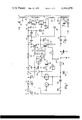
- FIG. 1 illustrates an electric diagram of a horizontal deflection and auxialiary circuit supply circuit for a monochromatic 24" 110° screen television receiver embodying the circuit of the present invention
- FIG. 2 illustrates a few waveforms to show how the circuit of FIG. 1 operates
- FIG. 3 shows a variation of part of the circuit shown in FIG. 1;
- FIG. 4 illustrates in detail a part of the circuits shown in FIGS. 1 and 3;
- FIG. 5 shows a different embodiment of a part of the diagram of FIG. 1, comprising the circuit of the present invention.
- FIG. 6 shows a variation of part of the circuit shown in FIG. 5.
- letters D and D' indicate two input terminals of a horizontal deflection and auxiliary circuit supply circuit for a 24" 110° screen monochrome television set.
- a 220 V - 50 Hz nominal supply voltage (domestic mains voltage) is connected to said terminals D and D'.
- Terminal D' is connected to ground; terminal D is connected to a conventional voltage rectifying and levelling circuit consisting of resistors 11 and 12, diode 13 and condensers 14, 15, 16 and 17.
- resistor 11 is connected between the terminal D and the anode of the diode 13, parallel to which there is connected the condenser 14.
- the cathode of the diode 13 is connected, to ground, both through condenser 15 and through the series of the resistor 12 and the condensers 16 and 17.
- a d.c. average voltage of roughly 250 V, under nominal conditions, is thus available at point F, that is, at the connection in series between resistor 12 and condenser 16.
- Point F is connected, through an inductor 18, to the collector of a NPN transistor 19 (final line transistor).
- the collector of this transistor 19 is connected to one end G of a primary winding 21 of an extra-high-voltage (EHV) transformer 22 having a number of secondary windings, by means of a network composed of diodes 24 and 25, condenser 26 and component Z, which will be described later in more detail.
- EHV extra-high-voltage
- Diode 24 is connected by the anode to the end G of the primary winding 21 and by the cathode to the collector of the transistor 19; diode 25 is connected by the cathode to the anode of the diode 24 and by the anode to the condenser 26 which, at the other end, is connected to the collector of the transistor 19; finally, component Z is connected parallel to diode 25.
- the other end of the primary winding 21 of the transformer 22 is connected to ground through a condenser 28 and parallel to said winding 21 is connected the circuit of the horizontal deflection yoke through which has to flow the saw-current, and which is formed by the series of two deflection coils 30 connected parallel (resultant inductance 2 mH), a variable linearity coil 31 (dampened) in parallel to a resistor 32, and a series condenser 33 (for tangent correction).
- a parallel condenser 34 Connected between end G of the primary winding 21 and ground is a parallel condenser 34 for the retrace interval time, and parallel to it is connected also a parallel recovery diode 35 having its anode connected to ground.
- Transformer 22 has three secondary windings, namely:
- a second secondary winding 38 for biasing the base of the final transistor 19 (through a diode 39 and a resistor 40); namely, one end of the winding 38, connected parallel to which is a condenser 41, is connected to the anode of the diode 39, whose cathode is connected, through resistor 40, to the base of the transistor 19.
- the cathode of diode 39 is connected, through a resistor 42, to the collector of a NPN transistor 43 whose emitter is grounded, and the other end of the winding 38 is connected to the emitter of a NPN transistor 44 which, in its turn, is grounded through a resistor 45;
- a third secondary winding 46 for providing low d.c. voltages at points A and C for supplying other circuits on the television set; namely, the winding 46 is connected between the ground and the anode of a diode 47, parallel to which is connected a condenser 48, and whose cathode leads to point C.
- An intermediate tap of the winding 46 leads to the anode of a diode 50, connected parallel to which is a condenser 51 and whose cathode leads to point A.
- a condenser 52 Connected between point A and ground is a condenser 52.
- Point A is also connected to one end of a resistor 54 whose other end is connected to the cathode of a Zener diode 55 whose anode is grounded, and to the supply source of two known circuits indicated by letters O and MC and shown in block form, and which represent, respectively, the horizontal oscillator O (which receives the synchronizing signals at an input S) and the control module MC which receives the output of oscillator O and sends to the final line transistor 19, through pilot transistors 43 and 44, a control signal which varies in duration according to the voltage values picked up from point F (through a resistor 60) and from the emitter of the transistor 44 (through a resistor 61 connected to an adjustable resistor 62 and to ground through a resistor 63) and which it receives at an input Q from one end of the resistor 60 and from one end of the adjustable resistor 62.
- control module MC is a pulse width control circuit between the horizontal oscillator and horizontal deflection driver stage and, as such, supplies width-modulated drive pulses to the driver stage varying in length inversely with respect to amplitude changes in the supply voltage at point F and the emitter voltage of transistor 44.
- Pulse width control circuits suitable for use as control module MC are well known in the art and may be, for example, of the type shown as an oscillator modulator driver in FIGS.
- a starter circuit is provided to start the circuit as soon as it is turned on; it supplies the voltage generated at the terminals of condenser 17, at one end, to the base of final transistor 19 (point P) through a resistor 67 and, at the other end, to the O and Mc circuits through a resistor 68 and a diode 69 connected in series.
- FIG. 3 shows diagrammatically a possible variation to the circuit shown in FIG. 1; as can be seen from this FIG. 3, the network composed of diodes 24 and 25, condenser 26 and component Z has been moved over from the hot side of the deflection circuit to the ground side.
- said network is no more connected between the collector of transistor 19 and the deflection circuit comprising coil 30, condensers 33 and 34 and diode 35, such a circuit being directly connected to the collector of transistor 19, whilst said network is connected to ground.
- FIG. 4 shows in detail the component Z, which is connected parallel to diode 25 both in the circuit shown in FIG. 1 and in the circuit shown in FIG. 3.
- a condenser 81 connected parallel to a load 82 which may be a d.c. accessory load, for example the vertical deflection circuit or the audio circuit, or even the heater of the kinescope or the filament of illumination lamps.
- FIG. 5 shows a diagram which comprises the circuit of the present invention, and which imitates, in many, even not shown parts, the diagram shown in FIG. 1.
- a d.c. voltage which, let us suppose, for the sake of simplicity, is + 275 V ⁇ 20% (+ 330 V and +220 V when the active mains voltage is 264 V and 176 V respectively).
- this positive d.c. voltage supplies the collector of the transistor 19, which can cut off under inductive load a peak current of 2.5 A and withstand a maximum crest voltage on the collector of 1500 volts.
- the said transistor 19 has its emitter connected to ground, and to terminal P, connected to its base, there are applied control pulses of suitable shape and amplitude (according to the transistor maker's instructions) with a repetition frequency equal to the line frequency of the television signal (15625 Hz in Europe, equivalent to 64 microseconds for a complete line scanning cycle).
- the length of the said control pulses applied to terminal P can be varied and is controlled, in the known manner, by a control circuit (not shown in FIG. 5 and similar to the corresponding circuit of FIG. 1) which is sensitive to the supply voltage at terminal F and varies the length of the pulses applied to the base of the transistor 19 accordingly (that is, the length of the interval during which the transistor 19 is conductive) in the sense that pulse length increases when supply voltage falls.
- a control circuit (not shown in FIG. 5 and similar to the corresponding circuit of FIG. 1) which is sensitive to the supply voltage at terminal F and varies the length of the pulses applied to the base of the transistor 19 accordingly (that is, the length of the interval during which the transistor 19 is conductive) in the sense that pulse length increases when supply voltage falls.
- pulse length is varied from a minimum of 29 microseconds (corresponding to a r.m.s. mains voltage of 264 V) to a minimum of 44 microseconds (corresponding to a r.m.s. mains voltage of 176 V).
- the energy ⁇ stored in inductor 18' (having the value L 1 ) at the end of a period ⁇ of application of a voltage V can be calculated using the following equation: ##EQU1## So, it can be seen that in order that the energy stored in inductor 18' remains constant, the product V ⁇ must also be constant.
- the collector of the transistor 19 is connected to the deflection circuit (consisting of the parallel formed by deflection coil 30 connected in series to condenser 33, retrace interval condenser 34' similar to condenser 34, and parallel recovery diode 35) over a network consisting of diodes 24 and 25 and condenser 26' similar to condenser 26 of FIG. 1.
- a coupling condenser 28' similar to condenser 28 is the primary winding 21 of the transformer 22.
- the said transformer besides having the winding 36 for the EHV to which there is connected the diode 37 and which supplies point E with a d.c. voltage of about 18 KV (in the absence of load), is also provided with a low-voltage secondary winding 101, to one end of which there is connected the anode of a diode 102, whilst a filter condenser 103 is connected between the cathode of the diode 102 and the other end of the winding 101.
- a d.c. positive voltage of + 25 V for supplying the circuits of the tuner, the FI amplifier in the television set, the sync signal separator as well as the line and frame collectors.
- the total current absorption at point W is roughly 200 mA.
- a component Z' Connected between the anode of the diode 25 and ground is a component Z', similar to component Z.
- the said component Z' comprises a diode 110 whose cathode is connected to the anode of the diode 25 and whose anode is connected to the anode of a diode 111 having its cathode connected to ground, and to one end of an inductor 112.
- the other end of the inductor 112 is connected to ground through an inductor 113 and a condenser 114 connected in series, and to the cathode of a diode 115 whose anode is connected to ground through a condenser 116.
- the retrace interval starts the instant transistor 19 is blocked (disabled) by the control pulse: with the passage through diode 24 and a transistor 19 cut off, the current from coil 30 flows into condenser 34' charging it to a maximum of roughly 800 positive V. (Coil 30 is 2 mH, peak-peak deflection current roughly 2.7A and condenser 34' 4.3 nF).
- inductor 18' the current which was circulating in inductor 18' also finds the passage through transistor 19 cut off and also flows into condenser 34' through condenser 26' and diode 25. This energy coming from inductor 18' is used partly to compensate deflection circuit losses (and losses in the circuits and loads connected to it, points W and E) and partly to charge condenser 26'.
- Condenser 26' in fact, remains charged at the end of the retrace interval until transistor 19 becomes once more conductive, as time constant defined by inductor 18' (L 1 ) and condenser 26' (C 1 ) is sufficiently great with respect to the non-conductive period of transistor 19.
- the instant transistor 19 becomes conductive, condenser 26' discharges rapidly through transistor 19 at one end and the circuit comprising diode 110, inductor 112, diode 115 with condenser 116 and inductor 113 with condenser 114 at the other.
- Condensers 114 and 116 are much greater than condenser 26' so that the power of condenser 26' charges inductors 112 and 113 and, instead of returning through diode 110, discharges in condensers 114 and 116 through diodes 111 and 115, this being the easiest way, during the remainder of the cycle.
- transformer 22 results less overworked than if it was also called upon to transform the power required to supply the vertical deflection and audio stages.
- Total mains consumption of the whole set has been measured at only 47 W.
- Maximum current in transistor 19, at the end of scan, is 1.75 A, and no sharp increases in voltage occur when transistor 19 is cut off.
- the circuit would have been simplier; by simply removing diode 115 and condenser 116 from FIG. 5 and short-circuiting the inductor 112, all the available power could be picked up at point T.
- the circuit behaves more or less in the same way as a constant-power generator so that by varying load impedance the voltage at the terminals is also varied.
- diode 111 can be removed; in this case, the current flowing in inductor 112 and/or 113 flows into condenser 116 and/or 114 through diodes 110, 25, 24 and transistor 19 but is cut off the instant transistor 19 is disabled; the remaining available power is then sent back to the supply. However, this increases the maximum current in transistor 19.
- the extra power can be dissipated in a resistor, as shown by the variation in FIG. 6, in which the component Z' is replaced by a component Z" which comprises, connected in series to ground, the diode 110, a resistor 120, the inductor 112 and the condenser 114.
- a voltage of -13 V and a current of 320 mA, that is, roughly 4W, is picked up at point T between the inductor 112 and the condenser 114, in the same way as from point T in FIG. 5, and to prevent increasing the current in transistor 19 the remaining power is dissipated in resistor 120. In this way, the current in inductor 112 falls to almost a negligible level before transistor 19 is disabled.
- FIG. 2 shows, not to scale, in successive lines:
- the saw-tooth deflection current flows in coil 30 at increasing value ranging from zero to a maximum and flows, through coil 31, condenser 33 and condenser 28, in diode 24 and transistor 19 (as well as in condenser 73 between the emitter of transistor 19 and ground); the rise in current is shown in the second and third curve in FIG 2; the waveform superposed on the saw-tooth current comes from the extra-high-voltage secondary winding 36.
- transistor 19 is disabled by the control pulse; therefore, currents I 19 and I 24 are cut off; the retrace interval starts; the deflection current flows to charge condenser 34, which is then discharged again onto coils 30; at the same time, the energy stored in coil 18 flows through condenser 26 and diode 25 to assist in charging condenser 34 and put back into the deflection circuit the energy consumed as a result of passive losses and loads connected to it (supplies A, C and E).
- the transistor 19 is made conductive by the control pulse and condenser 26 discharges through transistor 19, diode 35 and component Z.
- the current in component Z gives rise, through inductor 80 and condenser 81 which effect a filtering action, to a levelled low voltage for supplying the load 82.
- this load 82 may comprise a resistor to dissipate part of the energy. This brings us back to instant t 3 , and the cycle ends.
- the voltage between the collector of transistor 19 and the ground is grater than that at the terminals of condenser 34, during the interval in which transistor 19 is disabled (instants t o -t 3 ). Consequently, the average value of the first voltage, which is the value of the supply voltage (point F), is greater than the average value of the second voltage.
- the average value of the first voltage is roughly 250 V while the average value of the second voltage is roughly 130 V.
- the circuit shown in FIG. 1 provides a picture of more or less constant amplitude on the television screen with mains voltage between 170 and 260 V (r.m.s.) and beam current variable between zero and 400 ⁇ A.
- the voltage which develops on the collector of the transistor 19 the instant it is disabled has practically the same variation speed (dV/dt) as the voltage which develops at the terminals of the condenser 34, owing to the fact that the collector of transistor 19 is connected to the insulated armature of condenser 34 (which is discharged at t o ) through condenser 26 (which has more than twice the capacity of condenser 34) and diode 25 and that at the instant t o condenser 26 is substantially discharged or charged with very low voltage.
Landscapes
- Details Of Television Scanning (AREA)
- Video Image Reproduction Devices For Color Tv Systems (AREA)
Applications Claiming Priority (4)
| Application Number | Priority Date | Filing Date | Title |
|---|---|---|---|
| IT69438A/76 | 1976-10-11 | ||
| IT6943776A IT1071508B (it) | 1976-10-11 | 1976-10-11 | Circuito per ottenere una corrente a denti di sega in una bobina |
| IT6943876A IT1071509B (it) | 1976-10-11 | 1976-10-11 | Circuito per ottenere una corrente a denti di sega in una bobina e per alimentare almeno un circuito ausiliario |
| IT69437A/76 | 1976-10-11 |
Publications (1)
| Publication Number | Publication Date |
|---|---|
| US4144479A true US4144479A (en) | 1979-03-13 |
Family
ID=26329956
Family Applications (1)
| Application Number | Title | Priority Date | Filing Date |
|---|---|---|---|
| US05/835,375 Expired - Lifetime US4144479A (en) | 1976-10-11 | 1977-09-21 | Circuit for providing saw-tooth current in a coil |
Country Status (5)
| Country | Link |
|---|---|
| US (1) | US4144479A (Direct) |
| DE (1) | DE2745417C2 (Direct) |
| FR (1) | FR2367381A1 (Direct) |
| GB (1) | GB1555178A (Direct) |
| NL (1) | NL7711110A (Direct) |
Cited By (4)
| Publication number | Priority date | Publication date | Assignee | Title |
|---|---|---|---|---|
| US4665347A (en) * | 1983-07-22 | 1987-05-12 | International Standard Electric Corporation | Circuit for producing the operating voltages and the horizontal-deflection current for picture-reproducing equipment |
| US4686431A (en) * | 1984-10-19 | 1987-08-11 | U.S. Philips Corporation | Line output circuit for generating a line frequency sawtooth current |
| US4707640A (en) * | 1984-11-09 | 1987-11-17 | Hitachi, Ltd. | Horizontal deflection output circuit |
| US4780648A (en) * | 1986-11-04 | 1988-10-25 | Rca Licensing Corporation | Deflection apparatus |
Families Citing this family (1)
| Publication number | Priority date | Publication date | Assignee | Title |
|---|---|---|---|---|
| IT1108039B (it) * | 1978-06-08 | 1985-12-02 | Indesit | Circuito per ottenere una corrente a denti di sega in una bobina |
Citations (2)
| Publication number | Priority date | Publication date | Assignee | Title |
|---|---|---|---|---|
| US3906307A (en) * | 1972-12-19 | 1975-09-16 | Philips Corp | Circuit arrangement for producing a sawtooth current through a line deflection coil in an image display apparatus |
| GB1466151A (en) * | 1973-03-21 | 1977-03-02 | Philips Electronic Associated | Line deflection circuit for cahtode-ray tubes |
Family Cites Families (1)
| Publication number | Priority date | Publication date | Assignee | Title |
|---|---|---|---|---|
| DE2208259C3 (de) * | 1972-02-22 | 1983-12-15 | Adam, Martin, 4628 Lünen | Mit einer einen Luftstrom erzeugenden Vorrichtung zusammenwirkende Lüftungsjalousie |
-
1977
- 1977-09-20 GB GB39127/77A patent/GB1555178A/en not_active Expired
- 1977-09-21 US US05/835,375 patent/US4144479A/en not_active Expired - Lifetime
- 1977-10-08 DE DE2745417A patent/DE2745417C2/de not_active Expired
- 1977-10-10 NL NL7711110A patent/NL7711110A/xx not_active Application Discontinuation
- 1977-10-11 FR FR7730510A patent/FR2367381A1/fr active Granted
Patent Citations (2)
| Publication number | Priority date | Publication date | Assignee | Title |
|---|---|---|---|---|
| US3906307A (en) * | 1972-12-19 | 1975-09-16 | Philips Corp | Circuit arrangement for producing a sawtooth current through a line deflection coil in an image display apparatus |
| GB1466151A (en) * | 1973-03-21 | 1977-03-02 | Philips Electronic Associated | Line deflection circuit for cahtode-ray tubes |
Cited By (4)
| Publication number | Priority date | Publication date | Assignee | Title |
|---|---|---|---|---|
| US4665347A (en) * | 1983-07-22 | 1987-05-12 | International Standard Electric Corporation | Circuit for producing the operating voltages and the horizontal-deflection current for picture-reproducing equipment |
| US4686431A (en) * | 1984-10-19 | 1987-08-11 | U.S. Philips Corporation | Line output circuit for generating a line frequency sawtooth current |
| US4707640A (en) * | 1984-11-09 | 1987-11-17 | Hitachi, Ltd. | Horizontal deflection output circuit |
| US4780648A (en) * | 1986-11-04 | 1988-10-25 | Rca Licensing Corporation | Deflection apparatus |
Also Published As
| Publication number | Publication date |
|---|---|
| DE2745417C2 (de) | 1987-01-29 |
| FR2367381B1 (Direct) | 1983-11-04 |
| FR2367381A1 (fr) | 1978-05-05 |
| DE2745417A1 (de) | 1978-04-13 |
| NL7711110A (nl) | 1978-04-13 |
| GB1555178A (en) | 1979-11-07 |
Similar Documents
| Publication | Publication Date | Title |
|---|---|---|
| US3828239A (en) | High dc voltage generating circuit | |
| US2536857A (en) | High-efficiency cathode-ray deflection system | |
| US4329729A (en) | Side pincushion modulator circuit with overstress protection | |
| US4079294A (en) | Control circuit arrangement for generating a control signal for a voltage converter | |
| US4385263A (en) | Television receiver, push-pull inverter, ferroresonant transformer power supply synchronized with horizontal deflection | |
| US5331532A (en) | High voltage regulating circuit | |
| KR920005869B1 (ko) | 동-서 핀쿳션 보정 수평편향회로 | |
| US4177393A (en) | Drive circuit for a television deflection output transistor | |
| US4027200A (en) | High voltage generating circuit | |
| US3689797A (en) | Circuit arrangement in a picture display device utilizing a stabilized supply voltage circuit | |
| US4144479A (en) | Circuit for providing saw-tooth current in a coil | |
| US3956713A (en) | Astable multivibrator having adjustable pulse width at constant frequency | |
| GB2041668A (en) | Ferroresonant stabiliser for TV | |
| US6072709A (en) | Multiple output voltage converter with improved cross-regulation | |
| US4484113A (en) | Regulated deflection circuit | |
| US4041355A (en) | High voltage generating circuit | |
| US4464612A (en) | Circuit arrangement for a picture display device for generating a sawtooth-shaped line deflection current | |
| US4634938A (en) | Linearity corrected deflection circuit | |
| US4472662A (en) | Deflection circuit | |
| FI70104B (fi) | Reglerad linjeavlaenkningsapparat | |
| KR100239076B1 (ko) | Crt 전극 전원용 전압 부우스터 | |
| US4024434A (en) | Circuit arrangement in a television receiver provided with a line deflection circuit and a switched supply voltage circuit | |
| US4362974A (en) | Commutated switched regulator with line isolation for transistor deflection | |
| EP0370660B1 (en) | Power supply protection circuit | |
| US5142206A (en) | Slow turn-on in a deflection circuit |
Legal Events
| Date | Code | Title | Description |
|---|---|---|---|
| AS | Assignment |
Owner name: SISVEL S.P.A., ROME, VIA 4 FONTANE NO. 20 Free format text: ASSIGNMENT OF ASSIGNORS INTEREST.;ASSIGNOR:INDESIT INDUSTRIA ELETTRODOMESTICI ITALIANA S.P.A.;REEL/FRAME:005610/0884 Effective date: 19850731 |
|
| AS | Assignment |
Owner name: SKEPSY S.A., LUXEMBOURG Free format text: ASSIGNMENT OF ASSIGNORS INTEREST;ASSIGNORS:S.I.SV.EL. S.P.A.;EDICO S.R.L.;REEL/FRAME:007185/0877 Effective date: 19940907 |
|
| STCF | Information on status: patent grant |
Free format text: PATENTED FILE - (OLD CASE ADDED FOR FILE TRACKING PURPOSES) |