US4130920A - Machine tool - Google Patents
Machine tool Download PDFInfo
- Publication number
- US4130920A US4130920A US05/843,769 US84376977A US4130920A US 4130920 A US4130920 A US 4130920A US 84376977 A US84376977 A US 84376977A US 4130920 A US4130920 A US 4130920A
- Authority
- US
- United States
- Prior art keywords
- gear
- pallet
- pallets
- work stations
- machine tool
- Prior art date
- Legal status (The legal status is an assumption and is not a legal conclusion. Google has not performed a legal analysis and makes no representation as to the accuracy of the status listed.)
- Expired - Lifetime
Links
Images


Classifications
-
- B—PERFORMING OPERATIONS; TRANSPORTING
- B23—MACHINE TOOLS; METAL-WORKING NOT OTHERWISE PROVIDED FOR
- B23Q—DETAILS, COMPONENTS, OR ACCESSORIES FOR MACHINE TOOLS, e.g. ARRANGEMENTS FOR COPYING OR CONTROLLING; MACHINE TOOLS IN GENERAL CHARACTERISED BY THE CONSTRUCTION OF PARTICULAR DETAILS OR COMPONENTS; COMBINATIONS OR ASSOCIATIONS OF METAL-WORKING MACHINES, NOT DIRECTED TO A PARTICULAR RESULT
- B23Q5/00—Driving or feeding mechanisms; Control arrangements therefor
- B23Q5/22—Feeding members carrying tools or work
- B23Q5/34—Feeding other members supporting tools or work, e.g. saddles, tool-slides, through mechanical transmission
- B23Q5/38—Feeding other members supporting tools or work, e.g. saddles, tool-slides, through mechanical transmission feeding continuously
- B23Q5/385—Feeding other members supporting tools or work, e.g. saddles, tool-slides, through mechanical transmission feeding continuously using a gear and rack mechanism or a friction wheel co-operating with a rail
-
- B—PERFORMING OPERATIONS; TRANSPORTING
- B23—MACHINE TOOLS; METAL-WORKING NOT OTHERWISE PROVIDED FOR
- B23Q—DETAILS, COMPONENTS, OR ACCESSORIES FOR MACHINE TOOLS, e.g. ARRANGEMENTS FOR COPYING OR CONTROLLING; MACHINE TOOLS IN GENERAL CHARACTERISED BY THE CONSTRUCTION OF PARTICULAR DETAILS OR COMPONENTS; COMBINATIONS OR ASSOCIATIONS OF METAL-WORKING MACHINES, NOT DIRECTED TO A PARTICULAR RESULT
- B23Q1/00—Members which are comprised in the general build-up of a form of machine, particularly relatively large fixed members
- B23Q1/25—Movable or adjustable work or tool supports
- B23Q1/44—Movable or adjustable work or tool supports using particular mechanisms
- B23Q1/50—Movable or adjustable work or tool supports using particular mechanisms with rotating pairs only, the rotating pairs being the first two elements of the mechanism
- B23Q1/52—Movable or adjustable work or tool supports using particular mechanisms with rotating pairs only, the rotating pairs being the first two elements of the mechanism a single rotating pair
- B23Q1/522—Movable or adjustable work or tool supports using particular mechanisms with rotating pairs only, the rotating pairs being the first two elements of the mechanism a single rotating pair which is perpendicular to the working surface
-
- B—PERFORMING OPERATIONS; TRANSPORTING
- B23—MACHINE TOOLS; METAL-WORKING NOT OTHERWISE PROVIDED FOR
- B23Q—DETAILS, COMPONENTS, OR ACCESSORIES FOR MACHINE TOOLS, e.g. ARRANGEMENTS FOR COPYING OR CONTROLLING; MACHINE TOOLS IN GENERAL CHARACTERISED BY THE CONSTRUCTION OF PARTICULAR DETAILS OR COMPONENTS; COMBINATIONS OR ASSOCIATIONS OF METAL-WORKING MACHINES, NOT DIRECTED TO A PARTICULAR RESULT
- B23Q16/00—Equipment for precise positioning of tool or work into particular locations not otherwise provided for
- B23Q16/02—Indexing equipment
- B23Q16/04—Indexing equipment having intermediate members, e.g. pawls, for locking the relatively movable parts in the indexed position
-
- B—PERFORMING OPERATIONS; TRANSPORTING
- B23—MACHINE TOOLS; METAL-WORKING NOT OTHERWISE PROVIDED FOR
- B23Q—DETAILS, COMPONENTS, OR ACCESSORIES FOR MACHINE TOOLS, e.g. ARRANGEMENTS FOR COPYING OR CONTROLLING; MACHINE TOOLS IN GENERAL CHARACTERISED BY THE CONSTRUCTION OF PARTICULAR DETAILS OR COMPONENTS; COMBINATIONS OR ASSOCIATIONS OF METAL-WORKING MACHINES, NOT DIRECTED TO A PARTICULAR RESULT
- B23Q16/00—Equipment for precise positioning of tool or work into particular locations not otherwise provided for
- B23Q16/02—Indexing equipment
- B23Q16/08—Indexing equipment having means for clamping the relatively movable parts together in the indexed position
-
- B—PERFORMING OPERATIONS; TRANSPORTING
- B23—MACHINE TOOLS; METAL-WORKING NOT OTHERWISE PROVIDED FOR
- B23Q—DETAILS, COMPONENTS, OR ACCESSORIES FOR MACHINE TOOLS, e.g. ARRANGEMENTS FOR COPYING OR CONTROLLING; MACHINE TOOLS IN GENERAL CHARACTERISED BY THE CONSTRUCTION OF PARTICULAR DETAILS OR COMPONENTS; COMBINATIONS OR ASSOCIATIONS OF METAL-WORKING MACHINES, NOT DIRECTED TO A PARTICULAR RESULT
- B23Q39/00—Metal-working machines incorporating a plurality of sub-assemblies, each capable of performing a metal-working operation
- B23Q39/04—Metal-working machines incorporating a plurality of sub-assemblies, each capable of performing a metal-working operation the sub-assemblies being arranged to operate simultaneously at different stations, e.g. with an annular work-table moved in steps
- B23Q39/042—Metal-working machines incorporating a plurality of sub-assemblies, each capable of performing a metal-working operation the sub-assemblies being arranged to operate simultaneously at different stations, e.g. with an annular work-table moved in steps with circular arrangement of the sub-assemblies
-
- B—PERFORMING OPERATIONS; TRANSPORTING
- B23—MACHINE TOOLS; METAL-WORKING NOT OTHERWISE PROVIDED FOR
- B23Q—DETAILS, COMPONENTS, OR ACCESSORIES FOR MACHINE TOOLS, e.g. ARRANGEMENTS FOR COPYING OR CONTROLLING; MACHINE TOOLS IN GENERAL CHARACTERISED BY THE CONSTRUCTION OF PARTICULAR DETAILS OR COMPONENTS; COMBINATIONS OR ASSOCIATIONS OF METAL-WORKING MACHINES, NOT DIRECTED TO A PARTICULAR RESULT
- B23Q7/00—Arrangements for handling work specially combined with or arranged in, or specially adapted for use in connection with, machine tools, e.g. for conveying, loading, positioning, discharging, sorting
- B23Q7/03—Arrangements for handling work specially combined with or arranged in, or specially adapted for use in connection with, machine tools, e.g. for conveying, loading, positioning, discharging, sorting by means of endless chain conveyors
- B23Q7/035—Arrangements for handling work specially combined with or arranged in, or specially adapted for use in connection with, machine tools, e.g. for conveying, loading, positioning, discharging, sorting by means of endless chain conveyors on which work holders are fixed
-
- Y—GENERAL TAGGING OF NEW TECHNOLOGICAL DEVELOPMENTS; GENERAL TAGGING OF CROSS-SECTIONAL TECHNOLOGIES SPANNING OVER SEVERAL SECTIONS OF THE IPC; TECHNICAL SUBJECTS COVERED BY FORMER USPC CROSS-REFERENCE ART COLLECTIONS [XRACs] AND DIGESTS
- Y10—TECHNICAL SUBJECTS COVERED BY FORMER USPC
- Y10T—TECHNICAL SUBJECTS COVERED BY FORMER US CLASSIFICATION
- Y10T29/00—Metal working
- Y10T29/51—Plural diverse manufacturing apparatus including means for metal shaping or assembling
- Y10T29/5124—Plural diverse manufacturing apparatus including means for metal shaping or assembling with means to feed work intermittently from one tool station to another
- Y10T29/5127—Blank turret
Definitions
- the present invention constitutes a specific, needed improvement over the machine tool disclosed in U.S. Pat. No. 3,609,838, also constitutes a specific variant upon the machine tool design of my earlier application Ser. No. 801,181.
- the pallet was connected to the gear through a simple "lost motion" connection, and the pallet could move relative to the gear as the pallet was being transported by the gear between machining locations.
- the gear is elevated for transport and is lowered for clamping at the machine location.
- a plurality of hydraulically actuated rollers contact the undersurface of the gear and support the gear for rotation when the rollers are elevated.
- the gear is supported upon the fixed composite support table with each gear-carried pallet in rough alignment with a machining location.
- Hydraulic clamping means preferably commonly actuated with the gear raising and lowering rollers, is provided to firmly clamp the locating surfaces in interfitting engagement.
- a spring urged shot pin interconnects the pallet and the gear during transport, thereby fixing the workpieces to the gear during movement.
- the spring force is removed from the locating pin, so that the pallet can be freely adjusted relative to the gear.
- Yet another, and no less important, object of the present invention is the provision of a machine tool wherein an annular gear carries a series of pallets between a corresponding series of work stations and a common fluid pressure actuated mechanism is provided for raising and lowering the gear and for accurately locating and clamping each pallet in an accurate machining location.
- FIG. 1 is a plan view, on a reduced scale, of a machine tool of the present invention
- FIG. 2 is an enlarged fragmentary plan view
- FIG. 3 is a fragmentary side elevational view of the machine tool of the present invention.
- FIG. 4 is a fragmentary sectional view taken along the planes 4--4 of FIG. 2 illustrating the machine tool in its operative machining position;
- FIG. 5 is a sectional view similar to FIG. 4 showing the machine tool in its elevated, transport position
- FIG. 6 is a view similar to FIG. 3, but on a reduced scale of a modified version of the machine tool of the present invention
- FIG. 7 is a sectional view taken along the plan 7--7 of FIG. 6;
- FIGS. 8 and 9 are enlarged fragmentary elevational views of the locating and clamping mechanism of that embodiment of the machine shown in FIGS. 6 and 7.
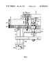
- FIGS. 1-5 A first preferred embodiment of the present invention is illustrated in FIGS. 1-5, inclusive and, as best illustrated in FIG. 1, this version of the invention incorporates a composite base or support table 10 comprising segmental base sections 11 positioned between peripherally spaced work stations 12 traversed by an annular gear 15 carrying pallets 16.
- this version of the invention shown in FIG. 1 there are four work stations 12, four pallets 16, and four support segments 11 spanning the work stations. It will be appreciated that the number of work stations may vary from 2 to 8 or more, with one or more of these work stations being loading and unloading stations, and that the machine normally incorporates a number of pallets 16 equivalent to the number of work stations 12.
- each work station includes an upper planar support or reference surface 17 formed as a part of support 18 mounted on legs 19 and forming a part of the composite work support or work table 10.
- the surfaces 17 form reference surfaces from which are mounted the machine tools which carry out various machine operations on workpieces carried by the pallets 16. For clarity of illustration, neither the machine tools nor the workpieces are shown, since these elements are widely variable and form no portion of the present invention.
- the annular gear 15 is provided with outwardly facing, lower peripheral geared teeth 20 and with an upstanding annular support flange 21.
- the gear is supported for rotation upon internal guide rollers and is driven by a powered pinion gear, all as disclosed in my earlier application Ser. No. 801,181, so that these elements are not herein shown in the drawings.
- the gear 15 carries on its upper surface a pair of mounting flanges 23 fixedly secured to the upper edge of the gear flange 21 by suitable means (not shown), these mounting brackets 23 being generally "T"-shaped as shown in elevation in FIG. 2.
- brackets 23 serve to support the pallets 16 for travel with the gear 15, each bracket having a pair of depending tubular bushings 25 through which a support pin 26 projects.
- Each pin is provided with a lower enlarged end 27, and a compression spring 28 is confined between the bracket 23 and the pin head 27.
- the upper end of each pin 26 is provided with a conical locating head 30 entrapped within a locating assembly 32 carried by the pallet 16.
- Each locating assembly 32 includes a lower locating block 33 seated in a recess 34 formed in the upper surface of the pallet, and, each block 33 is confined in the recess 34 by an upper closure plate 35 secured to the pallet by suitable means 36.
- Each block 33 has an upwardly flaring conical recess 37 mating with the conical head 30 of the pin 26.
- the pin head 27 of the pin 26 contacts the upper surface of a fixed abutment block 38 which is secured to the table reference surface 17.
- the head of the block 38 is located so that lowering of the gear 15 abuts the head 27 with the block 38 to compress the spring 28, thereby spacing the conical head 30 of the pin 26 from the conical locating seat 37 and freeing the pallet 16 for movement relative to the gear 15.
- the gear 15 is in its elevated transport position, as illustrated in FIG. 5, the head 27 is elevated from contact with the block 38, the spring 28 lowers the pin 26 and the surfaces 30, 37 are urged into contact under the force of the spring 28, thereby fixing the pallet 16 to the gear 15 for comovement.
- each work station includes a pair of power actuators or means 40.
- the power actuators 40 are hydraulic cylinders, although pneumatic cylinders or electrical actuators, such as recirculating ball screws can be utilized.
- a piston rod 41 of each of the cylinders 40 projects upwardly and carries at its upper end a support roller or element 42 mounted on a horizontal axle 43.
- the rollers or support elements or rotatable means 42 are vertically aligned with the undersurface of the gear 15 for contact with the gear upon vertical upward actuation of the actuators 40.
- the two cylinders for each work station are simultaneously actuated and are interconnected by a cross bar 45 which project through vertically elongated apertures 46 in the support table legs 19.
- a cross bar 45 Secured to the bar 45 and projecting upwardly therefrom are vertical actuating rods 47 bearing at their upper ends enlarged clamping heads 48.
- the rods 47 are guided by annular sleeves 49 carried by locating embossments indicated generally at 50, 51.
- These locating embossments 50, 51 have lower cylindrical extensions 52 located in apertures 53 in the table plate 18 and have upper enlarged ends 54.
- Embossments 50 are provided at their upper extremities with conical locating surfaces 55, while the embossments 51 are provided at their upper extremities with planar surfaces 56 for a purpose to be hereafter more fully described.
- Each machining location is provided with a pair of locating embossments 50 and a pair of locating embossments 51, the embossments 50 being located diagonally with respect to one another, and the embossments 51 occupying the other diagonal.
- each of the pallets 16 Formed on the undersurface of each of the pallets 16 are a plurality of depending bosses 60 to which are secured, as by cap screws 61, a generally cylindrical depending locating element 62, 63. Four of these depending elements 62, 63 are provided for vertical alignment with the four locating embossments 50, 51.
- the locating elements 62, 63 are each provided with intermediate slots 64 accommodating the entry of the enlarged clamping head 48 as the gear and the pallet are rotated with respect to the support 18 and the heads 48.
- the locating elements 62, 63 are provided with lower abutting faces 65, 66 for contacting the upper extremities 55, 56 of the locating embossments 50, 51.
- the lower surface 65 of the locating element 62 is contoured to match the conical surface 55, i.e. the surface 65 is in the form of a concave conical surface matingly receiving the convex conical surface 55.
- the lower extreme surface 66 of the locating element 63 is planar to matchingly engage the planar surface 56 of the locating embossment 51.
- the first step in indexing the table is to actuate the power actuators 40 to raise the rollers 42 into contact with the undersurface of the gear 15, and then to further actuate the actuators 40 to elevate the gear 15 from contact with the surface 17 of the support table 18. It will be seen that this elevation of the gear 15 will simultaneously elevate the cross member 45 and raise the clamping heads 48 to their positions illustrated in FIG. 5, so that the pallet 16 is no longer clamped to the support 18.
- the gear 15 is indexed to the next machining station (by means shown and described in my earlier application). This movement is accommodated by the slots 64 in the depending clamping bosses 62,63 of the pallets 16, which slots allow relative movement between the elevated clamping heads 48 and the embossments 50, 51.
- the actuators 40 are actuated to lower the gear 15 and the pallets 16 carried thereby.
- Lowering of the pallets 16 brings the enlarged pin heads 27 into contact with the underlying abutments 38, separating the conical pinhead 30 from its seating surface 37 and freeing the pallet 16 for adjustment relative to the gear 15.
- the bottom surfaces 65, 66 contact their corresponding surfaces 55, 56 with the mating conical surfaces 55, 65 accurately locating the pallet 16 relative to the table reference surface 17 and the machining elements carried thereby.
- continued downward actuation of the actuators 40 bring the enlarged heads 48 (which were positioned in the slots 64 during gear rotation to the next machining operation) downwardly into clamping engagement when the locating elements 62,63 to finally clamp the pallet 16 in position.
- FIGS. 6 through 9 A different embodiment of the present invention is illustrated in FIGS. 6 through 9.
- the pallet 16 and the support 18 engage one another through plane abutment surfaces 51, 63, provided with the same elevating and lowering mechanism as earlier described in connection with FIGS. 1 through 5. It will be noted that three such abutment surfaces 51, 63 are provided.
- Located at the machining station are a plurality of upstanding abutments 80, 81 and 82. Each of these abutments is provided with a planar upper surface 83 and an upwardly projecting tapered key 84.
- the keys 84 for the abutments 80 and 81 are oriented to lie tangentially to the periphery of the gear 15, while the key 84 of the element 82 is located to lie radially of the periphery of the gear 15.
- Carried by the pallet 16 is a plurality of depending generally cylindrical pallet abutments 86, 87 having planar lower surfaces 88 provided with a tapered radial slot 89 of a contoured to snugly receive the key 84 on that abutment 80, 81, 82 which is vertically aligned with the pallet abutment 86, 87.
- the gear and pallets are raised as earlier described and are indexed into rough alignment with the machining station.
- the gear and pallets are then lowered as above described.
- the keys 84 of the abutments 80, 81, 82 enter the tapered corresponding recesses 89 of the pallet abutments 86, 87 to locate the pallet with extreme accuracy relative to the reference surface of the table 18 and with respect to the machine station.
- the orientation of the keys 84 of the various abutments is relatively unimportant, so long as two of the keys are located at the right angles to the third key, thereby giving 360° orientation in the reference plane.
- the recesses 89 oriented similarly to that key which is aligned therewith.
- the separation of the clamping mechanisms from the indexing and locating mechanisms may well be desirable for certain pallet configurations.
Landscapes
- Engineering & Computer Science (AREA)
- Mechanical Engineering (AREA)
- Feeding Of Workpieces (AREA)
Applications Claiming Priority (4)
| Application Number | Priority Date | Filing Date | Title |
|---|---|---|---|
| DE19671627042 DE1627042C3 (de) | 1967-09-15 | 1967-09-15 | Vorrichtung mit einem indexierbaren Werkstückträger und mit einem diesen fördernden Förderring an einer Ringtransfermaschine |
| DE1967W0044792 DE1627042B2 (de) | 1967-09-15 | 1967-09-15 | Vorrichtung mit einem indexierbaren werkstuecktraeger und mit einem diesen foerdernden foerderring an einer ringtransfermaschine |
| US76174568A | 1968-09-23 | 1968-09-23 | |
| US80118177A | 1977-05-27 | 1977-05-27 |
Related Parent Applications (1)
| Application Number | Title | Priority Date | Filing Date |
|---|---|---|---|
| US80118177A Continuation-In-Part | 1967-09-15 | 1977-05-27 |
Publications (1)
| Publication Number | Publication Date |
|---|---|
| US4130920A true US4130920A (en) | 1978-12-26 |
Family
ID=32686121
Family Applications (1)
| Application Number | Title | Priority Date | Filing Date |
|---|---|---|---|
| US05/843,769 Expired - Lifetime US4130920A (en) | 1967-09-15 | 1977-10-20 | Machine tool |
Country Status (2)
| Country | Link |
|---|---|
| US (1) | US4130920A (Direct) |
| FR (1) | FR1587726A (Direct) |
Cited By (4)
| Publication number | Priority date | Publication date | Assignee | Title |
|---|---|---|---|---|
| US4200182A (en) * | 1977-05-27 | 1980-04-29 | Siarto Machine & Tool Co., Inc. | Method of machining |
| FR2486040A1 (fr) * | 1980-07-07 | 1982-01-08 | Durand & Molaire Atel | Transporteur lineaire de transfert a chariots independants |
| US20100320668A1 (en) * | 2007-02-16 | 2010-12-23 | Makino Milling Machine Co., Ltd. | Machine Tool |
| CN109514265A (zh) * | 2018-12-30 | 2019-03-26 | 浙江昊龙电气有限公司 | 一种机加工工艺 |
Families Citing this family (2)
| Publication number | Priority date | Publication date | Assignee | Title |
|---|---|---|---|---|
| WO1985001236A1 (fr) * | 1983-09-09 | 1985-03-28 | Equipements Industriels De Montage S.A. | Machine de transfert pas-a-pas de plaques de travail interchangeables |
| CN114536051B (zh) * | 2022-02-08 | 2022-12-09 | 河南理工大学 | 一种六面体一次定位加工五个面的装置 |
Citations (3)
| Publication number | Priority date | Publication date | Assignee | Title |
|---|---|---|---|---|
| US3336823A (en) * | 1966-09-28 | 1967-08-22 | Babcock & Wilcox Co | Precision rotary work table |
| US3609838A (en) * | 1967-09-15 | 1971-10-05 | Horst Wiest | Machine tool |
| US3742791A (en) * | 1970-03-19 | 1973-07-03 | Yoshizo Kitano | Lathe |
-
1968
- 1968-09-12 FR FR1587726D patent/FR1587726A/fr not_active Expired
-
1977
- 1977-10-20 US US05/843,769 patent/US4130920A/en not_active Expired - Lifetime
Patent Citations (3)
| Publication number | Priority date | Publication date | Assignee | Title |
|---|---|---|---|---|
| US3336823A (en) * | 1966-09-28 | 1967-08-22 | Babcock & Wilcox Co | Precision rotary work table |
| US3609838A (en) * | 1967-09-15 | 1971-10-05 | Horst Wiest | Machine tool |
| US3742791A (en) * | 1970-03-19 | 1973-07-03 | Yoshizo Kitano | Lathe |
Cited By (5)
| Publication number | Priority date | Publication date | Assignee | Title |
|---|---|---|---|---|
| US4200182A (en) * | 1977-05-27 | 1980-04-29 | Siarto Machine & Tool Co., Inc. | Method of machining |
| FR2486040A1 (fr) * | 1980-07-07 | 1982-01-08 | Durand & Molaire Atel | Transporteur lineaire de transfert a chariots independants |
| US20100320668A1 (en) * | 2007-02-16 | 2010-12-23 | Makino Milling Machine Co., Ltd. | Machine Tool |
| US8505894B2 (en) * | 2007-02-16 | 2013-08-13 | Makino Milling Machine Co., Ltd. | Machine tool |
| CN109514265A (zh) * | 2018-12-30 | 2019-03-26 | 浙江昊龙电气有限公司 | 一种机加工工艺 |
Also Published As
| Publication number | Publication date |
|---|---|
| FR1587726A (Direct) | 1970-03-27 |
Similar Documents
| Publication | Publication Date | Title |
|---|---|---|
| US4148400A (en) | Pallet locator and clamping assembly | |
| CA2076486C (en) | Fast change set-up device for work on work support | |
| US4257513A (en) | Machine tool | |
| US4797052A (en) | Pallet exchange apparatus | |
| US4412469A (en) | Turret punch presses having tool holders rotatably mounted in the turrets | |
| US4944339A (en) | Procedure for machining wooden articles, installation for carrying out a procedure of this type and clamping bench to be used in an installation of this type | |
| US4130920A (en) | Machine tool | |
| US5156254A (en) | Manual pallet changer | |
| US4794686A (en) | Flexible machining system | |
| JPS6299061A (ja) | 多頭工作機械におけるワークの移送及び位置決め装置 | |
| CN116141021A (zh) | 一种氮氧传感器探头自动化生产线 | |
| CA2368531C (en) | Linear blind broaching machine | |
| US4598816A (en) | Method and means for jigging workpiece for machining | |
| US3995361A (en) | Prestressed double action forcing press | |
| US3554079A (en) | Chamfering means | |
| US3948129A (en) | Press incorporating a device for quick interchange of tools | |
| US4200182A (en) | Method of machining | |
| CN113172445B (zh) | 一种高精度回转体的柔性工装及其装夹方法 | |
| JPH0620703B2 (ja) | ワーク姿勢変換装置 | |
| US4209088A (en) | Machine tool | |
| US3938816A (en) | Chuck of the indexing type | |
| CN206912716U (zh) | 一种压杆式夹紧装置 | |
| CN113798900B (zh) | 一种工件角向调整装置和角向工件运送系统 | |
| CN209936324U (zh) | 一种六工位车门件成对加工专机 | |
| US4824088A (en) | Holder for positioning and holding a pallet that supports a workpiece |
Legal Events
| Date | Code | Title | Description |
|---|---|---|---|
| AS | Assignment |
Owner name: SIARTO, ANDREW V.; 3985 CHABLIS, WEST BLOOMFIELD, Free format text: ASSIGNMENT OF ASSIGNORS INTEREST.;ASSIGNOR:SIARTO MACHINE AND TOOL CO., INC.;REEL/FRAME:003988/0001 Effective date: 19810824 |
|
| PS | Patent suit(s) filed |