US4106272A - Grass collecting multiple blade mower without auxiliary blower means - Google Patents
Grass collecting multiple blade mower without auxiliary blower means Download PDFInfo
- Publication number
- US4106272A US4106272A US05/747,694 US74769476A US4106272A US 4106272 A US4106272 A US 4106272A US 74769476 A US74769476 A US 74769476A US 4106272 A US4106272 A US 4106272A
- Authority
- US
- United States
- Prior art keywords
- opening
- housing
- tractor
- mower
- intake opening
- Prior art date
- Legal status (The legal status is an assumption and is not a legal conclusion. Google has not performed a legal analysis and makes no representation as to the accuracy of the status listed.)
- Expired - Lifetime
Links
- 244000025254 Cannabis sativa Species 0.000 title claims abstract description 47
- 239000004033 plastic Substances 0.000 abstract description 3
- 238000007599 discharging Methods 0.000 abstract description 2
- 239000000463 material Substances 0.000 abstract description 2
- 241001494496 Leersia Species 0.000 abstract 1
- 238000013022 venting Methods 0.000 abstract 1
- 230000007704 transition Effects 0.000 description 3
- 230000001154 acute effect Effects 0.000 description 2
- 239000000428 dust Substances 0.000 description 2
- 239000002991 molded plastic Substances 0.000 description 1
- 239000002245 particle Substances 0.000 description 1
Images

Classifications
-
- A—HUMAN NECESSITIES
- A01—AGRICULTURE; FORESTRY; ANIMAL HUSBANDRY; HUNTING; TRAPPING; FISHING
- A01D—HARVESTING; MOWING
- A01D43/00—Mowers combined with apparatus performing additional operations while mowing
- A01D43/06—Mowers combined with apparatus performing additional operations while mowing with means for collecting, gathering or loading mown material
- A01D43/063—Mowers combined with apparatus performing additional operations while mowing with means for collecting, gathering or loading mown material in or into a container carried by the mower; Containers therefor
-
- A—HUMAN NECESSITIES
- A01—AGRICULTURE; FORESTRY; ANIMAL HUSBANDRY; HUNTING; TRAPPING; FISHING
- A01D—HARVESTING; MOWING
- A01D2101/00—Lawn-mowers
-
- A—HUMAN NECESSITIES
- A01—AGRICULTURE; FORESTRY; ANIMAL HUSBANDRY; HUNTING; TRAPPING; FISHING
- A01D—HARVESTING; MOWING
- A01D34/00—Mowers; Mowing apparatus of harvesters
- A01D34/01—Mowers; Mowing apparatus of harvesters characterised by features relating to the type of cutting apparatus
- A01D34/412—Mowers; Mowing apparatus of harvesters characterised by features relating to the type of cutting apparatus having rotating cutters
- A01D34/63—Mowers; Mowing apparatus of harvesters characterised by features relating to the type of cutting apparatus having rotating cutters having cutters rotating about a vertical axis
Definitions
- a unique elbow part is used in the conduit at the juncture of the conduit and the mower housing.
- the elbow bottom wall slopes upwardly immediately from the discharge opening of the mower housing and an elliptical cross-section shape is maintained in the elbow from near its connection to the housing through the curvature of the elbow part.
- the major axis of the ellipse changes from a longitudinal horizontal disposition at the part of the elbow adjacent the mower housing to an upward and outward sloping disposition at the portion of the elbow part approximately 90° from the connection of the elbow part to the mower housing.
- the grass clippings are lifted to a somewhat greater height in the radially outer part of the curve in the elbow than on the inner part of the curve.
- the somewhat higher velocity of the air flow at the outer part of the curve helps to keep the grass clippings entrained in the air.
- the grass catcher is adequately ventilated thereby permitting air to freely escape therefrom.
- the mower housing is provided with baffles to assist in developing adequate air flow from the mower housing, which air flow is generated by lift surfaces on the outer ends of the mower blades.
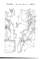
- FIG. 1 is a side view of a tractor mower combination utilizing the present invention
- FIG. 2 is a partial top view of the tractor mower combination shown in FIG. 1, with parts broken away for illustration purposes;
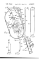
- FIG. 3 is a section view taken on the line III--III in FIG. 1;
- FIG. 4 is a view taken along the line IV--IV in FIG. 1;
- FIG. 5 is a section view taken along the line V--V in FIG. 4;
- FIG. 6 is an enlarged view of a baffle installed in the housing as shown in FIG. 4;
- FIG. 7 is an end view of the baffle shown in FIG. 6;
- FIG. 8 is an enlarged view of a baffle which is shown in its installed condition in the mower housing in FIG. 4;
- FIG. 9 is a front view of the baffle shown in FIG. 8.
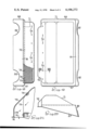
- FIG. 10 is a top view of the elbow part of a conduit between the mower housing and the grass catcher;
- FIG. 11 is the side view of the elbow part shown in FIG. 10;
- FIGS. 12 and 13 are section views through the elbow part in FIG. 10;
- FIG. 14 is a section view through the elbow part taken on line XIV--XIV in FIG. 11;
- FIGS. 15, 16 and 17 are section views taken on lines XV--XV, XVI--XVI and XVII--XVII in FIG. 4;
- FIGS. 18, 19 and 20 are rear, top and side views, respectively, of the cover of the grass catcher shown in FIGS. 1 and 2;
- FIG. 21 is a section view taken on the line XXI--XXI in FIG. 19.
- the tractor mower combination shown in FIGS. 1 and 2 includes a tractor 31 having a pair of drive wheels 32, 33 and a pair of steerable front wheels 34, 36.
- An operator's station 37 and a steering wheel 38 are provided at the rear of the tractor and an engine 39 is mounted on the front of the main frame 40 of the tractor 31.
- the engine 39 is drivingly connected to the rear drive wheels 32, 33 in a conventional manner by a drive train, not shown.
- the mower unit 41 is connected to the engine 39 through a V-belt 42 which drivingly engages pulleys 43, 44 secured for rotation with vertical shafts or spindles 46, 47 disposed to define laterally spaced vertical axes 46', 47'.
- the axis 47' closest to the discharge opening is spaced rearwardly of axis 46'.
- the front of the mower housing 51 of the mower unit 41 is suspended from the front axle 55 of the tractor 31 by a pair of transversely spaced links 52, only one of which is shown.
- the rear of the mower housing 51 is supported by a pair of ground wheels 53, one of which is mounted on a rearwardly extending leg of a transverse shaft or rod 54.
- An upright lever 56 is connected to rod 54 and is shiftable to any one of a plurality of positions of detented cooperation with a notched bracket 57 to achieve raising and lowering of the rear of the housing 51.
- the front of the mower housing 51 is simultaneously raised and lowered with the rear of the housing by action of a push-pull rod 57' operatively interconnecting the rod 54 and link 52.
- a grass catcher 61 is removably mounted on a bracket 62 secured to the rear part 63 of the tractor frame 40.
- a grass catcher frame 66 to which a flexible bag 67 is secured as by a zipper connection, includes a pair of downwardly extending cylindrical parts 68 which telescopically fit over a pair of laterally spaced upstanding posts 64 of the bracket 62. If it is desired to remove the grass catcher 61, the grass catcher frame 66 is lifted upwardly from the posts 64.
- the grass catcher 61 includes a molded plastic impervious cover 71 which has a rearwardly extending discharge port or hood 72 which extends substantially the full width of the cover 71. Referring also to FIGS.
- a vertical screen 73 is fastened by rivets 74 to the cover 71 to prevent grass clippings from being carried by exhausting air from the grass catcher.
- the air exhausted from the grass catcher is directed downwardly in the direction of arrow 75 in FIG. 21 through the downwardly facing vent or opening 76' of the exhaust hood 72 defined by parallel transverse vertical walls 172, 173.
- the size of the discharge opening is relatively large thereby (1) minimizing pressure differential between the inside and outside of the cover, and (2) providing a low discharge velocity for air exhausted from the grass catcher which minimizes entrainment of dust and clippings in the discharged air thus providing a cleaner environment for the operator and avoiding rapid build-up of grass clippings on the vent screen 73.
- the cover 71 has a downwardly extending apron 81 at the front thereof in which a pair of laterally spaced recesses 82 are formed for receiving a discharge tube such as the illustrated discharge conduit 76.
- the two recesses 82 permit the cover to be used for rear mounted grass catchers on mowers having either right or left discharging mower units.
- the cover 71 also includes laterally opposite tapered side walls 87, 88 which reinforce the front wall 81 and together therewith serves as a dust shield.
- the discharge conduit 76 includes two parts.
- a rear tubular part 78 of clear plastic has its rear end extending through an opening in the bag 67 and its front end is flexibly bent to an ellipitical cross-sectional shape and slipped over the elliptical rear end 146 of an elbow or elbow part 77 of the discharge conduit 76.
- the resiliency of the tubular part 78 causes it to grip the elbow part 77 with sufficient force to maintain the parts 77, 78 in telescopic assembled condition.
- the front of the elbow part is secured to the lateral side of the mower housing 51 by releasable fastening means such as bolts 84 and nuts 85.
- the elbow part is described in greater detail in a subsequent part of this description.
- the downwardly opening mower housing 51 includes a top wall 91, a front wall 92 and a rear wall 93. These walls terminate at one lateral side of the housing 51 in a discharge opening 94.
- a vertical lateral wall 95 closes off the side of the housing opposite the opening 94.
- a generally rectangular inlet opening 96 defined by the walls of the elbow part 77 of the conduit means 76, is in generally aligned relation to the lateral discharge opening 94 in the mower housing 51.
- the front wall 92 is actually a front vertical wall of a baffle 101 which includes a vertical end wall 102 disposed at an acute angle to the front wall 92.
- the baffle 101 is secured to the housing 51 by bolts 103 and nuts 104 and is used to modify an existing mower housing which had a lateral opening wider in the fore and aft direction than the desired opening 94. If it is desired to use the mower without a bagging attachment, the baffle 101 may be removed to permit the clippings to be dispersed in a wider pattern than would be the case of a housing having a narrower discharge opening. It should be understood, of course, that the housing 51 could be formed with the forward wall 105 disposed in the position of the wall 92 of the baffle 101, in which case, there would be no need for the baffle 101. A pair of identical blades 106, 106' are secured to the spindles 47, 46 by suitable nuts 107.
- the spindles 46, 47 are rotatably mounted by bearings, not shown, on the top wall 91 of the housing 51. As the blades are rotated their tips define a circular path indicated by the dash lines 108, 109. As appears in FIG. 4, the circles 108, 109 are closely adjacent the front wall 92 of the housing 51. It has been found that the position of the front wall of the housing in a closely adjacent or nearly tangential position to the tip paths of the blades 106 contributes to efficient movement of air and clippings to the discharge opening 94.
- Two other vertical baffles 111, 112 are also secured on the inside of the blade housing 51 by suitable fastening means in the form of bolts 103 and nuts 104.
- the baffle 111 provides a curved vertical wall 116 adjacent the path 108 of the blade 106 and also a curved vertical wall 117 adjacent the path 109 of the blade 106'.
- the baffle 111 is not new in the lawn mower industry and has heretofore been utilized to increase the efficiency of movement of air and clippings from the mower housing.
- baffle 112 is believed to be a new baffle which is employed to further increase the efficiency of movement of air and clippings from the mower housing 51.
- the baffle 112 includes a curved wall 113 and a straight wall 121 which direct the air and clippings propelled by rotation of the blade 106' in the direction indicated by arrows 126 from the mower housing 51 by way of tunnel 123 in the front upper part of the mower housing, which tunnel is substantially parallel to a plane through the axes 46', 47' of the spindles 46, 47.
- the vertical wall 121 of the baffle 112 serves as an air cutoff for the blade 106 and as part of the rear wall of the tunnel 123.
- the mower blade 106' has its radially outer ends bent whereby the trailing edges slope upwardly to form lift portions so as to provide a fan to lift the clippings and generate air movement of sufficient volume to entrain the cut particles of grass.
- the other blade 106 is similarly formed.
- the tunnel 123 above the blades 106, 106' in the front part of the mower housing is formed in part by providing two different elevations in the top wall 91 as shown in FIGS. 15 and 16 and partly by provision of the baffle 112.
- the part 191 of the top wall 91 of the housing 51 is higher than the part 192 of the top wall 91 and these parts 191, 192 are joined by a generally vertical wall section 193.
- the part 191 starts to slope downwardly starting at a point in front of spindle 46 and merges with part 192 of the top wall at a point laterally outward from spindle 46.
- the vertical wall 121 of baffle 112 serves as an air cutoff for the blade 106' whereby the blade delivers air to the tunnel 123 at a relatively high flow rate. Since the tunnel 123 is at the forward part of the blade housing 51 where the blades 106 and 106' sever the grass, the grass clippings are entrained in the relatively high volume movement of the air in the direction of the arrows 126 and move to the outlet 94 of the housing 51 and into the inlet opening 96 of the elbow part 77 of the discharge conduit 76.
- the elbow part 77 is a molded, relatively rigid plastic part which is contoured so as not to have dead spots. In other words, there is sufficient velocity of air blown throughout the interior of the elbow part to effectively convey clippings to tubular part 78 and thence to the grass catcher. This is achieved by sloping the top and bottom walls 152, 151 of the elbow part upwardly starting adjacent its intake opening 96 and at the same time curving the elbow part 77 in a rearward direction.
- the intake opening 96 is a generally elliptical or rectangular opening as illustrated in FIG. 12 which shows the cross-section of the elbow part at approximately 0° of the 90° elbow configuration, as viewed in FIG.
- the major axis 141 of the elliptical cross-section of the elbow part 77 changes its position from the generally horizontal disposition at the opening 96 to an upwardly and outwardly disposed position at an acute angle of 30° to the horizon, as shown in FIG. 13, to an upwardly and outwardly sloping position at section XIV--XIV, as shown in FIG. 14, which is at an angle greater than 45° in relation to the horizon.
- the cross-section of the elbow part changes gradually from a rectangular-elliptical shape at the longitudinal vertical section taken on line XII--XII at the start of the elbow curvature, wherein the major axis 141 is longitudinally and horizontally disposed, to an elliptical shape at approximately the 90° position of the elbow as viewed on line XIV--XIV, wherein the major axis 141 slopes upwardly and outwardly in relation to the center of curvature of the elbow part 77.
- the elbow part 77 maintains a substantially elliptical configuration from a point near its intake opening 96 through a predetermined number of degrees constituting a major portion of the curvature of the elbow part 77 and terminates in a curvilinear, rearward facing discharge opening 146'.
- material and air flowing through the elbow part to the grass catcher will be raised to a higher elevation at the laterally outer side of the end section 146 than at the side of the latter closest to the mower housing.
- the tunnel 123 slopes rearwardly from the closed side of the housing 51 to the discharge 94, and the front wall 144 of the elbow part 77 is a smooth continuation of the front wall 92 of the tunnel 123. This not only helps to avoid dead spots, where low velocity or eddy currents conditions may occur, but also gives an initial rearward component to the air and clippings entering the elbow.
- the illustrated tractor mower has two 18.5 inch blades which produce a 36 inch wide cut.
- the tubular part 78 of the discharge conduit has an internal cross-sectional area of 33 square inches and the cross-sectional area of the grass catcher cover vent opening 76' is 56 square inches.
- vent opening 76' is over one and one half times larger in the cross-sectional area than the cross-sectional area of the interior of the tubular part 78. More precisely the vent opening is 1.8 times as large as the tubular part in the cross-sectional area.
Landscapes
- Life Sciences & Earth Sciences (AREA)
- Environmental Sciences (AREA)
- Harvester Elements (AREA)
Abstract
Description
Claims (9)
Priority Applications (4)
| Application Number | Priority Date | Filing Date | Title |
|---|---|---|---|
| US05/747,694 US4106272A (en) | 1976-12-06 | 1976-12-06 | Grass collecting multiple blade mower without auxiliary blower means |
| CA284,492A CA1079981A (en) | 1976-12-06 | 1977-08-09 | Grass collecting multiple blade mower without auxiliary blower means |
| GB48770/77A GB1545670A (en) | 1976-12-06 | 1977-11-23 | Riding lawnmower tractor |
| FR7736612A FR2372586A1 (en) | 1976-12-06 | 1977-12-05 | SELF-PROPELLED LAWN MOWER WITH DRIVING STATION |
Applications Claiming Priority (1)
| Application Number | Priority Date | Filing Date | Title |
|---|---|---|---|
| US05/747,694 US4106272A (en) | 1976-12-06 | 1976-12-06 | Grass collecting multiple blade mower without auxiliary blower means |
Publications (1)
| Publication Number | Publication Date |
|---|---|
| US4106272A true US4106272A (en) | 1978-08-15 |
Family
ID=25006232
Family Applications (1)
| Application Number | Title | Priority Date | Filing Date |
|---|---|---|---|
| US05/747,694 Expired - Lifetime US4106272A (en) | 1976-12-06 | 1976-12-06 | Grass collecting multiple blade mower without auxiliary blower means |
Country Status (4)
| Country | Link |
|---|---|
| US (1) | US4106272A (en) |
| CA (1) | CA1079981A (en) |
| FR (1) | FR2372586A1 (en) |
| GB (1) | GB1545670A (en) |
Cited By (25)
| Publication number | Priority date | Publication date | Assignee | Title |
|---|---|---|---|---|
| US4250698A (en) * | 1978-10-13 | 1981-02-17 | Eastern Molding International, Inc. | Grass catcher |
| US4321783A (en) * | 1979-04-07 | 1982-03-30 | Kubota, Ltd. | Mid-mounted mower |
| US4393645A (en) * | 1981-08-19 | 1983-07-19 | Deere & Company | Rear bagger attachment for lawn mower |
| US4532755A (en) * | 1984-07-16 | 1985-08-06 | Simplicity Manufacturing, Inc. | Clipping collector for riding mower |
| US4570425A (en) * | 1983-06-09 | 1986-02-18 | Roseman Mower Corporation | Hydraulically operated gang mower trailer |
| US4589251A (en) * | 1983-12-02 | 1986-05-20 | Honda Giken Kogyo Kabushiki Kaisha | Grass bag attachment for combination lawn mower and tractor |
| US4614080A (en) * | 1983-12-01 | 1986-09-30 | Hoepfner Thomas L | Grass collector blower |
| EP0220754A1 (en) * | 1985-09-13 | 1987-05-06 | Gutbrod-Werke Gmbh | Tractor lawn mower with a rear-mounted grass catcher |
| USD290366S (en) | 1986-03-31 | 1987-06-16 | Hoepfner Thomas L | Combined grass collector and blower |
| JPS62113634U (en) * | 1986-01-13 | 1987-07-20 | ||
| US4693063A (en) * | 1985-01-17 | 1987-09-15 | Hoepfner Thomas L | Material collection apparatus |
| JPS63107117U (en) * | 1986-12-26 | 1988-07-11 | ||
| US4773205A (en) * | 1986-08-01 | 1988-09-27 | Outboard Marine Corporation | Anti-clogging means for bulk material flow duct |
| US4945716A (en) * | 1989-02-14 | 1990-08-07 | Kubota Ltd. | Lawn mower |
| USD311406S (en) | 1987-05-04 | 1990-10-16 | Hoepfner Thomas L | Combined grass catcher blower and chute |
| US5267429A (en) * | 1992-07-21 | 1993-12-07 | Deere & Company | Rear discharge mulching apparatus |
| US5511369A (en) * | 1994-11-21 | 1996-04-30 | Cerminara, Jr.; Frank | Chute to prevent clumping of grass ejected from a mower |
| US6148595A (en) * | 1998-12-11 | 2000-11-21 | Ransomes America Corporation | Passive distribution deflector for grass clippings collection system |
| US6481194B1 (en) | 2000-05-24 | 2002-11-19 | Deere & Company | Cutting implement height adjustment mechanism having grouped height selections |
| US6595737B1 (en) | 2001-10-31 | 2003-07-22 | Frank Parish | Dischargeable hopper system for vehicular apparatus |
| US20040016218A1 (en) * | 2002-07-29 | 2004-01-29 | Deere & Company, A Delaware Corporation | Access plate for an auger tube |
| WO2008045612A3 (en) * | 2006-10-10 | 2008-07-10 | Donna Vineis | Lawn mower |
| US9930831B2 (en) * | 2015-09-02 | 2018-04-03 | Deere & Company | Mower deck grass collector chute |
| CN111406502A (en) * | 2020-04-23 | 2020-07-14 | 深圳市伊乐农贸有限公司 | Lawn mower with function is collected to grass bits |
| US20250107482A1 (en) * | 2023-09-28 | 2025-04-03 | William E Clemons, JR. | Riding apparatus for mowing and pressure surface cleaning |
Families Citing this family (5)
| Publication number | Priority date | Publication date | Assignee | Title |
|---|---|---|---|---|
| DE7933824U1 (en) * | 1979-11-30 | 1981-04-30 | Wiedenmann Gmbh, 7901 Rammingen | Suction device for removing leaves, clippings or the like. |
| DE3043087C2 (en) * | 1980-11-14 | 1985-04-04 | Wiedenmann Gmbh, 7901 Rammingen | Suction channel for a mower |
| DE3419358C2 (en) * | 1983-06-27 | 1986-05-28 | Deere & Co., Moline, Ill., US, Niederlassung Deere & Co. European Office, 6800 Mannheim | Mower device |
| IT8323912U1 (en) * | 1983-12-20 | 1985-06-20 | Fedeli Luisa | IMPROVED STRUCTURE OF A ROTARY LAWN MOWER WITH A SEAT-ON DRIVER |
| FR2643213A1 (en) * | 1989-02-17 | 1990-08-24 | Eurl Duyck | Mower |
Citations (2)
| Publication number | Priority date | Publication date | Assignee | Title |
|---|---|---|---|---|
| US3461654A (en) * | 1967-03-15 | 1969-08-19 | M T & D Co The | Mechanism for raising and lowering cutter unit and for concurrently controlling operation of the cutter unit |
| US3716977A (en) * | 1971-11-08 | 1973-02-20 | Mcdonough Power Equipment Inc | Grass catcher assembly |
Family Cites Families (9)
| Publication number | Priority date | Publication date | Assignee | Title |
|---|---|---|---|---|
| US2898723A (en) * | 1956-06-15 | 1959-08-11 | Goodall Equipment Inc | Multiple bladed mower |
| US3522695A (en) * | 1965-10-22 | 1970-08-04 | Mast Foos Mfg Co Inc | Debris catcher |
| US3485018A (en) * | 1967-04-04 | 1969-12-23 | Black & Decker Mfg Co | Lawn mower deck housing |
| US3881304A (en) * | 1971-12-20 | 1975-05-06 | Homelawn Corp | Dumpable grass catcher |
| BE793182A (en) * | 1971-12-27 | 1973-04-16 | Lely Nv C Van Der | DEVICE FOR INCLUDING MATERIALS ON THE GROUND |
| US3958401A (en) * | 1974-09-05 | 1976-05-25 | Outboard Marine Corporation | Grass collection apparatus |
| US3934392A (en) * | 1974-11-04 | 1976-01-27 | International Harvester Company | Debris collector for lawn and garden machines |
| US3974631A (en) * | 1975-01-24 | 1976-08-17 | J. I. Case Company | Grass catcher assembly |
| CA1092368A (en) * | 1975-03-06 | 1980-12-30 | Earl H. Kidd | Multiple spindle rotary mower |
-
1976
- 1976-12-06 US US05/747,694 patent/US4106272A/en not_active Expired - Lifetime
-
1977
- 1977-08-09 CA CA284,492A patent/CA1079981A/en not_active Expired
- 1977-11-23 GB GB48770/77A patent/GB1545670A/en not_active Expired
- 1977-12-05 FR FR7736612A patent/FR2372586A1/en active Granted
Patent Citations (3)
| Publication number | Priority date | Publication date | Assignee | Title |
|---|---|---|---|---|
| US3461654A (en) * | 1967-03-15 | 1969-08-19 | M T & D Co The | Mechanism for raising and lowering cutter unit and for concurrently controlling operation of the cutter unit |
| US3716977A (en) * | 1971-11-08 | 1973-02-20 | Mcdonough Power Equipment Inc | Grass catcher assembly |
| US3716977B1 (en) * | 1971-11-08 | 1987-10-13 |
Cited By (27)
| Publication number | Priority date | Publication date | Assignee | Title |
|---|---|---|---|---|
| US4250698A (en) * | 1978-10-13 | 1981-02-17 | Eastern Molding International, Inc. | Grass catcher |
| US4321783A (en) * | 1979-04-07 | 1982-03-30 | Kubota, Ltd. | Mid-mounted mower |
| US4393645A (en) * | 1981-08-19 | 1983-07-19 | Deere & Company | Rear bagger attachment for lawn mower |
| US4570425A (en) * | 1983-06-09 | 1986-02-18 | Roseman Mower Corporation | Hydraulically operated gang mower trailer |
| US4614080A (en) * | 1983-12-01 | 1986-09-30 | Hoepfner Thomas L | Grass collector blower |
| US4589251A (en) * | 1983-12-02 | 1986-05-20 | Honda Giken Kogyo Kabushiki Kaisha | Grass bag attachment for combination lawn mower and tractor |
| US4532755A (en) * | 1984-07-16 | 1985-08-06 | Simplicity Manufacturing, Inc. | Clipping collector for riding mower |
| US4693063A (en) * | 1985-01-17 | 1987-09-15 | Hoepfner Thomas L | Material collection apparatus |
| EP0220754A1 (en) * | 1985-09-13 | 1987-05-06 | Gutbrod-Werke Gmbh | Tractor lawn mower with a rear-mounted grass catcher |
| US4738088A (en) * | 1985-09-13 | 1988-04-19 | Gutbrod-Werke GmbH Industriegelande | Lawn tractor with a rear mounted grass catcher |
| JPS62113634U (en) * | 1986-01-13 | 1987-07-20 | ||
| USD290366S (en) | 1986-03-31 | 1987-06-16 | Hoepfner Thomas L | Combined grass collector and blower |
| US4773205A (en) * | 1986-08-01 | 1988-09-27 | Outboard Marine Corporation | Anti-clogging means for bulk material flow duct |
| JPS63107117U (en) * | 1986-12-26 | 1988-07-11 | ||
| USD311406S (en) | 1987-05-04 | 1990-10-16 | Hoepfner Thomas L | Combined grass catcher blower and chute |
| US4945716A (en) * | 1989-02-14 | 1990-08-07 | Kubota Ltd. | Lawn mower |
| US5267429A (en) * | 1992-07-21 | 1993-12-07 | Deere & Company | Rear discharge mulching apparatus |
| US5511369A (en) * | 1994-11-21 | 1996-04-30 | Cerminara, Jr.; Frank | Chute to prevent clumping of grass ejected from a mower |
| US6148595A (en) * | 1998-12-11 | 2000-11-21 | Ransomes America Corporation | Passive distribution deflector for grass clippings collection system |
| US6481194B1 (en) | 2000-05-24 | 2002-11-19 | Deere & Company | Cutting implement height adjustment mechanism having grouped height selections |
| US6595737B1 (en) | 2001-10-31 | 2003-07-22 | Frank Parish | Dischargeable hopper system for vehicular apparatus |
| US20040016218A1 (en) * | 2002-07-29 | 2004-01-29 | Deere & Company, A Delaware Corporation | Access plate for an auger tube |
| US6796114B2 (en) * | 2002-07-29 | 2004-09-28 | Deere & Company | Access plate for an auger tube |
| WO2008045612A3 (en) * | 2006-10-10 | 2008-07-10 | Donna Vineis | Lawn mower |
| US9930831B2 (en) * | 2015-09-02 | 2018-04-03 | Deere & Company | Mower deck grass collector chute |
| CN111406502A (en) * | 2020-04-23 | 2020-07-14 | 深圳市伊乐农贸有限公司 | Lawn mower with function is collected to grass bits |
| US20250107482A1 (en) * | 2023-09-28 | 2025-04-03 | William E Clemons, JR. | Riding apparatus for mowing and pressure surface cleaning |
Also Published As
| Publication number | Publication date |
|---|---|
| GB1545670A (en) | 1979-05-10 |
| FR2372586B1 (en) | 1983-07-22 |
| CA1079981A (en) | 1980-06-24 |
| FR2372586A1 (en) | 1978-06-30 |
Similar Documents
| Publication | Publication Date | Title |
|---|---|---|
| US4106272A (en) | Grass collecting multiple blade mower without auxiliary blower means | |
| US3987606A (en) | Grass clipping collection apparatus | |
| US3757503A (en) | Lawnmower and grass collector | |
| EP0501674B1 (en) | Grass cutting machines | |
| US4245455A (en) | Lawn mower | |
| US3934392A (en) | Debris collector for lawn and garden machines | |
| US4158279A (en) | Riding mower with grass collecting system | |
| CA1045833A (en) | Combination mower and catcher | |
| US2760327A (en) | Housing for disc type power mower | |
| US5685134A (en) | Simultaneous litter removal and grass cutting apparatus | |
| US4054023A (en) | Grass collection apparatus | |
| US3958401A (en) | Grass collection apparatus | |
| US4173111A (en) | Vented grass-catcher cover | |
| US2720070A (en) | Forage crop cutting and conveying device | |
| US3421302A (en) | Lawn mower grass catching bag | |
| US4974403A (en) | Grass cutting system having a grass catcher | |
| US4259832A (en) | Grass collection apparatus | |
| US6748669B1 (en) | Hovering drying machine | |
| US5465562A (en) | Nut harvester | |
| US5592805A (en) | Nut harvester | |
| GB2053643A (en) | Lawn mower | |
| JPH08158337A (en) | Sweeper | |
| US3352094A (en) | Nut harvesting apparatus | |
| US3665687A (en) | Blower attachment for reel type lawn mower | |
| JPH04645Y2 (en) |
Legal Events
| Date | Code | Title | Description |
|---|---|---|---|
| AS | Assignment |
Owner name: WOODS KATHLEEN D., AS TRUSTEE Free format text: SECURITY INTEREST;ASSIGNOR:ALLIS-CHALMERS CORPORATION A DE CORP.;REEL/FRAME:004149/0001 Effective date: 19830329 Owner name: CONNECTICUT NATIONAL BANK THE, A NATIONAL BANKING Free format text: SECURITY INTEREST;ASSIGNOR:ALLIS-CHALMERS CORPORATION A DE CORP.;REEL/FRAME:004149/0001 Effective date: 19830329 |
|
| AS | Assignment |
Owner name: FIRST NATIONAL BANK OF BOSTON THE (THE BANK) Free format text: SECURITY INTEREST;ASSIGNOR:SIMPLICITY MANUFACTURING INC.;REEL/FRAME:004475/0061 Effective date: 19851022 Owner name: SIMPLICITY MANUFACTURING COMPANY, PORT WASHINGTON, Free format text: ASSIGNMENT OF ASSIGNORS INTEREST.;ASSIGNOR:ALLIS-CHALMERS CORPORATION A CORP OF DE;REEL/FRAME:004472/0189 Effective date: 19830210 |
|
| AS | Assignment |
Owner name: SIMPLICITY MAUFACTURING, INC. Free format text: RELEASED BY SECURED PARTY;ASSIGNOR:MANUFACTURERS HANOVER LEASING CORPORATION;REEL/FRAME:004473/0822 Effective date: 19851023 |
|
| STCF | Information on status: patent grant |
Free format text: PATENTED FILE - (OLD CASE ADDED FOR FILE TRACKING PURPOSES) |
|
| AS | Assignment |
Owner name: SIMPLITICY MANUFACTURING, INC. Free format text: ASSIGNMENT OF ASSIGNORS INTEREST.;ASSIGNOR:FOWLER, PETE H., AS TRUSTEE;REEL/FRAME:004528/0858 Effective date: 19851023 |
|
| AS | Assignment |
Owner name: SIMPLITICY MANUFACTURING, INC. ("SIMPLICITY") Free format text: RELEASED BY SECURED PARTY;ASSIGNOR:CONNECTICUT NATIONAL BANK THE;REEL/FRAME:004553/0693 Effective date: 19860304 |
|
| AS | Assignment |
Owner name: FIRST NATIONAL BANK OF BOSTON, THE, Free format text: SECURITY INTEREST;ASSIGNOR:SIMPLICITY MANUFACTURING, INC.;REEL/FRAME:005559/0376 Effective date: 19910107 |
|
| AS | Assignment |
Owner name: BARCLAYS BUSINESS CREDIT, INC., WISCONSIN Free format text: SECURITY INTEREST;ASSIGNOR:SIMPLICITY MANUFACTURING, INC.;REEL/FRAME:006661/0635 Effective date: 19930609 |