US4100818A - Drive system - Google Patents
Drive system Download PDFInfo
- Publication number
- US4100818A US4100818A US05/722,937 US72293776A US4100818A US 4100818 A US4100818 A US 4100818A US 72293776 A US72293776 A US 72293776A US 4100818 A US4100818 A US 4100818A
- Authority
- US
- United States
- Prior art keywords
- drive
- speed
- disc spring
- flange
- movable
- Prior art date
- Legal status (The legal status is an assumption and is not a legal conclusion. Google has not performed a legal analysis and makes no representation as to the accuracy of the status listed.)
- Expired - Lifetime
Links
Images


Classifications
-
- F—MECHANICAL ENGINEERING; LIGHTING; HEATING; WEAPONS; BLASTING
- F16—ENGINEERING ELEMENTS AND UNITS; GENERAL MEASURES FOR PRODUCING AND MAINTAINING EFFECTIVE FUNCTIONING OF MACHINES OR INSTALLATIONS; THERMAL INSULATION IN GENERAL
- F16H—GEARING
- F16H9/00—Gearings for conveying rotary motion with variable gear ratio, or for reversing rotary motion, by endless flexible members
- F16H9/02—Gearings for conveying rotary motion with variable gear ratio, or for reversing rotary motion, by endless flexible members without members having orbital motion
- F16H9/04—Gearings for conveying rotary motion with variable gear ratio, or for reversing rotary motion, by endless flexible members without members having orbital motion using belts, V-belts, or ropes
- F16H9/12—Gearings for conveying rotary motion with variable gear ratio, or for reversing rotary motion, by endless flexible members without members having orbital motion using belts, V-belts, or ropes engaging a pulley built-up out of relatively axially-adjustable parts in which the belt engages the opposite flanges of the pulley directly without interposed belt-supporting members
- F16H9/16—Gearings for conveying rotary motion with variable gear ratio, or for reversing rotary motion, by endless flexible members without members having orbital motion using belts, V-belts, or ropes engaging a pulley built-up out of relatively axially-adjustable parts in which the belt engages the opposite flanges of the pulley directly without interposed belt-supporting members using two pulleys, both built-up out of adjustable conical parts
- F16H9/18—Gearings for conveying rotary motion with variable gear ratio, or for reversing rotary motion, by endless flexible members without members having orbital motion using belts, V-belts, or ropes engaging a pulley built-up out of relatively axially-adjustable parts in which the belt engages the opposite flanges of the pulley directly without interposed belt-supporting members using two pulleys, both built-up out of adjustable conical parts only one flange of each pulley being adjustable
Definitions
- the accessory drive provides at least a linear ratio between the speed (rpm) of the engine and the speed (rpm) of the accessory driven shaft.
- rpm speed of the engine
- rpm speed of the accessory driven shaft.
- OEM original equipment
- each accessory normally has a most efficient or optimum rpm range and with normal systems the accessory is not within this range due to wide variation in the input speed.
- an accessory drive system For an accessory drive system to meet requirements for use in modern vehicles, it should be small enough to fit in present-day engine compartments without any substantial modifications, it should be relatively inexpensive, it should be susceptible of mass production and adjustable to modern assembly techniques, it should have long life, and it should produce a drive from the engine to the accessories which increases their speeds in approximately a linear relation with increasing engine speed at low rpm but which produces relatively constant accessory speeds as the engine speed increases above a predetermined point throughout the normal vehicle driving range.
- the present invention meets all these criteria.
- the drive of this invention is to be distinguished from the conventional variable pulley transmission as is presently used in, for example, off-the-road vehicles or has been proposed for the transmission for transmitting power from an engine to the driving mechanism of a vehicle, whether they are wheels, lugs or other devices.
- the engine rpm is increased and, at the same time, the rpm of the driving mechanism is increased at an even faster rate. Further, until a certain driveR pulley rpm is achieved, no power is transmitted to the driveN pulley.
- This invention relates to a drive system for transmitting torque from a prime mover, such as an automobile engine, to accessories associated therewith. It comprises, a relatively inexpensive assembly of variable diameter pulleys connected by a drive belt.
- the assembly is preferably constructed mainly of stamped metal parts; the belt is generally the only part which will require replacement even after a considerable length of operating time.
- the drive system of the present invention comprises a pair of variable pitch diameter pulleys, one, a driveR, associated with the drive shaft and another, a driveN, associated with a driven shaft (which drives the "accessory package").
- Each of the variable pulleys has a fixed flange and a movable flange.
- the movable flange of each pulley is mounted on its associated shaft by a bushing, preferably constructed of a non-metallic material such as nylon or the like.
- a suitably pre-loaded disc spring urges the movable flange of the driveN pulley axially toward the fixed flange thereof.
- the movable flange of the driveR pulley is associated with the disc spring having a plurality of attached weights.
- the spring in its rest position, urges the movable flange of the driveR pulley toward the fixed flange thereof. At a predetermined speed, the weights move outwardly because of centrifugal force, and the movable flange is urged axially away from the fixed flange. The movement of the weights is limited by stop means, and thus axial movement of the movable flange from its associated fixed flange is also limited.
- Movement of the movable flanges of the pulleys permits the drive belt connecting the pulleys to shift positions relative to the respective shafts and thus provide a different drive ratio between the shafts.
- the weights which control the accessory drive mechanism are on the driveR pulley only, so that the control of speed ratios between the pulleys is from the drive only, i.e., from the drive shaft.
- the device is drive shaft speed sensitive.
- the spring rate of the driveR disc spring is substantially continuously positive in slope and the spring has a h/t ratio of about one (1), where h is the initial formed heights and t is the thickness of the spring.
- the driveR and driveN pulleys rotate at a fixed ratio at relatively low motor speeds, as for example, up to about 1000 rpm.
- the weights attached to the disc spring of the driveR pulley begin to move outwardly.
- the driveR pulley continues to rotate at the same speed as the drive shaft while the driveN pulley rotates at a substantially uniform speed of about 1000 rpm. This condition prevails until the drive shaft speed becomes very high, normally associated with vehicle speeds in excess of the national speed limit.
- the weights At an elevated speed, such for example, at about a drive shaft speed of 3000 rpm, the weights have reached their most outward positions, and thereafter the speed of the driveN pulley then increases with further increases in the drive shaft speed but at a reduced lower ratio as compared to the drive shaft speed.
- the crankshaft speed In automobiles built in the United States of America the crankshaft speed, at a vehicle speed of about 55 miles per hour, is generally below 3000 rpm.
- the accessories which are each driven at different rpms (determined by the diameter of the specific pulley associated respectively therewith) depending on their function are generally rotated at substantially constant rpms.
- each accessory can be driven at its optimum or maximum efficiency rpm range over the usual crankshaft speed range of the vehicle.
- a device constructed according to this invention and according to the specific embodiment installed in a 1974 Nova has been road tested for at least 15,000 miles. During the road testing, all accessories including air conditioning have been operated. An energy savings of about 10% has been realized as compared with the same vehicle with the standard accessory drive driving the same accessories.
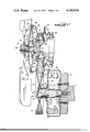
- FIG. 1 is a sectional view (parts of which are omitted for clarity) through a drive system according to this invention at idle position;
- FIG. 2 is a sectional view (parts of which are omitted for clarity) through a drive system according to this invention at one operating position;
- FIG. 3 is a plan view of a disc spring useable in the system of FIG. 1;
- FIG. 3A is a partial view of the rim of a spring retainer useable with the spring of FIG. 3;
- FIG. 4 is a sectional view of the spring of FIG. 3 taken on line 4--4 of FIG. 3 illustrating the spring before being loaded in the drive assembly;
- FIG. 5 is a view of a pilot hub of the invention.
- FIG. 5A is a perspective view of the outlined portion of FIG. 5;
- FIG. 6 is a set of curves of a specific drive system, drive rpm plotted against equivalent accessory driven rpm or, alternatively, accessory drive shaft rpm, one curve of which is the usual linear relationship and the other of which is a curve obtained using the system of this invention;
- FIG. 7 is a curve in which load is plotted against deflection of a driveR spring for a specific drive system for a drive constructed according to this invention.
- FIG. 8 is a curve in which load is plotted against deflection of a driveN spring for a specific drive system for a drive constructed according to this invention.
- FIG. 9 shows spring rate curves of a coil spring, a positive rate disc spring as used in this invention, a zero rate disc spring, and a typical Belleville spring;
- FIG. 10 is a curve showing the speed relationship between the driveR and the driveN pulleys in a conventional variable pulley transmission.
- FIG. 1 there is illustrated a preferred embodiment of the invention. Illustrated there is a drive shaft 10 adapted to be connected to the crankshaft 11 through the usual vibration damper 12 of, for example, an automobile engine (not shown). Associated with the crankshaft is a variable driveR pulley, generally identified as 13, which comprises a fixed flange 14 and a movable flange 16. The flange 14 is received on a reduced shaft portion 18 on drive shaft 10 to abut a shoulder 20 formed in the drive shaft. Flange 14 is held in position on shaft 10 by a bolt 22 in threaded engagement with a threaded bore 24 and a washer 26.
- a bolt 22 in threaded engagement with a threaded bore 24 and a washer 26.
- the movable flange 16 is press fitted onto a cylindrical sleeve 30 mounted on a bushing means 32 surrounding the shaft 10.
- the bushing means 32 is preferably constructed of a suitable material, such as nylon or the like and may comprise a single part.
- the flange 16, together with the sleeve 30, is axially movable relative to the fixed flange 14 and the shaft 10.
- a pivot or drive hub 34 is fixed to a cylindrical portion 36 of the flange 16, as for example by welding.
- the hub 34 comprises essentially a thrust ring or washer 38 with fingers or drive tangs 40 extending therefrom.
- An actuator mechanism for the movable flange 16 includes a cup-shaped, spring retainer or drive member 42 preferably of stamped steel is fixed to shaft 10 as for example by welding, and bolted to the vibration damper 12; the periphery of the retainer 42 terminates in an enlarged rim 44.
- the rim 44 receives and is engaged by the outer peripheral rim 45A of a disc spring 46; the rim 45A being formed with one or more flats 45B which cooperate with the flats 44A of the drive member 42 to provide a positive driving coupling between the spring 46 and the drive member 42.
- spring 46 has a plurality of inwardly extending fingers 54 which terminate in a central opening 48 of a dimension to surround the sleeve 30.
- a plurality of radial slots 50 each of which terminate in an enlarged opening 52 at the outer end define the plurality of radial fingers 54.
- a plurality of weights 56 having portions extending through the openings 52 are attached, as by swagging, coining, riveting, or the like to the spring 46, and the spring 46 is coupled to the movable flange 16 by means of the pivot hub 34, i.e., a tang 40 extends through a slot 50 and a finger engages the outer surface 58 of the washer 38, the surface 58 acting as a fulcrum, as will be explained.
- One weight 56 per opening 52 may be provided; a lesser number of weights can be used, as necessary to perform the function to be described.
- the actuator mechanism for the movable flange 16 thus includes the sheet metal drum 42 described above as a spring retainer or drive member having disposed therein disc spring 46 and weights 56.
- the length of the cylindrical portion 36 is chosen to properly pre-load the spring 46. In its pre-loaded condition, the spring is compressed from its initial formed condition, thus lessening the height of the cone, as such, it maintains pressure on the movable flange 16 to prevent slippage between the drive belt 88 and the pulley flanges 14 and 16.
- Torque transmission between the fixed pulley flange 14 and the movable pulley flange 16 occurs due to the positive drive coupling of the flats 45b and 44a at the outer rim of the disc spring 46 and the corresponding rim 44 of the retainer 42, respectively.
- FIG. 1 also illustrates a driven shaft 70, suitably supported by appropriate journals (not shown), having affixed thereto, for illustrative and exemplitive purposes only, a multibladed fan 72.
- the fan 72 has a circular hub 74 and is affixed to the shaft 70 by a nut 76 engaging a threaded portion 78 of the shaft 70.
- the fan 72 may be keyed or otherwise positively connected to the shaft 70 if necessary or desirable.
- a pulley 80 is affixed to the shaft 70 by a hub 81 and receives one or more V-belts (not shown) for driving one or more accessories, for example, a water pump, air conditioner compressor, generator, power steering pump or the like (not shown).
- the pulley 80 is illustrated as being constructed of stamped sheet steel, it may be constructed of cast iron, or other suitable material without departing from the spirit of the invention.
- each accessory may be driven at a different speed which would of course be the optimum or maximum efficiency speed for that accessory; for purposes of description, this is related to "equivalent accessory speed” or the speed of the shaft 70.
- variable driveN pulley Associated with the driven shaft 70 is a variable driveN pulley, generally identified as 82, which comprises a fixed flange 84 and a movable flange 86. Torque is transmitted from the pulley 13 to pulley 82 by a drive belt 88 of usual construction. The frictional engagement between the sides to the belt and the flanges provides the torque transmission.
- the fixed flange 84 is illustrated as being spot welded to the pulley 80; optionally, it may be an integral part if desired.
- the movable flange 86 has a cylindrical hub portion 90 which surrounds a cylindrical portion 92 of the pulley 80.
- a bushing 94 constructed of nylon or the like, is interposed between the portion 92 and the hub 90.
- the movable flange 86 has a forwardly extending rim 96 which is received in a cup-like shroud 98 having a cylindrical hub or bearing support 100 surrounding the shaft 70.
- a bearing 102 is positioned between the hub 100 and a sleeve 101 surrounding the shaft 70.
- Abutting the forwardly extending rim 96 of the flange 86 of the pulley 82 and within the shroud 98 is a disc spring 104 of a construction similar to the disc spring 46, earlier described.
- the spring 104 is not separately illustrated as is the spring 46.
- the spring 104 has a plurality of radially inwardly extending fingers 112 which terminate in a central opening 106 of a size to be positioned over the shaft 70.
- the spring 104 has a plurality of open-ended slots 108 each terminating in enlarged openings 110 and defining the radial fingers 112.
- a pivot or drive hub 114 similar to that illustrated in FIG. 5 surrounds the shaft 70, and is clamped to the shaft 70 by the sleeve 101 and hubs 74 and 81.
- the hub may be keyed or otherwise positively connected to the shaft 70, if necessary or desirable.
- the hub 114 has fingers or tangs 116 each of which engages a slot 108 and arcuate surfaced pivot portions 118, each having a surface 120 engaging the face of a spring finger 112.
- the pivot surfaces 118 act as fulcrums for the spring 104.
- the spring 104 also has rim flats to provide a positive driving coupling with rim flats on the member or shroud 98.
- the spring 104 is pre-loaded by selecting the length of the sleeve 101 and shoulder 81 and by tightening the nut 76 to properly position the parts as is illustrated in FIG. 1, (the idle condition).
- the spring is pre-loaded to a degree that it passes through center and such that it always exerts a force against the flange 86.
- the drive belt 88 provides the drive between the driveR pulley 12 and the driveN pulley 82, the drive ratio between the pulleys 13 and 82 being dependent on the position of the drive belt 88 relative thereto, which is dependent on the spacing of the flanges of the pulleys 12 and 82.
- the driveN pulley 82 always maintains tension against the belt 88.
- the shifting of the flange spacing of both pulleys 13 and 82 is controlled by the speed of the driveR shaft 10.
- the ratio of the driveR pulley 13 and driveN pulley 82 speeds is substantially the same (see FIG. 6) from zero engine speed to a predetermined, first engine speed. As engine speed increases beyond that first predetermined speed, centrifugal force causes the weights 56 to deflect outwardly gradually with increasing force as the speed increases. The spring 46 gradually from its FIG. 1 position is deflected toward the FIG. 2 position.
- DriveR rotation causes centrifugal forces to act at the nominal center of gravity of the weights 56 which are attached to the driveR pulley.
- the centrifugal force acts through an increasing (changing) effective radius due to the geometry of the weights and is balanced against the (positive) spring rates of the driveR and driveN disc springs 46 and 104, respectively.
- the forces acting on the driveR spring cause a change in movable flange axial position and a change in the driveR pulley pitch diameter.
- the fixed length belt shifts on the driveN pulley changing the driveR-driveN speed ratios.
- the weights, center of gravity geometry, spring rates and flange pressures are selected so as to produce a "controlled" driveN speed responsive to the driveR speeds.
- the weights 56 move outwardly, assuming that the engine speed is increasing, until they contact the spring retainer 42 -- see FIG. 2 -- at which time the spring 46 has deflected through center to its second maximum position (the first maximum or idle position being as illustrated in FIG. 1).
- the drive ratio again becomes fixed because the belt has reached its FIG. 2 position, and a linear ratio, less than the initial 1 to 1 is again established between the pulleys.
- the speed of the driveN pulley varies in accordance with the fixed reduced ratio with further increases in the speed of the driveR pulley 13.
- segment a of the curve shows the drive ratio according to this invention to be substantially 1:1.25 at crankshaft speeds up to about 1000 rpm.
- the drive ratio begins to change to maintain a substantially uniform driveN pulley speed, up to about 3000 rpm represented by segment b.
- the drive ratio becomes fixed at a reduced ratio of less than 1 to 1:25 as represented by segment c of the curve. The ultimate rpm of the driveN pulley never reaches the rpm of the driveR.
- the particular curve of speed ratios between input speed of about 1000 rpm and 3000 rpm reflects the interaction of the several forces of the drive system, i.e., the belt forces, the spring forces and the centrifugal forces. It can be a straight, horizontal curve under some conditions.
- the idle pitch diameters of the driveR and driveN pulleys are of such diameters to provide a 1 to 1.25 drive speed ratio between the driveR and driveN shafts as is the case in the preferred embodiment
- the curve is a straight line, as shown by segment a of FIG. 6.
- centrifugal force acts to move the weights 56 outwardly toward their maximum outward positions.
- the effective pitch diameter of the driveR pulley becomes increasingly smaller since the belt tension and reduction in spring force will cause the belt to move closer to the driveR shaft.
- the effective pitch diameter of the driveN pulley increases.
- the second fixed ratio can be determined from the lock up speed, of the driveR shaft which in the illustration is 3000 rpm and the lock up speed of the driveN shaft, i.e., about 1000 rpm (ideally) to be determined by the particular accessory manufacturer or the manufacturer of the vehicle.
- the lock up ratio or ratio reached at 3000 RPM of driveR pulley to driveN pulley is about 3 to 1.
- the vehicle speed at a crankshaft speed of about 1300 rpm is approximately 30 miles per hour and at a crankshaft speed of about 3,000 rpm is approximately 75 miles per hour.
- the broken line curve illustrates a conventional drive ratio between the crankshaft and the driveN shaft from which the accessories are driven, i.e., a continual 1 to 1:25 ratio in which the effective speed of the accessories increases with the crankshaft speed at this fixed ratio.
- the disc springs used in the preferred embodiment of this invention have an h/t (formed height of the unloaded spring to thickness) ratio of about one, expressed in the same units of measure, as indicated in FIG. 4.
- the spring rate of such disc springs in the preferred embodiment is positive i.e., is continuously positive in slope as is illustrated in FIGS. 7 and 8; and can be compared to the curves of spring rates of other types of springs, as for example, typical Belleville springs, corrugated Belleville springs, and typical coil springs, the spring rate curves of which are illustrated in FIG. 9.
- FIGS. 7 and 8 are load v. deflection curves for the preferred embodiment driveR disc spring 46 and the driveN disc spring 104, respectively. These are the spring curves to produce the results in FIG. 6. While the springs 46 and 104 are physically similar in construction, except for thickness, they are preloaded to different amounts, as indicated in the curves when the drive system of this invention is assembled for installation in a vehicle.
- the spring 46 is preloaded as explained to a particular deflection D; it must maintain a force on the movable pulley 16 at idle speeds, so that slippage of the belt is minimized. At a certain crankshaft rpm, the spring 46 is deflected by centrifugal force acting on the weights 56 to a second deflection D-1. The curve between the idle and fully shifted positions is positive and generally linear. There is no deflection surge or snap action; the deflection is gradual.
- the spring 104 is loaded through center to a particular deflection d, so as to continually exert a force against the movable pulley flange 86.
- d the tension on the belt 88 decreases due to the change occurring in the driveR pulley
- the flange 86 is urged toward the flange 84, such that the deflection of the spring 104 decreases generally uniformly with little decrease in load between the preload or idle positon (FIG. 1) and the high speed position (FIG. 2).
- the high speed deflection is indicated as d-1.
- the curves of FIGS. 6, 7 and 8 relate to a specific example of the drive of this invention.
- the diameter of the driveR pulley 13 is 7.125 inches
- the diameter of the driveN pulley 82 is 7.440 inches.
- the driveR spring 46 has an outer diameter of 7.810 inches while the driveN spring 104 has an outer diameter of 7.810 inches.
- Each weight 56 is 90 grams; there are 18 weights, located 0.195 inch from the end of each slot in the driveR spring 46.
- the h/t ratio of the driveR spring is 1.024; h being nominally 0.128 inch and t being nominally 0.125 inch.
- the h/t ratio of the driveN spring is 1.223; h being nominally 0.115 inch and t being nominally 0.094 inch.
- the belt used in this example is a 16 26 V 341. This belt is 1 inch wide, has a 26° included angle, is a V-belt with a pitch length of 34.1 inches.
- Tests to determine the advantages from using this invention have been conducted by installing drive systems as per the example given in a 1974 Chevrolet Nova, 350 C.I.D. engine with an air pump and an automatic transmission and of course, the normal accessories, such as air conditioning, a water pump, power steering, alternator and fan. Tests have been conducted with the air conditioning operating and non-operating (from the dash controls). The rear axle ratio was 2.73,
- FIG. 9 illustrates load v. deflection curves for various springs.
- Curve A is for a typical Belleville spring; note that a portion of the curve is negative.
- Curve B is a positive rate disc spring; similar to that used herein.
- Curve C is a curve for another disc spring having a portion of zero rate.
- Curve D is an ideal curve for a coil spring a linear relationship exists between load and deflection; it does not indicate instabilities which may occur during use which are indicated in the broken line curve designated D 1 .
- FIG. 10 illustrates the speed relationship between the driveR and driveN pulleys in a conventional variable pulley transmission. As the driveR rpm increases, the driveN rpm increases at an even faster rate; until the driveR pulley rpm reaches a certain value, no power is transmitted to the driveN pulley.
Landscapes
- Engineering & Computer Science (AREA)
- General Engineering & Computer Science (AREA)
- Mechanical Engineering (AREA)
- Transmissions By Endless Flexible Members (AREA)
- Auxiliary Drives, Propulsion Controls, And Safety Devices (AREA)
Priority Applications (11)
| Application Number | Priority Date | Filing Date | Title |
|---|---|---|---|
| US05/722,937 US4100818A (en) | 1976-09-13 | 1976-09-13 | Drive system |
| GB3182877A GB1558530A (en) | 1975-06-11 | 1977-07-28 | Expanding pulley drive system |
| AU27427/77A AU508654B2 (en) | 1976-09-13 | 1977-07-28 | Drive system |
| CA283,772A CA1067724A (en) | 1976-09-13 | 1977-07-29 | Drive system |
| IT7730267A IT1114923B (it) | 1976-09-13 | 1977-08-25 | Sistema di comando |
| AR269109A AR213977A1 (es) | 1976-09-13 | 1977-09-06 | Mejoras en aparato para impulsar accesorios |
| SE7710061A SE7710061L (sv) | 1976-09-13 | 1977-09-07 | Drivarrangemang |
| BR7706052A BR7706052A (pt) | 1976-09-13 | 1977-09-12 | Conjunto de polia variavel |
| FR7727509A FR2364136A2 (fr) | 1975-06-11 | 1977-09-12 | Dispositif d'entrainement d'equipements auxiliaires, notamment pour automobiles |
| JP11041277A JPS5335863A (en) | 1976-09-13 | 1977-09-13 | Driving gear |
| DE19772741146 DE2741146C2 (de) | 1975-06-11 | 1977-09-13 | Kegelscheibenumschlingungsgetriebe |
Applications Claiming Priority (1)
| Application Number | Priority Date | Filing Date | Title |
|---|---|---|---|
| US05/722,937 US4100818A (en) | 1976-09-13 | 1976-09-13 | Drive system |
Publications (1)
| Publication Number | Publication Date |
|---|---|
| US4100818A true US4100818A (en) | 1978-07-18 |
Family
ID=24904061
Family Applications (1)
| Application Number | Title | Priority Date | Filing Date |
|---|---|---|---|
| US05/722,937 Expired - Lifetime US4100818A (en) | 1975-06-11 | 1976-09-13 | Drive system |
Country Status (8)
| Country | Link |
|---|---|
| US (1) | US4100818A (es) |
| JP (1) | JPS5335863A (es) |
| AR (1) | AR213977A1 (es) |
| AU (1) | AU508654B2 (es) |
| BR (1) | BR7706052A (es) |
| CA (1) | CA1067724A (es) |
| IT (1) | IT1114923B (es) |
| SE (1) | SE7710061L (es) |
Cited By (10)
| Publication number | Priority date | Publication date | Assignee | Title |
|---|---|---|---|---|
| US4216678A (en) * | 1978-04-17 | 1980-08-12 | Borg-Warner Corporation | Drive system |
| US4384862A (en) * | 1979-07-02 | 1983-05-24 | Aisin Seiki Kabushiki Kaisha | Centrifugal operating device |
| US4475893A (en) * | 1979-05-23 | 1984-10-09 | Honda Giken Kogyo Kabushiki Kaisha | Power transmission for two-wheeled vehicle |
| US4569670A (en) * | 1984-05-31 | 1986-02-11 | Borg-Warner Corporation | Variable pulley accessory drive |
| US20050008823A1 (en) * | 2003-07-08 | 2005-01-13 | Schwar Ronald C. | Apparatus and method for attaching filamentary members to a substrate |
| US20050181905A1 (en) * | 2004-02-18 | 2005-08-18 | Imtiaz Ali | Transmission and constant speed accessory drive |
| US20090194210A1 (en) * | 2008-02-06 | 2009-08-06 | Montross S Sam | Disposable luggage wrap |
| US20130079182A1 (en) * | 2011-09-23 | 2013-03-28 | Briggs & Stratton Corporation | Pulley system for outdoor power equipment |
| US20160059808A1 (en) * | 2014-09-01 | 2016-03-03 | Aisin Seiki Kabushiki Kaisha | Vehicle body reinforcement apparatus |
| US20170023120A1 (en) * | 2015-07-20 | 2017-01-26 | Dennis Zulawski | Drive clutch |
Citations (8)
| Publication number | Priority date | Publication date | Assignee | Title |
|---|---|---|---|---|
| US2101084A (en) * | 1934-08-11 | 1937-12-07 | William F Hackett | Constant speed controlled drive |
| US2256699A (en) * | 1939-11-13 | 1941-09-23 | Gen Motors Corp | V belt pulley |
| US2553505A (en) * | 1949-03-17 | 1951-05-15 | Charles H Miner | Centrifugally controlled device |
| US3599504A (en) * | 1970-02-02 | 1971-08-17 | Borg Warner | Automatic transmission |
| US3664206A (en) * | 1970-06-25 | 1972-05-23 | Borg Warner | Accessory drive mechanism |
| US3747731A (en) * | 1972-01-26 | 1973-07-24 | Borg Warner | Constant speed centrifugal clutch |
| GB1456796A (en) | 1974-05-16 | 1976-11-24 | Daimler Benz Ag | Adjustable drive for auxiliary devices associated with internal combustion engines |
| US4020711A (en) * | 1975-06-11 | 1977-05-03 | Borg-Warner Corporation | Drive system |
-
1976
- 1976-09-13 US US05/722,937 patent/US4100818A/en not_active Expired - Lifetime
-
1977
- 1977-07-28 AU AU27427/77A patent/AU508654B2/en not_active Expired
- 1977-07-29 CA CA283,772A patent/CA1067724A/en not_active Expired
- 1977-08-25 IT IT7730267A patent/IT1114923B/it active
- 1977-09-06 AR AR269109A patent/AR213977A1/es active
- 1977-09-07 SE SE7710061A patent/SE7710061L/xx unknown
- 1977-09-12 BR BR7706052A patent/BR7706052A/pt unknown
- 1977-09-13 JP JP11041277A patent/JPS5335863A/ja active Pending
Patent Citations (8)
| Publication number | Priority date | Publication date | Assignee | Title |
|---|---|---|---|---|
| US2101084A (en) * | 1934-08-11 | 1937-12-07 | William F Hackett | Constant speed controlled drive |
| US2256699A (en) * | 1939-11-13 | 1941-09-23 | Gen Motors Corp | V belt pulley |
| US2553505A (en) * | 1949-03-17 | 1951-05-15 | Charles H Miner | Centrifugally controlled device |
| US3599504A (en) * | 1970-02-02 | 1971-08-17 | Borg Warner | Automatic transmission |
| US3664206A (en) * | 1970-06-25 | 1972-05-23 | Borg Warner | Accessory drive mechanism |
| US3747731A (en) * | 1972-01-26 | 1973-07-24 | Borg Warner | Constant speed centrifugal clutch |
| GB1456796A (en) | 1974-05-16 | 1976-11-24 | Daimler Benz Ag | Adjustable drive for auxiliary devices associated with internal combustion engines |
| US4020711A (en) * | 1975-06-11 | 1977-05-03 | Borg-Warner Corporation | Drive system |
Cited By (18)
| Publication number | Priority date | Publication date | Assignee | Title |
|---|---|---|---|---|
| US4216678A (en) * | 1978-04-17 | 1980-08-12 | Borg-Warner Corporation | Drive system |
| US4475893A (en) * | 1979-05-23 | 1984-10-09 | Honda Giken Kogyo Kabushiki Kaisha | Power transmission for two-wheeled vehicle |
| US4384862A (en) * | 1979-07-02 | 1983-05-24 | Aisin Seiki Kabushiki Kaisha | Centrifugal operating device |
| US4569670A (en) * | 1984-05-31 | 1986-02-11 | Borg-Warner Corporation | Variable pulley accessory drive |
| US20050217100A1 (en) * | 2003-07-08 | 2005-10-06 | Skh Technologies Llc | Method for attaching filamentary members to a substrate |
| US20050008823A1 (en) * | 2003-07-08 | 2005-01-13 | Schwar Ronald C. | Apparatus and method for attaching filamentary members to a substrate |
| US20050100304A1 (en) * | 2003-07-08 | 2005-05-12 | Skh Technologies Llc | Substrate with attached filamentary members |
| US7086981B2 (en) | 2004-02-18 | 2006-08-08 | The Gates Corporation | Transmission and constant speed accessory drive |
| US20050181905A1 (en) * | 2004-02-18 | 2005-08-18 | Imtiaz Ali | Transmission and constant speed accessory drive |
| US7396311B2 (en) | 2004-02-18 | 2008-07-08 | The Gates Corporation | Transmission and constant speed accessory drive |
| US20090194210A1 (en) * | 2008-02-06 | 2009-08-06 | Montross S Sam | Disposable luggage wrap |
| US20130079182A1 (en) * | 2011-09-23 | 2013-03-28 | Briggs & Stratton Corporation | Pulley system for outdoor power equipment |
| US20160059808A1 (en) * | 2014-09-01 | 2016-03-03 | Aisin Seiki Kabushiki Kaisha | Vehicle body reinforcement apparatus |
| US9708007B2 (en) * | 2014-09-01 | 2017-07-18 | Aisin Seiki Kabushiki Kaisha | Vehicle body reinforcement apparatus |
| US20170023120A1 (en) * | 2015-07-20 | 2017-01-26 | Dennis Zulawski | Drive clutch |
| US10054211B2 (en) * | 2015-07-20 | 2018-08-21 | Dennis Zulawski | Drive clutch |
| US20180320773A1 (en) * | 2015-07-20 | 2018-11-08 | Dennis Zulawski | Drive clutch |
| US10816077B2 (en) * | 2015-07-20 | 2020-10-27 | Dennis Zulawski | Drive clutch |
Also Published As
| Publication number | Publication date |
|---|---|
| AU2742777A (en) | 1979-02-01 |
| AR213977A1 (es) | 1979-04-11 |
| IT1114923B (it) | 1986-02-03 |
| CA1067724A (en) | 1979-12-11 |
| JPS5335863A (en) | 1978-04-03 |
| SE7710061L (sv) | 1978-03-14 |
| BR7706052A (pt) | 1978-06-20 |
| AU508654B2 (en) | 1980-03-27 |
Similar Documents
| Publication | Publication Date | Title |
|---|---|---|
| US4020711A (en) | Drive system | |
| US4569670A (en) | Variable pulley accessory drive | |
| EP1692409B1 (en) | Spring travel limitor for overrunning decoupler | |
| US6044943A (en) | Shaft decoupler | |
| US4800996A (en) | Clutch unit for motor vehicle | |
| US4474277A (en) | Clutch torsion damper | |
| US6601682B2 (en) | Clutch disc | |
| KR100350908B1 (ko) | 토크전달장치(명칭정정) | |
| US4147068A (en) | Drive system | |
| US4100818A (en) | Drive system | |
| US4216678A (en) | Drive system | |
| US6065575A (en) | Wet friction plate, wet power transmitting and interrupting mechanism, wet clutch and lockup clutch | |
| KR19980033105A (ko) | 낮은 엔진 속도에서 동작할 수 있는 클러치 장치를 갖는 기능적으로 개선된 유체 운동 장치 | |
| GB2306591A (en) | Torque transmission arrangement | |
| WO2005103527A1 (en) | Dual ratio belt drive system | |
| US7137498B2 (en) | Centrifugal clutch with improved wear life and disengagement characteristics | |
| US3747731A (en) | Constant speed centrifugal clutch | |
| US6006877A (en) | Hydraulic clutch for high friction applications | |
| US5992593A (en) | Flywheel assembly | |
| US20110183798A1 (en) | Switchable friction clutch having a drive wheel driven by a drive motor via a drive belt, and drive unit | |
| US3666065A (en) | Speed responsive transmission | |
| CA1125543A (en) | Variable speed belt drive | |
| US3118526A (en) | Clutch mechanism | |
| US3280948A (en) | Fluid and mechanical clutch fan drive | |
| US4624651A (en) | Variable speed drive pulley |
Legal Events
| Date | Code | Title | Description |
|---|---|---|---|
| AS | Assignment |
Owner name: BORG-WARNER CORPORATION, A DE CORP. Free format text: ASSIGNMENT OF ASSIGNORS INTEREST. EFFECTIVE AS OF DEC. 31, 1987;ASSIGNOR:BORG-WARNER AUTOMOTIVE, INC., A DE CORP.;REEL/FRAME:005287/0001 Effective date: 19881122 |
|
| AS | Assignment |
Owner name: BORG-WARNER AUTOMOTIVE TRANSMISSION & ENGINE COMPO Free format text: ASSIGNMENT OF ASSIGNORS INTEREST.;ASSIGNOR:BORG-WARNER CORPORATION;REEL/FRAME:005877/0342 Effective date: 19911009 |