US4091310A - Method and apparatus for on-switching in a crossed-field switch device against high voltage - Google Patents
Method and apparatus for on-switching in a crossed-field switch device against high voltage Download PDFInfo
- Publication number
- US4091310A US4091310A US05/797,720 US79772077A US4091310A US 4091310 A US4091310 A US 4091310A US 79772077 A US79772077 A US 79772077A US 4091310 A US4091310 A US 4091310A
- Authority
- US
- United States
- Prior art keywords
- magnetic field
- interelectrode space
- closed path
- interelectrode
- coil
- Prior art date
- Legal status (The legal status is an assumption and is not a legal conclusion. Google has not performed a legal analysis and makes no representation as to the accuracy of the status listed.)
- Expired - Lifetime
Links
- 238000000034 method Methods 0.000 title claims description 11
- 230000005684 electric field Effects 0.000 claims description 4
- 238000010893 electron trap Methods 0.000 claims description 2
- 239000003990 capacitor Substances 0.000 description 8
- 230000015556 catabolic process Effects 0.000 description 4
- 230000005250 beta ray Effects 0.000 description 1
- TVFDJXOCXUVLDH-RNFDNDRNSA-N cesium-137 Chemical compound [137Cs] TVFDJXOCXUVLDH-RNFDNDRNSA-N 0.000 description 1
- 230000003247 decreasing effect Effects 0.000 description 1
- 230000001934 delay Effects 0.000 description 1
- 230000003111 delayed effect Effects 0.000 description 1
- 238000011161 development Methods 0.000 description 1
- 230000000694 effects Effects 0.000 description 1
- 238000010891 electric arc Methods 0.000 description 1
- 230000005251 gamma ray Effects 0.000 description 1
- 230000000977 initiatory effect Effects 0.000 description 1
- 239000012212 insulator Substances 0.000 description 1
- 238000012423 maintenance Methods 0.000 description 1
- 238000012986 modification Methods 0.000 description 1
- 230000004048 modification Effects 0.000 description 1
- 238000011160 research Methods 0.000 description 1
- 238000012360 testing method Methods 0.000 description 1
- 230000007704 transition Effects 0.000 description 1
- 238000004804 winding Methods 0.000 description 1
Images


Classifications
-
- H—ELECTRICITY
- H01—ELECTRIC ELEMENTS
- H01J—ELECTRIC DISCHARGE TUBES OR DISCHARGE LAMPS
- H01J17/00—Gas-filled discharge tubes with solid cathode
- H01J17/02—Details
- H01J17/14—Magnetic means for controlling the discharge
Definitions
- This invention is directed to a crossed-field switch device, and in particular a method and apparatus for on-switching the crossed-field switch device when high voltage is applied thereto.
- G. A. G. Hofmann U.S. Pat. No. 3,714,510 and M. A. Lutz and R. Holly U.S. Pat. No. 3,890,520 are both directed to on-switching of a crossed-field switch device by ionizing the gas in the interelectrode space.
- the application of ionization does not initiate a glow mode discharge and glow mode conduction when the initial conditions before the on-switching comprise a high interelectrode voltage and normal magnetic field. This is because the high interelectrode voltage captures electrons and draws them to the anode before the path length is sufficiently long to cause cascading ionization.
- Pat. No. 3,714,510 comprises the initiation of an interelectrode arc discharge to reduce the interelectrode potential, and after extinguishment of the interelectrode arc, the interelectrode potential is sufficiently low to initiate and permit conduction in the glow mode.
- the on-switching method of M. A. Lutz and R. Holly U.S. Pat. No. 3,890,520, while a high voltage is applied thereto, comprises the application of a sufficiently high over-all magnetic field to move the operating point to the right on the voltage vs. magnetic field curve to reach the conductive region even while the interelectrode voltage remains high.
- This background illustrates the need for a method and apparatus for on-switching a crossed-field switch device during the application of high voltage to the electrodes, without arcing and without the need for a magnetic field source capable of very strong over-all magnetic fields.
- the apparatus including an auxiliary magnetic field coil for producing a localized magnetic field in a localized region in the interelectrode space such that in the localized region the conditions are conductive in the glow mode
- the method comprises providing a localized region of glow mode conductivity so that the conditions in the main discharge space are changed so that glow mode discharge takes place through the entire effective conductive region.
- FIG. 1 is a side elevational view of a crossed-field switch device having the apparatus of this invention for on-switching the crossed-field switch device against high voltage and for operation in accordance with the method of this invention.
- FIG. 2 is an enlarged section with parts broken away taken generally along line 2--2 of FIG. 1.
- FIG. 3a is a further enlarged view as seen in the direction 3--3 of FIG. 2 schematically showing the direction of the magnetic field lines resulting from the auxiliary magnetic field coil.
- FIG. 3b is also a further enlarged view as seen in the direction of 3--3 of FIG. 2 schematically illustrating the character of the elongated electron paths while the auxiliary magnetic field is on.
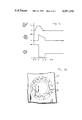
- FIG. 4 is a graph showing auxiliary coil current, main conduction current and main voltage vs. time during on-switching of the crossed-field switch device by on-switching the auxiliary magnetic field coil and off-switching by bringing the main magnetic field below the critical value.
- FIG. 5 is a graph of V vs. B for fixed pd and particular gas pressure showing the various operating points of the switch device during turn-on.
- Crossed-field switch device 10 is illustrated in FIG. 1. It has anode 12 and cathode 14. Cathode 14 may form the outer physical structure of the crossed-field switch device and act as the vacuum envelope. Interelectrode space 16, see FIG. 2, has a radial interelectrode distance d and is filled with an appropriate gas at appropriate pressure. Main field coil 18 provides a magnetic field in the active area of the interelectrode space, that is the area generally covered by the area of the main field coil. Insulator tower 20 connects power line 22 to anode 12 while line 24 is connected to the cathode. A source of electric power can be connected to these lines so that it can be off-switched. In the present case, the power source is represented by charged capacitor 26 with its series resistance 28.
- a capacitor with a series current control resistor provides an adequate pulse.
- capacitor 26 was charged to 100 kilovolts and resistor 28 was 550 ohms.
- main field coil 18 providing 100 gauss in the effective area of the interelectrode space, conduction does not occur because the operating point is above the toe of the voltage vs. magnetic field strength curve at point A in FIG. 5.
- Ionization source 30, comprised of five millicuries of cesium 137 as a gamma and beta ray source provides initial ionization, but cascading breakdown of the gas in the interelectrode space does not occur because the electron path length is too short in the high potential field provided by the interelectrode voltage. The electrons are attracted to the anode before they statistically cause sufficient collisions for cascading ionizing breakdown.
- the crossed-field switch device is in a non-conductive condition even with the main magnetic field on.
- Auxiliary magnetic field coil 32 is an ignition coil for igniting glow mode discharge in a localized area in the crossed-field switch device 10 when the crossed-field switch device has an applied voltage.
- the ignition magnetic field coil 32 is a 100 turn coil with 31/2 inch diameter. It is supplied from capacitor 34 of 25 microfarad capacity and the capacitor is connected to the auxiliary magnetic field coil 32 through on-switching ignitron 36. Thus, when ignitron 36 is turned on, the capacitor 34 discharges through coil 32. The charge is sufficient to produce a local annular field under the coil in the interelectrode space of sufficient strength to place the local region of the interelectrode space under the coil at an operating point within the conduction region.
- the magnetic field strength due to the auxiliary coil was approximately 1 kilogauss.
- the direction of the magnetic field resulting from this coil is schematically illustrated by field lines 38 in FIG. 3a.
- the auxiliary magnetic field coil is turned on so that there is an ignition magnetic field in the interelectrode space, then the electron trajectories become elongated.
- Electron trajectories 40 are illustrated in FIG. 3b as an illustration of the generally circular path they take under the influence of the ignition magnetic field.
- the magnetic field is sufficiently strong to move the operating point in the localized area to point B in FIG. 5 to make the electron paths sufficiently long to cause sufficient ionizing collisions for cascading breakdown.
- FIG. 4 illustrates an on-switching sequence.
- 100 kilovolts is applied to the electrodes.
- Main magnetic field coil 18 is on providing a main magnetic field in the effective interelectrode space of about 100 gauss with operating point at point A.
- the crossed-field switch device is nonconductive because these operating conditions are outside of the conductive region.
- time t 1 on switching ignitron 36 is turned on to permit capacitor 34 to discharge through auxiliary field coil 32 to provide the ignition magnetic field.
- the local operating point is moving from point A to point B. As seen in the top curve of FIG.
- the auxiliary coil current rises and when the current reached about 100 amperes at time t 2 about 200 microseconds later, the ignition magnetic field coil was sufficiently high, at least 1 kilogauss, to move the local operating point into the conductive region and cause a local glow mode discharge under the auxiliary magnetic field coil.
- This glow mode discharge reduces the main interelectrode voltage, see the bottom curve in FIG. 4, to point C.
- the auxiliary coil current pulse expires at t 3 but the operating conditions remain in the conductive region and the device conducts as the operating point moves to point D, see the main conduction current in the middle curve of FIG. 4.
- the magnetic field may be made to reach the needed strength in a small volume with much less energy.
- the coil need not encircle the tube diameter and may be placed anywhere on the cathode wall.
- the coil need not have any special symmetry. Its shape and positioning need only be such that a closed electron path is produced in the interelectrode space in a position where the coil can produce ignition magnetic field strengths, for example, in the order of 1 kiloguass.
Landscapes
- Gas-Filled Discharge Tubes (AREA)
- High-Tension Arc-Extinguishing Switches Without Spraying Means (AREA)
- Ignition Installations For Internal Combustion Engines (AREA)
- Manufacture Of Electron Tubes, Discharge Lamp Vessels, Lead-In Wires, And The Like (AREA)
Priority Applications (6)
| Application Number | Priority Date | Filing Date | Title |
|---|---|---|---|
| US05/797,720 US4091310A (en) | 1977-05-17 | 1977-05-17 | Method and apparatus for on-switching in a crossed-field switch device against high voltage |
| CA302,118A CA1099775A (en) | 1977-05-17 | 1978-04-27 | Method and apparatus for on-switching in a crossed- field switch device against high voltage |
| DE2819111A DE2819111C2 (de) | 1977-05-17 | 1978-04-29 | Verfahren zum Einschalten einer Gasentladungs-Schaltröhre mit gekreuzten Feldern und zur Durchführung dieses Verfahrens ausgebildete Schaltröhre |
| GB18677/78A GB1594918A (en) | 1977-05-17 | 1978-05-10 | Method and apparatus for on-switching in a crossed-field switch device against high voltage |
| FR7814472A FR2391552A1 (fr) | 1977-05-17 | 1978-05-16 | Procede et appareil de mise a l'etat conducteur d'un dispositif de commutation par application d'un champ magnetique auxiliaire |
| JP53057714A JPS5811065B2 (ja) | 1977-05-17 | 1978-05-17 | 交叉磁場使用のスイッチ装置 |
Applications Claiming Priority (1)
| Application Number | Priority Date | Filing Date | Title |
|---|---|---|---|
| US05/797,720 US4091310A (en) | 1977-05-17 | 1977-05-17 | Method and apparatus for on-switching in a crossed-field switch device against high voltage |
Publications (1)
| Publication Number | Publication Date |
|---|---|
| US4091310A true US4091310A (en) | 1978-05-23 |
Family
ID=25171625
Family Applications (1)
| Application Number | Title | Priority Date | Filing Date |
|---|---|---|---|
| US05/797,720 Expired - Lifetime US4091310A (en) | 1977-05-17 | 1977-05-17 | Method and apparatus for on-switching in a crossed-field switch device against high voltage |
Country Status (6)
| Country | Link |
|---|---|
| US (1) | US4091310A (de) |
| JP (1) | JPS5811065B2 (de) |
| CA (1) | CA1099775A (de) |
| DE (1) | DE2819111C2 (de) |
| FR (1) | FR2391552A1 (de) |
| GB (1) | GB1594918A (de) |
Cited By (5)
| Publication number | Priority date | Publication date | Assignee | Title |
|---|---|---|---|---|
| FR2458888A1 (fr) * | 1979-06-04 | 1981-01-02 | Hughes Aircraft Co | Dispositif a decharge electronique a champs croises |
| US4322661A (en) * | 1979-12-26 | 1982-03-30 | Huges Aircraft Company | Cross-field plasma mode electric conduction control device |
| US5008798A (en) * | 1989-12-21 | 1991-04-16 | Hughes Aircraft Company | Compact high voltage power supply |
| US5151663A (en) * | 1989-12-21 | 1992-09-29 | Hughes Aircraft Company | Plasma switch devices |
| US20040062659A1 (en) * | 2002-07-12 | 2004-04-01 | Sinha Mahadeva P. | Ion pump with combined housing and cathode |
Families Citing this family (2)
| Publication number | Priority date | Publication date | Assignee | Title |
|---|---|---|---|---|
| AT398459B (de) * | 1993-04-05 | 1994-12-27 | Forster Franz Ing Gmbh | Klemme |
| JP3075024B2 (ja) * | 1993-07-28 | 2000-08-07 | 富士電機株式会社 | 電磁波駆動型スイッチ |
Citations (2)
| Publication number | Priority date | Publication date | Assignee | Title |
|---|---|---|---|---|
| US3226591A (en) * | 1962-06-06 | 1965-12-28 | Aerospace Corp | Heavy duty gas tube with a magnetic trigger |
| US3890520A (en) * | 1974-09-23 | 1975-06-17 | Hughes Aircraft Co | Continuous electron injector for crossed-field switch tubes |
Family Cites Families (9)
| Publication number | Priority date | Publication date | Assignee | Title |
|---|---|---|---|---|
| NL50267C (de) * | 1936-05-07 | |||
| US3558960A (en) * | 1968-11-27 | 1971-01-26 | Hughes Aircraft Co | Switching device |
| US3604977A (en) * | 1969-01-15 | 1971-09-14 | Hughes Aircraft Co | A cross field switching device with a slotted electrode |
| US3641384A (en) * | 1970-03-16 | 1972-02-08 | Hughes Aircraft Co | Switching device |
| US3638061A (en) * | 1970-07-15 | 1972-01-25 | Hughes Aircraft Co | Magnetically controlled crossed-field interrupter and switch tube with pressure control for long duration pules |
| US3714510A (en) * | 1971-03-09 | 1973-01-30 | Hughes Aircraft Co | Method and apparatus for ignition of crossed field switching device for use in a hvdc circuit breaker |
| US3678289A (en) * | 1971-08-18 | 1972-07-18 | Hughes Aircraft Co | Magnetic field control circuit for crossed field switching devices |
| US3769537A (en) * | 1972-09-14 | 1973-10-30 | Hughes Aircraft Co | Baffle for perforated electrode in a crossed-field switch device |
| US3963960A (en) * | 1974-09-18 | 1976-06-15 | Hughes Aircraft Company | Bipolar crossed-field switch tube and circuit |
-
1977
- 1977-05-17 US US05/797,720 patent/US4091310A/en not_active Expired - Lifetime
-
1978
- 1978-04-27 CA CA302,118A patent/CA1099775A/en not_active Expired
- 1978-04-29 DE DE2819111A patent/DE2819111C2/de not_active Expired
- 1978-05-10 GB GB18677/78A patent/GB1594918A/en not_active Expired
- 1978-05-16 FR FR7814472A patent/FR2391552A1/fr active Granted
- 1978-05-17 JP JP53057714A patent/JPS5811065B2/ja not_active Expired
Patent Citations (2)
| Publication number | Priority date | Publication date | Assignee | Title |
|---|---|---|---|---|
| US3226591A (en) * | 1962-06-06 | 1965-12-28 | Aerospace Corp | Heavy duty gas tube with a magnetic trigger |
| US3890520A (en) * | 1974-09-23 | 1975-06-17 | Hughes Aircraft Co | Continuous electron injector for crossed-field switch tubes |
Cited By (6)
| Publication number | Priority date | Publication date | Assignee | Title |
|---|---|---|---|---|
| FR2458888A1 (fr) * | 1979-06-04 | 1981-01-02 | Hughes Aircraft Co | Dispositif a decharge electronique a champs croises |
| US4247804A (en) * | 1979-06-04 | 1981-01-27 | Hughes Aircraft Company | Cold cathode discharge device with grid control |
| US4322661A (en) * | 1979-12-26 | 1982-03-30 | Huges Aircraft Company | Cross-field plasma mode electric conduction control device |
| US5008798A (en) * | 1989-12-21 | 1991-04-16 | Hughes Aircraft Company | Compact high voltage power supply |
| US5151663A (en) * | 1989-12-21 | 1992-09-29 | Hughes Aircraft Company | Plasma switch devices |
| US20040062659A1 (en) * | 2002-07-12 | 2004-04-01 | Sinha Mahadeva P. | Ion pump with combined housing and cathode |
Also Published As
| Publication number | Publication date |
|---|---|
| FR2391552B1 (de) | 1983-02-04 |
| DE2819111A1 (de) | 1978-11-23 |
| JPS53142864A (en) | 1978-12-12 |
| DE2819111C2 (de) | 1983-03-03 |
| JPS5811065B2 (ja) | 1983-03-01 |
| GB1594918A (en) | 1981-08-05 |
| CA1099775A (en) | 1981-04-21 |
| FR2391552A1 (fr) | 1978-12-15 |
Similar Documents
| Publication | Publication Date | Title |
|---|---|---|
| US2146025A (en) | Coating by cathode disintegration | |
| US3104345A (en) | Plasma generator for a highly ionized electrical plasma | |
| US4091310A (en) | Method and apparatus for on-switching in a crossed-field switch device against high voltage | |
| US2856532A (en) | Pulsed ion source | |
| US3949260A (en) | Continuous ionization injector for low pressure gas discharge device | |
| US2883580A (en) | Pulsed ion source | |
| US4322661A (en) | Cross-field plasma mode electric conduction control device | |
| US4034260A (en) | Gridded crossed-field tube and ignition method | |
| US4034261A (en) | Gridded crossed-field tube | |
| US1863702A (en) | Gaseous conduction method and apparatus | |
| US2504231A (en) | Gaseous discharge device | |
| US3639849A (en) | Apparatus for producing a highly concentrated beam of electrons | |
| US3510713A (en) | Method of and appparatus for producing a highly concentrated beam of electrons | |
| US3087091A (en) | Spark gap switch | |
| US3678289A (en) | Magnetic field control circuit for crossed field switching devices | |
| US3636407A (en) | Gas-discharge device with magnetic means for extinguishing the discharge | |
| US2409716A (en) | High-voltage discharge device | |
| US3736038A (en) | Spot-knocking method for electronic tubes | |
| US2124682A (en) | Electrical gaseous discharge device | |
| US3610989A (en) | Production and utilization of high-density plasma | |
| US3651365A (en) | Xenon slash lamp with sodium starting band and method of making same | |
| US2813992A (en) | Gas discharge device utilizing controlled electron trapping | |
| US3890520A (en) | Continuous electron injector for crossed-field switch tubes | |
| US3137820A (en) | High-current pulsed ion source | |
| US4071801A (en) | Crossed-field switch device and method for off-switching |