US4079806A - Vehicle starting circuit to by-pass auxiliary steering system - Google Patents
Vehicle starting circuit to by-pass auxiliary steering system Download PDFInfo
- Publication number
- US4079806A US4079806A US05/751,378 US75137876A US4079806A US 4079806 A US4079806 A US 4079806A US 75137876 A US75137876 A US 75137876A US 4079806 A US4079806 A US 4079806A
- Authority
- US
- United States
- Prior art keywords
- vehicle
- pump
- auxiliary
- driven
- vehicle battery
- Prior art date
- Legal status (The legal status is an assumption and is not a legal conclusion. Google has not performed a legal analysis and makes no representation as to the accuracy of the status listed.)
- Expired - Lifetime
Links
- 239000012530 fluid Substances 0.000 claims description 40
- 230000008878 coupling Effects 0.000 claims description 11
- 238000010168 coupling process Methods 0.000 claims description 11
- 238000005859 coupling reaction Methods 0.000 claims description 11
- 230000007935 neutral effect Effects 0.000 claims description 11
- 238000004804 winding Methods 0.000 claims 2
- 238000005086 pumping Methods 0.000 description 10
- 239000004020 conductor Substances 0.000 description 4
- 230000000694 effects Effects 0.000 description 3
- 230000007246 mechanism Effects 0.000 description 3
- 230000005540 biological transmission Effects 0.000 description 1
- 230000001143 conditioned effect Effects 0.000 description 1
- 238000010276 construction Methods 0.000 description 1
- 238000010586 diagram Methods 0.000 description 1
- 230000007257 malfunction Effects 0.000 description 1
- 239000000463 material Substances 0.000 description 1
- 230000004048 modification Effects 0.000 description 1
- 238000012986 modification Methods 0.000 description 1
- 239000007858 starting material Substances 0.000 description 1
Images
Classifications
-
- B—PERFORMING OPERATIONS; TRANSPORTING
- B62—LAND VEHICLES FOR TRAVELLING OTHERWISE THAN ON RAILS
- B62D—MOTOR VEHICLES; TRAILERS
- B62D5/00—Power-assisted or power-driven steering
- B62D5/06—Power-assisted or power-driven steering fluid, i.e. using a pressurised fluid for most or all the force required for steering a vehicle
Definitions
- This invention relates in general to vehicle ignition systems and, in particular, to ignition systems for vehicles having an auxiliary or emergency steering system which is actuated upon engine failure during operation of the vehicle.
- this invention relates to a vehicle ignition circuit which electrically isolates an auxiliary steering system during vehicle starting to eliminate drain on the vehicle battery.
- the hydraulic fluid required for power steering and power brakes is normally provided by a hydraulic pump driven by the vehicle engine to supply the power steering and brake units, as well as to operate hydraulically powered auxiliary equipment such as dozer or grader blades depending upon the particular type of equipment utilized with the vehicle.
- a hydraulic pump driven by the vehicle engine to supply the power steering and brake units, as well as to operate hydraulically powered auxiliary equipment such as dozer or grader blades depending upon the particular type of equipment utilized with the vehicle.
- the hydraulic pump supplying fluid to these components is no longer operated by the engine and, therefore, the loss of pressurized hydraulic fluid results in the loss of steering and brakes.
- auxiliary or emergency hydraulic pumping systems are incorporated in such vehicles.
- Such systems usually include an electrically driven motor and pump unit, powered from the vehicle batteries, to provide hydraulic fluid under pressure to the vehicle brake and steering systems in the event the engine or the engine-driven main hydraulic pump is inoperative for any reason.
- One such auxiliary system is disclosed in U.S. Pat. No. 3,153,462, which describes an electrically powered auxiliary or emergency steering system manually actuated by the machine operator upon the occurrence of an emergency condition or the failure of the engine during operation.
- U.S. Pat. No. 3,153,462 describes an electrically powered auxiliary or emergency steering system manually actuated by the machine operator upon the occurrence of an emergency condition or the failure of the engine during operation.
- it may be too late to energize the auxiliary system in time to avoid an accident.
- auxiliary or emergency pumping systems creates a problem.
- the engine is not running. This lack of hydraulic fluid pressure in the lines is detected by the sensors of the auxiliary or emergency pumping system as an engine failure. Therefore, the auxiliary system is coupled into the vehicle ignition circuit to provide steering and/or braking which are not needed at that time.
- the resultant coupling of the auxiliary pumping or emergency steering system during engine startup adds drain to the vehicle batteries diverting power frequently required to start the engine.
- U.S. Pat. No. 3,921,7408 wherein a logic system of relays is provided in a vehicle ignition system.
- the disclosed logic system places the emergency pumping system into a condition for actuation only after the engine has been in operation. After being conditioned for actuation, in the event of engine failure, the emergency pumping system will be coupled into the electrical circuitry to actuate a pump to effect steering and braking.
- the emergency or auxiliary pumping system is removed from the ignition circuit and is not in condition to operate untilsuch time as the engine is restarted to place it in a proper condition to be actuated.
- Another object of this invention is to electrically isolate an auxiliary or emergency pumping system during engine startup through a minimum of electrical components to increase system reliability.
- an electric circuit for use in the ignition system of a vehicle having an auxiliary hydraulic fluid pumping system powered by the vehicle battery and energized upon engine failure or shutdown during vehicle operation to disconnect the auxiliary system from the battery during engine starting.
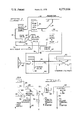
- FIG. 1 is a hydraulic schematic of a vehicle hydraulic system for steering a vehicle and providing hydraulic fluid to operate auxiliary equipment;
- FIG. 2 is an electrical schematic diagram of a portion of the vehicle ignition system to better illustrate the manner in which the auxiliary electric motor and pump are coupled into the system for an emergency while being electrically isolated during engine startup.
- FIG. 1 there is shown a typical hydraulic system for a vehicle of the type previously discussed which includes a main hydraulic pump 10 used to effect steering of the vehicle and a hydraulic pump 22 for supplying pressurized fluid to auxiliary equipment used with the vehicle such as dozer blades or loading buckets.
- Both the hydraulic pumps 10 and 22 are driven by the vehicle engine (not shown) and are connected to a hydraulic fluid reservoir 12 through conduits 14 and 24, respectively.
- the output from the main steering pump 10 and the auxiliary equipment pump 22 are connected to a demand valve 30 by means of conduits 16 and 26, respectively.
- the demand valve 30 controls a flow of the hydraulic fluid to the steering system through a conduit 36 or to the auxiliary equipment through a conduit 34.
- the demand valve 30 functions to control the flow of hydraulic fluid such that the steering system is given priority over the auxiliary equipment to insure that sufficient hydraulic fluid is provided for steering purposes at all times.
- a sensor valve 20 is coupled between the main steering pump 10 and the demand valve 30. Hydraulic fluid pumped from the main steering pump 10 through the conduit 16 will pass through the sensor valve 20 then through a conduit 32 into the demand valve 30.
- the valve 20 may be of a type having a set of electrical contacts associated therewith that are sensitive either to pressure in the hydraulic system or flow of hydraulic fluid. While the valve 20 is illustrated as being sensitive to fluid flow, both the pressure sensitive or flow sensitive type are suitable such as described in the afore-mentioned patents.
- the main steering pump 10 will supply pressurized fluid flow through the sensor valve 20 to the demand valve 30. Hydraulic fluid passing through the valve 20 will maintain the associated electrical contacts open isolating the auxiliary steering system from operation. In the event the vehicle engine fails or for any other reason the main steering pump 10 does not function to provide a sufficient quantity of hydraulic fluid to the sensor valve 20, the valve will close the associateed electrical contacts illustrated by a pair of switch contacts 20A in FIG. 2.
- the switch contacts 20A illustrate the interface between the hydraulic circuit of FIG. 1 and the electrical circuit of FIG. 2.
- hydraulic fluid passing through the demand valve 30 is supplied to a steering valve 40 through the conduit 36 and to auxiliary equipment (not shown) through the conduit 34.
- the steering valve 40 is connected to a manually operated steering mechanism 46 for actuating a pair of steering cylinders 52 and 54 coupled to the steering valve 40 through conduits 48 and 50, respectively, to steer the vehicle.
- the hydraulic fluid passing through the steering valve 40 is then returned to the reservoir 12 through a conduit 44.
- a pressure relief valve 38 is coupled between conduits 36 and 44 to by-pass the steering valve 40 in the event the hydraulic fluid pressure is above a predetermined level.
- an electrically operated motor and pump 60 is provided in the hydraulic circuit.
- the auxiliary or emergency pump and motor 60 is coupled to the reservoir 12 through conduits 24 and 56 and to the demand valve 30 through a conduit 58, the sensor valve 20 and the conduit 32.
- the motor and pump 60 supplying hydraulic fluid to the demand valve 30 will insure that the steering system is provided with sufficient hydraulic fluid in the event the electric motor 60 is actuated.
- normally open sensor valve 20 will effect closing of the electrical contacts of the pressure or flow sensitive switch associated therewith and illustrated at 20A. Closing of the contacts 20A completes a circuit from the vehicle battery (not shown) through a vehicle key switch (not shown), conductors 62, 64 and 66, normally closed contacts of a cut-out relay 68, conductor 70 and through a coil of a relay 72 to ground. At the same time a warning light and/or buzzer 76 is energized through conductor 74 to provide a warning signal to the machine operator that the engine and/or main steering pump has failed.
- the electrical contacts 20A associated with sensor valve 20 are closed whenever there is an insufficient flow of hydraulic fluid from conduit 16 through the sensor valve 20.
- sensor valve 20 During engine startup the absence of sufficient hydraulic fluid flow would be interpreted by sensor valve 20 as an engine or main pump failure thereby coupling the electric motor and pump into the electrical system providing a drain on the vehicle battery when starting. Therefore, when the transmission of the vehicle is placed in neutral, which is required for starting, contacts of a neutral start switch 90 are closed providing a circuit through conductors 62, contacts 90 and lead 92 to a vehicle starter solenoid (not shown) for starting the engine. The closing of the contacts 90 complete a circuit with a lead 88 connected to the coil of the cut-out relay 68 to open the normally closed contacts of cut-out relay 68 electrically isolating the electric motor and pump and the warning device 76 from the circuit.
- the contacts 20A of the sensor valve 20 control energizing of the electric motor and pump 60 to insure that an emergency steering system is provided at all times.
- the normally closed contacts of cut-out relay 68 will open to electrically isolate the electric motor and pump 60 and warning device 76 from the system preventing excessive drain on the battery during startup.
Landscapes
- Engineering & Computer Science (AREA)
- Chemical & Material Sciences (AREA)
- Combustion & Propulsion (AREA)
- Transportation (AREA)
- Mechanical Engineering (AREA)
- Power Steering Mechanism (AREA)
- Air Bags (AREA)
- Control Of Vehicle Engines Or Engines For Specific Uses (AREA)
Priority Applications (9)
| Application Number | Priority Date | Filing Date | Title |
|---|---|---|---|
| US05/751,378 US4079806A (en) | 1976-12-17 | 1976-12-17 | Vehicle starting circuit to by-pass auxiliary steering system |
| CA285,148A CA1078046A (en) | 1976-12-17 | 1977-08-17 | Vehicle starting circuit to by-pass auxiliary steering system |
| GB36740/77A GB1584688A (en) | 1976-12-17 | 1977-09-02 | Vehicle starting circuit to by-pass auxilliary steering system |
| DE19772741628 DE2741628A1 (de) | 1976-12-17 | 1977-09-15 | Fahrzeuganlasschaltung mit umgehung von hilfssteuersystemen |
| IT27645/77A IT1085982B (it) | 1976-12-17 | 1977-09-16 | Circuito di avviamento di autoveicoli per bipassare un sistema di servosterzo ausiliare |
| FR7729116A FR2374197A1 (fr) | 1976-12-17 | 1977-09-28 | Appareil d'isolement d'un systeme de direction auxiliaire d'un vehicule lors du demarrage |
| BR7706508A BR7706508A (pt) | 1976-12-17 | 1977-09-29 | Aperfeicoamento em circuito de partida para veiculo |
| JP13069277A JPS5378532A (en) | 1976-12-17 | 1977-10-31 | Vehicle starting circuit for detouring auxiliary steering system |
| SE7714308A SE7714308L (sv) | 1976-12-17 | 1977-12-15 | Startkrets for fordon |
Applications Claiming Priority (1)
| Application Number | Priority Date | Filing Date | Title |
|---|---|---|---|
| US05/751,378 US4079806A (en) | 1976-12-17 | 1976-12-17 | Vehicle starting circuit to by-pass auxiliary steering system |
Publications (1)
| Publication Number | Publication Date |
|---|---|
| US4079806A true US4079806A (en) | 1978-03-21 |
Family
ID=25021718
Family Applications (1)
| Application Number | Title | Priority Date | Filing Date |
|---|---|---|---|
| US05/751,378 Expired - Lifetime US4079806A (en) | 1976-12-17 | 1976-12-17 | Vehicle starting circuit to by-pass auxiliary steering system |
Country Status (9)
| Country | Link |
|---|---|
| US (1) | US4079806A (enExample) |
| JP (1) | JPS5378532A (enExample) |
| BR (1) | BR7706508A (enExample) |
| CA (1) | CA1078046A (enExample) |
| DE (1) | DE2741628A1 (enExample) |
| FR (1) | FR2374197A1 (enExample) |
| GB (1) | GB1584688A (enExample) |
| IT (1) | IT1085982B (enExample) |
| SE (1) | SE7714308L (enExample) |
Cited By (6)
| Publication number | Priority date | Publication date | Assignee | Title |
|---|---|---|---|---|
| FR2472501A1 (fr) * | 1979-12-26 | 1981-07-03 | Deere & Co | Dispositif pour la commande d'un systeme de servo-direction hydraulique pour vehicule automobile |
| US4410057A (en) * | 1980-05-09 | 1983-10-18 | Clark Equipment Company | Emergency hydraulic system |
| GB2160162A (en) * | 1984-06-13 | 1985-12-18 | Steering Developments Ltd | Hydraulic steering system |
| US6463949B2 (en) | 2000-12-08 | 2002-10-15 | Caterpillar Inc. | Method and apparatus for determining a valve status |
| US20110146261A1 (en) * | 2009-12-23 | 2011-06-23 | Caterpillar Inc. | System and method for controlling an electro-hydraulic charging system |
| KR20220042205A (ko) * | 2019-09-04 | 2022-04-04 | 가부시키가이샤 도요다 지도숏키 | 산업 차량의 엔진 제어 장치 |
Citations (6)
| Publication number | Priority date | Publication date | Assignee | Title |
|---|---|---|---|---|
| US3083533A (en) * | 1960-10-24 | 1963-04-02 | Clark Equipment Co | Hydraulic system |
| US3434282A (en) * | 1967-03-14 | 1969-03-25 | Dura Corp | Safety backup system for power steering |
| US3558239A (en) * | 1969-06-25 | 1971-01-26 | Borg Warner | Power steering back-up pressure system |
| US3762492A (en) * | 1970-05-04 | 1973-10-02 | B Ron | Dual fluid supply circuit for a power steering and a hydraulic power brake |
| US3921748A (en) * | 1974-10-24 | 1975-11-25 | Case Co J I | Vehicle power steering electric circuit |
| US3940931A (en) * | 1975-01-17 | 1976-03-02 | Caterpillar Tractor Co. | Automatic control circuit for an electrically powered hydraulic pump |
-
1976
- 1976-12-17 US US05/751,378 patent/US4079806A/en not_active Expired - Lifetime
-
1977
- 1977-08-17 CA CA285,148A patent/CA1078046A/en not_active Expired
- 1977-09-02 GB GB36740/77A patent/GB1584688A/en not_active Expired
- 1977-09-15 DE DE19772741628 patent/DE2741628A1/de not_active Withdrawn
- 1977-09-16 IT IT27645/77A patent/IT1085982B/it active
- 1977-09-28 FR FR7729116A patent/FR2374197A1/fr active Granted
- 1977-09-29 BR BR7706508A patent/BR7706508A/pt unknown
- 1977-10-31 JP JP13069277A patent/JPS5378532A/ja active Pending
- 1977-12-15 SE SE7714308A patent/SE7714308L/ unknown
Patent Citations (6)
| Publication number | Priority date | Publication date | Assignee | Title |
|---|---|---|---|---|
| US3083533A (en) * | 1960-10-24 | 1963-04-02 | Clark Equipment Co | Hydraulic system |
| US3434282A (en) * | 1967-03-14 | 1969-03-25 | Dura Corp | Safety backup system for power steering |
| US3558239A (en) * | 1969-06-25 | 1971-01-26 | Borg Warner | Power steering back-up pressure system |
| US3762492A (en) * | 1970-05-04 | 1973-10-02 | B Ron | Dual fluid supply circuit for a power steering and a hydraulic power brake |
| US3921748A (en) * | 1974-10-24 | 1975-11-25 | Case Co J I | Vehicle power steering electric circuit |
| US3940931A (en) * | 1975-01-17 | 1976-03-02 | Caterpillar Tractor Co. | Automatic control circuit for an electrically powered hydraulic pump |
Cited By (14)
| Publication number | Priority date | Publication date | Assignee | Title |
|---|---|---|---|---|
| FR2472501A1 (fr) * | 1979-12-26 | 1981-07-03 | Deere & Co | Dispositif pour la commande d'un systeme de servo-direction hydraulique pour vehicule automobile |
| US4345660A (en) * | 1979-12-26 | 1982-08-24 | Deere & Company | Vehicle emergency steering system |
| US4410057A (en) * | 1980-05-09 | 1983-10-18 | Clark Equipment Company | Emergency hydraulic system |
| GB2160162A (en) * | 1984-06-13 | 1985-12-18 | Steering Developments Ltd | Hydraulic steering system |
| EP0165758A3 (en) * | 1984-06-13 | 1987-01-07 | Steering Dev Ltd | Hydraulic power steering systems for motor vehicles |
| US6463949B2 (en) | 2000-12-08 | 2002-10-15 | Caterpillar Inc. | Method and apparatus for determining a valve status |
| US20110146261A1 (en) * | 2009-12-23 | 2011-06-23 | Caterpillar Inc. | System and method for controlling an electro-hydraulic charging system |
| US8844278B2 (en) | 2009-12-23 | 2014-09-30 | Caterpillar Inc. | System and method for controlling an electro-hydraulic charging system |
| KR20220042205A (ko) * | 2019-09-04 | 2022-04-04 | 가부시키가이샤 도요다 지도숏키 | 산업 차량의 엔진 제어 장치 |
| CN114303008A (zh) * | 2019-09-04 | 2022-04-08 | 株式会社丰田自动织机 | 工业车辆的发动机控制装置 |
| US20220298981A1 (en) * | 2019-09-04 | 2022-09-22 | Kabushiki Kaisha Toyota Jidoshokki | Engine control device of industrial vehicle |
| CN114303008B (zh) * | 2019-09-04 | 2024-01-02 | 株式会社丰田自动织机 | 工业车辆的发动机控制装置 |
| AU2020341409B2 (en) * | 2019-09-04 | 2024-01-18 | Kabushiki Kaisha Toyota Jidoshokki | Engine control device for industrial vehicle |
| US12460591B2 (en) * | 2019-09-04 | 2025-11-04 | Kabushiki Kaisha Toyota Jidoshokki | Engine control device of industrial vehicle |
Also Published As
| Publication number | Publication date |
|---|---|
| BR7706508A (pt) | 1978-07-04 |
| FR2374197B3 (enExample) | 1980-06-06 |
| FR2374197A1 (fr) | 1978-07-13 |
| DE2741628A1 (de) | 1978-06-22 |
| SE7714308L (sv) | 1978-06-18 |
| JPS5378532A (en) | 1978-07-12 |
| CA1078046A (en) | 1980-05-20 |
| GB1584688A (en) | 1981-02-18 |
| IT1085982B (it) | 1985-05-28 |
Similar Documents
| Publication | Publication Date | Title |
|---|---|---|
| US3940931A (en) | Automatic control circuit for an electrically powered hydraulic pump | |
| US4410057A (en) | Emergency hydraulic system | |
| KR0156433B1 (ko) | 전유압조향시스템의 비상조향장치 | |
| US4338896A (en) | Fire suppression system | |
| US4339154A (en) | Vehicle brake system | |
| US3820620A (en) | Vehicle power steering electrohydraulic safety backup system | |
| CA1148479A (en) | Vehicle emergency steering system | |
| US4632079A (en) | Device for automatically restarting the engine of a motor-vehicle after sudden braking | |
| US4317499A (en) | Vehicle emergency steering system | |
| US4079806A (en) | Vehicle starting circuit to by-pass auxiliary steering system | |
| US3582150A (en) | Brake system | |
| US2954671A (en) | Power steering means | |
| US4136752A (en) | Vehicle brake control system | |
| US5066073A (en) | Brake system for automotive vehicles | |
| US4129001A (en) | Engine air heater and starting circuits to by-pass auxiliary steering circuit | |
| GB1591206A (en) | Hydraulic steering system | |
| KR101298401B1 (ko) | 휠로더의 자가진단 비상 조향장치 | |
| US3921748A (en) | Vehicle power steering electric circuit | |
| US4802710A (en) | Electric switching device | |
| EP0036071A1 (en) | Fire suppression system | |
| US4015681A (en) | Ground driven hydraulic emergency steering system | |
| US4220050A (en) | Control system actuating assembly | |
| EP0165758B1 (en) | Hydraulic power steering systems for motor vehicles | |
| KR0167975B1 (ko) | 비상용 브레이크 장치 | |
| US2629085A (en) | Safety control and signal system for motor vehicles |
Legal Events
| Date | Code | Title | Description |
|---|---|---|---|
| AS | Assignment |
Owner name: FIATALLIS S.P.A, ZONA INDUSTRIALE SURBO, I-73014 L Free format text: ASSIGNMENT OF ASSIGNORS INTEREST.;ASSIGNOR:FIATALLIS NORTH AMERICA, INC.;REEL/FRAME:004390/0121 Effective date: 19850206 |