US40586A - Improved machine for twisting wires for marking-tags - Google Patents
Improved machine for twisting wires for marking-tags Download PDFInfo
- Publication number
- US40586A US40586A US40586DA US40586A US 40586 A US40586 A US 40586A US 40586D A US40586D A US 40586DA US 40586 A US40586 A US 40586A
- Authority
- US
- United States
- Prior art keywords
- shaft
- tenon
- tags
- marking
- wire
- Prior art date
- Legal status (The legal status is an assumption and is not a legal conclusion. Google has not performed a legal analysis and makes no representation as to the accuracy of the status listed.)
- Expired - Lifetime
Links
- 239000002184 metal Substances 0.000 description 2
- 235000013290 Sagittaria latifolia Nutrition 0.000 description 1
- 235000015246 common arrowhead Nutrition 0.000 description 1
- 238000010276 construction Methods 0.000 description 1
- 235000020004 porter Nutrition 0.000 description 1
- 230000000630 rising effect Effects 0.000 description 1
- 238000004904 shortening Methods 0.000 description 1
Images

Classifications
-
- B—PERFORMING OPERATIONS; TRANSPORTING
- B21—MECHANICAL METAL-WORKING WITHOUT ESSENTIALLY REMOVING MATERIAL; PUNCHING METAL
- B21F—WORKING OR PROCESSING OF METAL WIRE
- B21F7/00—Twisting wire; Twisting wire together
Definitions
- the obj ect ofmynvention is to produce a machine which will facilitate the twisting of the wires attached to tags for marking bales of merchandise, orofwires used for any purpose which require to be twisted in asimilar manner.
- A represents a table, having attached to its upper surface three double upright standards, B O D, of the form shown in the drawings or of any other desirable form,for thepurpose of supporting the various parts of the machinery.
- E represents a cog-wheel supported by the standard B, and working in and actuating the smaller cog-wheel f. These wheels are put in motion by a power applied at g, which may be hand-power, as in the model from which these drawings are made, or any other power.
- the shaft a of the wheel fis perforated with a small rectangular aperture, t', and a portion of the metal surrounding one end of the aperture and extending therefrom to the end ofthe shaft is removed, leaving, however, a double tenon, K, rising in the center ofthe part from which such removal is made, extending from the-aperturez' to the end of the shaft, standing in the same plane with the aperture/i and perpendicular to the plane of the face of the metal left after the removal of the portion referred to.
- This tenon mayproject beyond the end of the main body ofthe shaft,'as shown in the drawings.
- the end of the tenon at the aperturet' is to be made perpendicular to the axis of the shaft.
- the shafts of both wheels E and f areheld in position by shoulders, as shown e and f', and pins, as shown at e and f, or their equivalents.
- C represents a double standard similar-to that just described, supporting a sliding shaft, Z, the end of which toward the centerof the machine is formed into a tenon similar to that upon the end of the shaft of the wheel f, except that itis not perforated as that is at fi.
- This shaft has a free longitudinal motion in its socket in the standard O to such an extent that it may be slid outward from the center of the machine till the outer end of the tenon reaches the standard at m, and may be slid inward till the shoulder o bears against the standard at n.
- the shoulder o has a notch cut in each side of it to receive and hold the arms p p of the triangular lever q, and having the notches of greater width than the arms p p, in order that there may be no invterference with the freedom of their motion, which is in the arc of a circle having its center at r, where the tri angular lever is supported by a movable joint attached to the table.
- To the triangular lever at s is fastened a string or chain connected with a weight, t, and passing over a fixed pulley, a, to apedal, fu, to which it is also fastened.
- the double upright standards B and C stand in the same plane, and are so situated that a straightline passing longitudinally through the axis of the shaft Z, and sufficiently extended, would also pass longitudinally through the axis of the shaft u.
- the third upright, D stands in a plane perpendicular to that of the two others, and supports'a single shaft, w, in such a position that a straight line passing longitudinally through its axis would intersect and be perpendicular to a straight line passing from the axis of a to the axis of Z.
- the shaft w is held in its position by shoulders and, pins, or their equivalents, similar to those described in connection with the shafts e and a. It revolves on its axis by the application of power at x.
- At y is a small thumb-screw extending into the interior of the shaft, which is hollow like a gun-barrel, the end ofthe bore be ing shown at z, where it is slightly chambered or tunneled, so as to admit of anything being thrust into it more readily.
- the thumb-screw being unscrewed and the operator being supposed to hold in his hand a wire of the proper length, one end of which passes through a barb or arrow-head forfastening tags to bales and the other end through the tag itself, the machine is worked as follows: The operator thrusts both ends of the wire into thebarrel of the shaft w, and turns the thumb-screw till it holds them.
- the weight Upon removing the foot the weight causes the shaft to pull upon the wire, and thus to straighten it out and hold it in position,while as it twists and shortens the weight rises an d allows the shaft to move inward and accommodate itself to the shortening ofthe wire.
- the shaft w a few revolutions, and the wire is rapidly twisted from the muzzle @toward him until all the surplus wire is twisted up and the rest extends in two straight lines parallel to each other and close together from tenon to tenon.
Landscapes
- Engineering & Computer Science (AREA)
- Mechanical Engineering (AREA)
- Adornments (AREA)
Description
llmrnn STATES PATENT Ormea MARTIAL DIMOOK, OF NEWARK, NEWl JERSEY, ASSIGN OR TO PORTER FITCH,
' OF BROOKLYN, NEW YORK.
IMPROVED MACHINE FOR TWlSTING WIRES FOR MARKING-TAGS.
Specification forming part of Letters Patent No. 40,586, dated November 10, 1863.
` To all whom it may concern.-
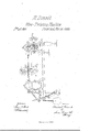
Be it known that I, MARTIAL DIMooK, of N ewarlgin the county of Essex and State of New Jersey, have invented a new and useful Improvement in Machines for Twistin g the Wires Attached to Marking-Tags;l and I do h ereby declare that the following is a full and exact description thereof, reference being had to the accompanying drawing, which represents a perspective view of my invention, and to the letters of reference marked thereon.
The obj ect ofmynvention is to produce a machine which will facilitate the twisting of the wires attached to tags for marking bales of merchandise, orofwires used for any purpose which require to be twisted in asimilar manner.
A represents a table, having attached to its upper surface three double upright standards, B O D, of the form shown in the drawings or of any other desirable form,for thepurpose of supporting the various parts of the machinery.
E represents a cog-wheel supported by the standard B, and working in and actuating the smaller cog-wheel f. These wheels are put in motion by a power applied at g, which may be hand-power, as in the model from which these drawings are made, or any other power. The shaft a of the wheel fis perforated with a small rectangular aperture, t', and a portion of the metal surrounding one end of the aperture and extending therefrom to the end ofthe shaft is removed, leaving, however, a double tenon, K, rising in the center ofthe part from which such removal is made, extending from the-aperturez' to the end of the shaft, standing in the same plane with the aperture/i and perpendicular to the plane of the face of the metal left after the removal of the portion referred to. This tenon mayproject beyond the end of the main body ofthe shaft,'as shown in the drawings. The end of the tenon at the aperturet' is to be made perpendicular to the axis of the shaft. The shafts of both wheels E and f areheld in position by shoulders, as shown e and f', and pins, as shown at e and f, or their equivalents.
C represents a double standard similar-to that just described, supporting a sliding shaft, Z, the end of which toward the centerof the machine is formed into a tenon similar to that upon the end of the shaft of the wheel f, except that itis not perforated as that is at fi. This shaft has a free longitudinal motion in its socket in the standard O to such an extent that it may be slid outward from the center of the machine till the outer end of the tenon reaches the standard at m, and may be slid inward till the shoulder o bears against the standard at n. The shoulder o has a notch cut in each side of it to receive and hold the arms p p of the triangular lever q, and having the notches of greater width than the arms p p, in order that there may be no invterference with the freedom of their motion, which is in the arc of a circle having its center at r, where the tri angular lever is supported by a movable joint attached to the table. To the triangular lever at s is fastened a string or chain connected with a weight, t, and passing over a fixed pulley, a, to apedal, fu, to which it is also fastened. The double upright standards B and C stand in the same plane, and are so situated that a straightline passing longitudinally through the axis of the shaft Z, and sufficiently extended, would also pass longitudinally through the axis of the shaft u. The third upright, D, stands in a plane perpendicular to that of the two others, and supports'a single shaft, w, in such a position that a straight line passing longitudinally through its axis would intersect and be perpendicular to a straight line passing from the axis of a to the axis of Z. The shaft w is held in its position by shoulders and, pins, or their equivalents, similar to those described in connection with the shafts e and a. It revolves on its axis by the application of power at x. At y is a small thumb-screw extending into the interior of the shaft, which is hollow like a gun-barrel, the end ofthe bore be ing shown at z, where it is slightly chambered or tunneled, so as to admit of anything being thrust into it more readily. The thumb-screw being unscrewed and the operator being supposed to hold in his hand a wire of the proper length, one end of which passes through a barb or arrow-head forfastening tags to bales and the other end through the tag itself, the machine is worked as follows: The operator thrusts both ends of the wire into thebarrel of the shaft w, and turns the thumb-screw till it holds them. He then seizes the tag in his left hand and the barb in his right, and, pulling them apart as far as the wire will permit, inserts the barb into the aperture t' in such a manner that the wire is made to pass around the whole length ofthe tenon k. At the same time he slips the opposite end of the doubled wire over the tenon lz, leaving the wire passing around the tenon. If, on account of the weight t the shaft l should be drawn back so as to render it difficult to pass the wire around the tenon h, the operator puts his foot on the pedal o, and by pressing it down lifts the weight t and allows the shaft Z to be easily slid inward to .receive'the-wire. Upon removing the foot the weight causes the shaft to pull upon the wire, and thus to straighten it out and hold it in position,while as it twists and shortens the weight rises an d allows the shaft to move inward and accommodate itself to the shortening ofthe wire. 'Ihe operator now gives the shaft w a few revolutions, and the wire is rapidly twisted from the muzzle @toward him until all the surplus wire is twisted up and the rest extends in two straight lines parallel to each other and close together from tenon to tenon. Unscrewing the thumb-screw,theliberated and shortened wire springs from its connement in the barrel, and by a few turns of the wh eel Eis twisted irmly and evenly from the inner end of one tenon to theinner end of the other, leaving a straight untwisted loop at each end where it passes around the tenons, and leaving the tag in one of theseloops and the barb in the other. It is removed from the machine by simply pulling the barb out of the aperture in which it had been held and is now ready for use.
I do Anot intend to limit myself to the use of' the thumb-screw y for the `purpose described, but may use in its place a spring or any equivalent; neither do I intend to confine myself to the use of the arrangement consisting of the triangular lever, the weight, and pedal for the purpose described, but vmay use any other device which will answer the purpose as well, nor yet to the cog-wheels E and f, but may use wheels and bands or any other equivalents.
`\Vhat I claim as my invention, and desire to secure by Letters Patent, is-
Y 1. The construction and use of the shaft a, having the aperturez' and the double tenon 7c, substantially as shown and described.
2. The constructionand use of thesliding shaft Z, having the double tenon h and the notches in the shoulder o, substantially as shown and described. 4
3. The arrangement'and use of the shaft a, having aperture z' and double tenon 7c, the sliding shaft ,with its double tenon h and notches inthe shoulder o, inoonnection and co-operation with each other and with the shaft w,when used for twisting wires, substantially as shown and described.
. MARTIAL DIMOGK.
Vitnesses:
R. SHEPARD, LYsANDER HILL.
Publications (1)
| Publication Number | Publication Date |
|---|---|
| US40586A true US40586A (en) | 1863-11-10 |
Family
ID=2110156
Family Applications (1)
| Application Number | Title | Priority Date | Filing Date |
|---|---|---|---|
| US40586D Expired - Lifetime US40586A (en) | Improved machine for twisting wires for marking-tags |
Country Status (1)
| Country | Link |
|---|---|
| US (1) | US40586A (en) |
-
0
- US US40586D patent/US40586A/en not_active Expired - Lifetime
Similar Documents
| Publication | Publication Date | Title |
|---|---|---|
| US40586A (en) | Improved machine for twisting wires for marking-tags | |
| US470545A (en) | Wire-bending pliers | |
| US209018A (en) | Improvement in needles | |
| US576244A (en) | Curling-iron | |
| US207449A (en) | Improvement in barb-winders | |
| US205094A (en) | Improvement in graining-tools | |
| US746139A (en) | Fence-weaving machine. | |
| US1436812A (en) | Rope-weaving machine | |
| US1606989A (en) | Tool for use in splicing, twisting, and stretching wire | |
| US177221A (en) | Improvement in bale-tie machines | |
| US455406A (en) | Ibis peters co | |
| US292799A (en) | Machine for forming conical wire springs | |
| US393423A (en) | Machine for splicing fence-wire | |
| US213482A (en) | Improvement in wire-coiling machines | |
| US31615A (en) | Improvement in machinery for making rope | |
| US352853A (en) | Machine for connecting wires | |
| US180788A (en) | Improvement in bale-tying attachments for baling-presses | |
| US245683A (en) | Wire-coiling machine | |
| US1246345A (en) | Device for making wire stays. | |
| US235678A (en) | Willabd h | |
| US1038052A (en) | Wire-working appliance. | |
| US262539A (en) | Egbert h | |
| US1498751A (en) | Type wheel | |
| US14573A (en) | Improvement in soldering wire ferrules | |
| US698695A (en) | Bale-tie machine. |