US4045057A - Vibration barrier/structural connector for conduits and the like - Google Patents
Vibration barrier/structural connector for conduits and the like Download PDFInfo
- Publication number
- US4045057A US4045057A US05/654,119 US65411976A US4045057A US 4045057 A US4045057 A US 4045057A US 65411976 A US65411976 A US 65411976A US 4045057 A US4045057 A US 4045057A
- Authority
- US
- United States
- Prior art keywords
- plates
- connector
- vibration
- shell
- barrier
- Prior art date
- Legal status (The legal status is an assumption and is not a legal conclusion. Google has not performed a legal analysis and makes no representation as to the accuracy of the status listed.)
- Expired - Lifetime
Links
Images
Classifications
-
- F—MECHANICAL ENGINEERING; LIGHTING; HEATING; WEAPONS; BLASTING
- F16—ENGINEERING ELEMENTS AND UNITS; GENERAL MEASURES FOR PRODUCING AND MAINTAINING EFFECTIVE FUNCTIONING OF MACHINES OR INSTALLATIONS; THERMAL INSULATION IN GENERAL
- F16L—PIPES; JOINTS OR FITTINGS FOR PIPES; SUPPORTS FOR PIPES, CABLES OR PROTECTIVE TUBING; MEANS FOR THERMAL INSULATION IN GENERAL
- F16L55/00—Devices or appurtenances for use in, or in connection with, pipes or pipe systems
- F16L55/02—Energy absorbers; Noise absorbers
- F16L55/033—Noise absorbers
- F16L55/0337—Noise absorbers by means of a flexible connection
Definitions
- Processing and manufacturing plant structures exposed to vibrating or pulsating bodies may themselves be driven in vibration. Whether transmitted mechanically or caused by the impact of pulsating fluid flow, unless controlled such vibrations may result in mechanical damage to the structures or to equipment with which they are connected or may create undesirable noise in the vicinity of the structures.
- Pipelines and other conduits carrying fluids from pumps and the shells or housings of silencers and snubbers connected in such conduits are examples of structures that may be set in vibration which must then be at least substantially mitigated.
- Vibration barriers for such applications have long been known; see, for example, the vibration isolating structure of U.S. Pat. No. 3,894,610.
- the object of the present invention is to provide a vibration barrier adapted to be interposed in a conduit to prevent the transmission of vibration along the conduit. Since the barrier device is interposed in the conduit, it must also serve to structurally connect and support the vibrating and non-vibrating portions of the conduit. More specifically, the object of the invention is to provide a vibration barrier for interposition in a conduit comprising a series of cantilevers and vibration damping means associated with each cantilever element whereby vibrational energy transmitted to one end of the connector is damped in stages so that little or no vibration is transmitted through and beyond the connector in the conduit. A futher object is to provide such a vibration barrier at very low cost.
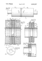
- FIG. 1 is a side view of a typical silencer having the vibration barrier mounted therein;
- FIG. 2 is a cross-sectional view taken at the line 2--2 of FIG. 1;
- FIG. 3 is a cross-sectional view similar to that of FIG. 2 but showing the barrier interposed in a pipeline;
- FIG. 4 is a plan view of a barrier plate
- FIG. 5 is a cross-sectional view of a barrier/connector of plastic material.
- FIG. 1 Illustrative embodiments and applications of the novel vibration barrier/structural connector are shown and described herein as used to vibrationally isolate one end of a silencer (FIGS. 1 and 2), interrupt the transmission of vibration in a pipeline or intake or outlet silencer nozzle (FIG. 3) and as employed to prevent the transmission of vibration between a nozzle and the shell of a plastic silencer structure (FIG. 5).
- the typical silencer illustrated in FIG. 1 has an inlet nozzle 1, an outlet nozzle 2 and a housing shell 3 which encloses the interior silencing structure including perforated tubes 4 and 5 and sound absorbing media 6. Washer-shaped headers 7 and 8 span the spaces between the perforated tubes and the shell, closing the media-filled chambers.
- the transmission of vibration from one end of the shell to the other is prevented, or at least substantially mitigated, by the interposition of the vibration barrier 9. If it is assumed that shell end portion 3a is driven in vibration by a vibrating inlet nozzle 1, or by the pulsations of a fluid stream conducted into the inlet end of the silencer through the inlet nozzle, the function of the vibration barrier 9 is to vibrationally isolate vibrating shell portion 3a so that shell end portion 3b is not subjected to vibration and outlet nozzle 2 will not drive the pipe or other structure with which it is connected in vibration.
- the vibration barrier 9 is composed of washer-shaped plates 10 and 11 which are substantially coextensive with header plates 7 and 8 and are spaced therefrom and from each other. Plates 10 and 11 are securely fastened at their outer peripheries 10a and 11a, respectively, with the outer peripheries of headers 7 and 8 by welding, as indicated. Plates 10 and 11 are not fastened together at their outer peripheries but are welded together at their inner peripheries 10b and 11b, as indicated. Bodies of vibration damping material, in the form of washers 12, 13 and 14, are sandwiched between the plates and between the plates and headers to occupy the spaces between these parts.
- silencer shell 3 is composed of steel
- headers 7 and 8 and plates 10 and 11 would also normally be fabricated from steel, giving them necessary structural strength.
- the vibration barrier-structural connector that emerges is a cantilever labyrinth which structurally connects the two portions of the silencer between which it is interposed.
- plate 10 which is firmly fastened at its outer periphery to header 7, serves as a cantilever to support plate 11 since it is securely fastened thereto at the inner peripheries of these plates.
- Plate 11 also serves as a cantilever to support header 8 to which it is securely fastened at the outer periphery of plate 11.
- the vibration barrier is shown as installed in a pipeline or in, for example, the inlet or outlet nozzle of a silencer.
- the outermost barrier plates 15 and 16 are welded at their inner peripheries to the end portions 17 and 18, respectively, of a pipe.
- the outer peripheries of plates 15 and 16 are securely fastened, as by welding, to the outer peripheries of spaced barrier plates 19 and 20 and the inner peripheries of plates 19 and 20 are fastened together as by welding.
- the cantilever labyrinth thus formed structurally supports the end portions of pipes 17 and 18. Washer-shaped bodies 21, 22 and 23 of vibration damping material are sandwiched between the four plates.
- FIG. 5 A vibration barrier/structural connector of plastic material is illustrated in FIG. 5.
- a first washer-shaped plate 24 is cemented upon the inner end of inlet nozzle 25.
- a second barrier plate 26 is securely fastened at its outer periphery to the outer periphery of plate 24 by means of a band 27 of plastic material.
- the inner peripheries of plate 26 and a third barrier plate 28 are fastened together by a plastic tubular section 29.
- the shell 30 of a silencer is cemented to the outer periphery of plate 28.
- washer-shaped bodies 31 and 32 of vibration damping material are sandwiched between the vibration barrier plates.
- This cantilever labyrinth structure with the vibration damping material embodied therein serves to prevent the transmission of vibration between inlet nozzle 25 and shell 30.
- the number of cantilever plates employed in the vibration barrier will depend upon the magnitude of the vibration problem. Since the vibratory motion is progressively damped from the input to the distal end of the barrier/connector, the effectiveness of the barrier increases with the number of plates.
- the barrier illustrated in FIG. 2 employs two cantilever plates, that of FIG. 3 incorporates four such plates, and the barrier structure of FIG. 5 employs three cantilever plates.
- the damping accomplished by interfacing plates 10 and 11 and vibration damping body 13 is augmented by the interaction of plates 10 and 11 and vibration damping bodies 12 and 14.
- the washer-shaped plates 10 and 11 and the washer-shaped vibration damping bodies 12, 13 and 14 are circular, they may, with equal effectiveness, be elliptical or otherwise shaped to conform to the shape of the silencer with which they are used.
- vibration barrier/structural connector of this invention exhibits satisfactory performance characteristics, being equal to or somewhat better than the vibration isolating connection structures shown in U.S. Pat. No. 3,894,610, they have a distinct advantage cost-wise. It is estimated that the cost of the barrier/connector of the present invention is approximately thirty percent less than that of the corresponding structure of the patent.
Landscapes
- Engineering & Computer Science (AREA)
- General Engineering & Computer Science (AREA)
- Mechanical Engineering (AREA)
- Exhaust Silencers (AREA)
- Pipe Accessories (AREA)
- Joints Allowing Movement (AREA)
Priority Applications (5)
| Application Number | Priority Date | Filing Date | Title |
|---|---|---|---|
| US05/654,119 US4045057A (en) | 1976-02-02 | 1976-02-02 | Vibration barrier/structural connector for conduits and the like |
| CA270,845A CA1045042A (en) | 1976-02-02 | 1977-02-01 | Vibration barrier/structural connector for conduits and the like |
| GB4238/77A GB1539629A (en) | 1976-02-02 | 1977-02-02 | Vibration damping connectors |
| FR7702934A FR2339804A1 (fr) | 1976-02-02 | 1977-02-02 | Raccord arretant les vibrations et destine notamment a des conduits |
| ES455573A ES455573A1 (es) | 1976-02-02 | 1977-02-02 | Conectador estructural y de barrera contra la vibracion paraconductos y similares. |
Applications Claiming Priority (1)
| Application Number | Priority Date | Filing Date | Title |
|---|---|---|---|
| US05/654,119 US4045057A (en) | 1976-02-02 | 1976-02-02 | Vibration barrier/structural connector for conduits and the like |
Publications (1)
| Publication Number | Publication Date |
|---|---|
| US4045057A true US4045057A (en) | 1977-08-30 |
Family
ID=24623498
Family Applications (1)
| Application Number | Title | Priority Date | Filing Date |
|---|---|---|---|
| US05/654,119 Expired - Lifetime US4045057A (en) | 1976-02-02 | 1976-02-02 | Vibration barrier/structural connector for conduits and the like |
Country Status (5)
| Country | Link |
|---|---|
| US (1) | US4045057A (OSRAM) |
| CA (1) | CA1045042A (OSRAM) |
| ES (1) | ES455573A1 (OSRAM) |
| FR (1) | FR2339804A1 (OSRAM) |
| GB (1) | GB1539629A (OSRAM) |
Cited By (12)
| Publication number | Priority date | Publication date | Assignee | Title |
|---|---|---|---|---|
| US4609214A (en) * | 1984-01-09 | 1986-09-02 | Compagnie Francaise Des Petroles | Thermally insulated fluid transport line |
| US5857712A (en) * | 1996-08-20 | 1999-01-12 | Sumitomo Rubber Industries, Ltd. | Cable damping device |
| US6543577B1 (en) * | 1997-11-21 | 2003-04-08 | Stephanus Ferreira | Silencer |
| US20050023076A1 (en) * | 2001-11-06 | 2005-02-03 | Huff Norman T. | Bumper/muffler assembly |
| US20050268500A1 (en) * | 2002-09-02 | 2005-12-08 | Kazuya Imamura | Vibration damping device and bucket for construction machine |
| US20070240934A1 (en) * | 2006-04-12 | 2007-10-18 | Van De Flier Peter | Long fiber thermoplastic composite muffler system |
| US20070240932A1 (en) * | 2006-04-12 | 2007-10-18 | Van De Flier Peter B | Long fiber thermoplastic composite muffler system with integrated reflective chamber |
| US20090078499A1 (en) * | 2007-09-26 | 2009-03-26 | Timothy Sikes | Muffler |
| US20090200795A1 (en) * | 2008-02-08 | 2009-08-13 | J. Eberspaecher Gmbh & Co. Kg | Component Connection |
| US20100307863A1 (en) * | 2007-12-14 | 2010-12-09 | Ocv Intellectual Capital, Llc | Composite muffler system thermosetable polymers |
| US20140284138A1 (en) * | 2013-03-21 | 2014-09-25 | Honda Motor Co., Ltd. | Engine muffler |
| US11719308B1 (en) * | 2020-12-05 | 2023-08-08 | Dongyuan Wang | Damping segmental ring structure for subway tunnels built in grim environments of deformable ground |
Citations (11)
| Publication number | Priority date | Publication date | Assignee | Title |
|---|---|---|---|---|
| US2126706A (en) * | 1935-12-23 | 1938-08-16 | Metalastik Ltd | Pipe connection |
| US2233804A (en) * | 1938-07-18 | 1941-03-04 | Maxim Silencer Co | Fluid silencer |
| GB722241A (en) * | 1952-11-07 | 1955-01-19 | English Electric Co Ltd | Improvements in and relating to expansion pieces for pipes |
| CH306733A (de) * | 1951-10-03 | 1955-04-30 | Parsons & Marine Eng Turbine | Biegsame Rohrverbindung. |
| US2920656A (en) * | 1956-10-19 | 1960-01-12 | Us Gasket Company | Reinforced bellows |
| US3061039A (en) * | 1957-11-14 | 1962-10-30 | Joseph J Mascuch | Fluid line sound-absorbing structures |
| US3190680A (en) * | 1960-06-06 | 1965-06-22 | Union Oil Co | Flexible coupling |
| US3232640A (en) * | 1960-09-14 | 1966-02-01 | Calumet & Hecla | Multi-wall flexible connector with interply pressurization |
| DE1650009A1 (de) * | 1967-07-06 | 1970-08-27 | Grohe Armaturen Friedrich | Geraeuschminderndes Anschlussstueck fuer Sanitaerarmaturen |
| US3606392A (en) * | 1969-04-14 | 1971-09-20 | Smith Ind International Inc | Vibration dampener |
| US3894610A (en) * | 1974-08-20 | 1975-07-15 | Burgess Ind | Gas stream silencer |
-
1976
- 1976-02-02 US US05/654,119 patent/US4045057A/en not_active Expired - Lifetime
-
1977
- 1977-02-01 CA CA270,845A patent/CA1045042A/en not_active Expired
- 1977-02-02 ES ES455573A patent/ES455573A1/es not_active Expired
- 1977-02-02 GB GB4238/77A patent/GB1539629A/en not_active Expired
- 1977-02-02 FR FR7702934A patent/FR2339804A1/fr active Granted
Patent Citations (11)
| Publication number | Priority date | Publication date | Assignee | Title |
|---|---|---|---|---|
| US2126706A (en) * | 1935-12-23 | 1938-08-16 | Metalastik Ltd | Pipe connection |
| US2233804A (en) * | 1938-07-18 | 1941-03-04 | Maxim Silencer Co | Fluid silencer |
| CH306733A (de) * | 1951-10-03 | 1955-04-30 | Parsons & Marine Eng Turbine | Biegsame Rohrverbindung. |
| GB722241A (en) * | 1952-11-07 | 1955-01-19 | English Electric Co Ltd | Improvements in and relating to expansion pieces for pipes |
| US2920656A (en) * | 1956-10-19 | 1960-01-12 | Us Gasket Company | Reinforced bellows |
| US3061039A (en) * | 1957-11-14 | 1962-10-30 | Joseph J Mascuch | Fluid line sound-absorbing structures |
| US3190680A (en) * | 1960-06-06 | 1965-06-22 | Union Oil Co | Flexible coupling |
| US3232640A (en) * | 1960-09-14 | 1966-02-01 | Calumet & Hecla | Multi-wall flexible connector with interply pressurization |
| DE1650009A1 (de) * | 1967-07-06 | 1970-08-27 | Grohe Armaturen Friedrich | Geraeuschminderndes Anschlussstueck fuer Sanitaerarmaturen |
| US3606392A (en) * | 1969-04-14 | 1971-09-20 | Smith Ind International Inc | Vibration dampener |
| US3894610A (en) * | 1974-08-20 | 1975-07-15 | Burgess Ind | Gas stream silencer |
Cited By (24)
| Publication number | Priority date | Publication date | Assignee | Title |
|---|---|---|---|---|
| US4609214A (en) * | 1984-01-09 | 1986-09-02 | Compagnie Francaise Des Petroles | Thermally insulated fluid transport line |
| US5857712A (en) * | 1996-08-20 | 1999-01-12 | Sumitomo Rubber Industries, Ltd. | Cable damping device |
| US6543577B1 (en) * | 1997-11-21 | 2003-04-08 | Stephanus Ferreira | Silencer |
| US20050023076A1 (en) * | 2001-11-06 | 2005-02-03 | Huff Norman T. | Bumper/muffler assembly |
| US7325652B2 (en) | 2001-11-06 | 2008-02-05 | Ocv Intellectual Capital, Llc | Bumper/muffler assembly |
| US7681689B2 (en) * | 2002-09-02 | 2010-03-23 | Komatsu Ltd. | Vibration damping device and bucket for construction machine |
| US20050268500A1 (en) * | 2002-09-02 | 2005-12-08 | Kazuya Imamura | Vibration damping device and bucket for construction machine |
| US8438759B2 (en) | 2002-09-02 | 2013-05-14 | Komatsu, Ltd. | Vibration damping device and bucket for construction machine |
| US20080222928A1 (en) * | 2002-09-02 | 2008-09-18 | Kazuya Imamura | Vibration damping device and bucket for construction machine |
| US20100218403A1 (en) * | 2002-09-02 | 2010-09-02 | Kazuya Imamura | Vibration damping device and bucket for construction machine |
| US7743881B2 (en) | 2002-09-02 | 2010-06-29 | Komatsu Ltd. | Vibration damping device and bucket for construction machine |
| EP1900913A1 (en) | 2003-12-31 | 2008-03-19 | Owens Corning | Muffler assembly |
| US20070240932A1 (en) * | 2006-04-12 | 2007-10-18 | Van De Flier Peter B | Long fiber thermoplastic composite muffler system with integrated reflective chamber |
| US7934580B2 (en) | 2006-04-12 | 2011-05-03 | Ocv Intellectual Capital, Llc | Long fiber thermoplastic composite muffler system |
| US7942237B2 (en) | 2006-04-12 | 2011-05-17 | Ocv Intellectual Capital, Llc | Long fiber thermoplastic composite muffler system with integrated reflective chamber |
| US20070240934A1 (en) * | 2006-04-12 | 2007-10-18 | Van De Flier Peter | Long fiber thermoplastic composite muffler system |
| US20090078499A1 (en) * | 2007-09-26 | 2009-03-26 | Timothy Sikes | Muffler |
| US7810609B2 (en) * | 2007-09-26 | 2010-10-12 | Chrysler Group Llc | Muffler |
| US20100307863A1 (en) * | 2007-12-14 | 2010-12-09 | Ocv Intellectual Capital, Llc | Composite muffler system thermosetable polymers |
| US20090200795A1 (en) * | 2008-02-08 | 2009-08-13 | J. Eberspaecher Gmbh & Co. Kg | Component Connection |
| US8678445B2 (en) * | 2008-02-08 | 2014-03-25 | J. Eberspaecher Gmbh & Co. Kg | Component connection |
| US20140284138A1 (en) * | 2013-03-21 | 2014-09-25 | Honda Motor Co., Ltd. | Engine muffler |
| US8950547B2 (en) * | 2013-03-21 | 2015-02-10 | Honda Motor Co., Ltd. | Engine muffler |
| US11719308B1 (en) * | 2020-12-05 | 2023-08-08 | Dongyuan Wang | Damping segmental ring structure for subway tunnels built in grim environments of deformable ground |
Also Published As
| Publication number | Publication date |
|---|---|
| GB1539629A (en) | 1979-01-31 |
| FR2339804A1 (fr) | 1977-08-26 |
| FR2339804B3 (OSRAM) | 1979-10-05 |
| ES455573A1 (es) | 1978-02-01 |
| CA1045042A (en) | 1978-12-26 |
Similar Documents
| Publication | Publication Date | Title |
|---|---|---|
| US4045057A (en) | Vibration barrier/structural connector for conduits and the like | |
| US2233804A (en) | Fluid silencer | |
| US5506376A (en) | Apparatus for absorbing vibrations in an exhaust system of a vehicle | |
| US3420553A (en) | Apparatus for absorbing sound and vibration in a piping system | |
| US4880078A (en) | Exhaust muffler | |
| US6155378A (en) | Method and apparatus for noise suppression in a fluid line | |
| US5482330A (en) | Apparatus for the flexible connection of pipes in exhaust lines of motor vehicles | |
| KR20010020350A (ko) | 가압유체 전달 시스템용 에너지 감쇠장치 및 에너지 감쇠방법 | |
| CN108561669B (zh) | 弹性背腔式管路减振消声装置 | |
| US3038553A (en) | Flexible fluid coupling and sound attenuating assemblies | |
| JP2000227024A (ja) | 自動車エキゾ―ストパイプ用パイプエレメント | |
| JPH10331630A (ja) | 排気マニホルド取り付け装置およびそれを製造する方法 | |
| JP2683162B2 (ja) | 遠心圧縮機用消音装置及びその組込方法 | |
| US3132717A (en) | Acoustically absorbent conduit | |
| JP5484488B2 (ja) | ターボ機械又はピストン機械用のマフラ | |
| JP6660267B2 (ja) | セラミックフィルタの保護装着用部材 | |
| US3524476A (en) | Pipe wall shear damping treatment | |
| US3669471A (en) | Flexible connecting device | |
| US2766840A (en) | Vibration absorber | |
| JPH0432208B2 (OSRAM) | ||
| US2516949A (en) | Muffler with inner sound-absorbing tube | |
| JPH08303679A (ja) | 配管制振継手 | |
| JPH08285170A (ja) | 防振管継手 | |
| CN114810885A (zh) | 振动抑制条带以及消音器 | |
| JPS5822679B2 (ja) | 管路の防振装置 |
Legal Events
| Date | Code | Title | Description |
|---|---|---|---|
| AS | Assignment |
Owner name: NITRAM-TEXAS, INC., S-3865 TAYLOR ROAD, ORCHARD PA Free format text: ASSIGNMENT OF ASSIGNORS INTEREST.;ASSIGNOR:BURGESS INDUSTRIES INCORPORATED;REEL/FRAME:004279/0966 Effective date: 19840614 |
|
| AS | Assignment |
Owner name: BURGESS-MANNING, INC. Free format text: CHANGE OF NAME;ASSIGNOR:NITRAM-TEXAS, INC.;REEL/FRAME:004307/0001 Effective date: 19840618 |