US4044912A - Lined container for storing and transporting thick viscous substances such as grease having anti-clogging liner support - Google Patents
Lined container for storing and transporting thick viscous substances such as grease having anti-clogging liner support Download PDFInfo
- Publication number
- US4044912A US4044912A US05/693,101 US69310176A US4044912A US 4044912 A US4044912 A US 4044912A US 69310176 A US69310176 A US 69310176A US 4044912 A US4044912 A US 4044912A
- Authority
- US
- United States
- Prior art keywords
- bag
- spacer assembly
- frame members
- secured
- hub member
- Prior art date
- Legal status (The legal status is an assumption and is not a legal conclusion. Google has not performed a legal analysis and makes no representation as to the accuracy of the status listed.)
- Expired - Lifetime
Links
Images
Classifications
-
- B—PERFORMING OPERATIONS; TRANSPORTING
- B65—CONVEYING; PACKING; STORING; HANDLING THIN OR FILAMENTARY MATERIAL
- B65D—CONTAINERS FOR STORAGE OR TRANSPORT OF ARTICLES OR MATERIALS, e.g. BAGS, BARRELS, BOTTLES, BOXES, CANS, CARTONS, CRATES, DRUMS, JARS, TANKS, HOPPERS, FORWARDING CONTAINERS; ACCESSORIES, CLOSURES, OR FITTINGS THEREFOR; PACKAGING ELEMENTS; PACKAGES
- B65D25/00—Details of other kinds or types of rigid or semi-rigid containers
- B65D25/14—Linings or internal coatings
- B65D25/18—Linings or internal coatings spaced appreciably from container wall
-
- B—PERFORMING OPERATIONS; TRANSPORTING
- B65—CONVEYING; PACKING; STORING; HANDLING THIN OR FILAMENTARY MATERIAL
- B65D—CONTAINERS FOR STORAGE OR TRANSPORT OF ARTICLES OR MATERIALS, e.g. BAGS, BARRELS, BOTTLES, BOXES, CANS, CARTONS, CRATES, DRUMS, JARS, TANKS, HOPPERS, FORWARDING CONTAINERS; ACCESSORIES, CLOSURES, OR FITTINGS THEREFOR; PACKAGING ELEMENTS; PACKAGES
- B65D88/00—Large containers
- B65D88/54—Large containers characterised by means facilitating filling or emptying
- B65D88/58—Large containers characterised by means facilitating filling or emptying by displacement of walls
- B65D88/60—Large containers characterised by means facilitating filling or emptying by displacement of walls of internal walls
- B65D88/62—Large containers characterised by means facilitating filling or emptying by displacement of walls of internal walls the walls being deformable
Definitions
- This invention relates generally to material handling apparatus and more specifically to a tank for storing and transporting thick viscous substances such as grease.
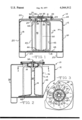
- FIG. 2 is a sectional view like FIG. 1 of the container of this invention showing the bag in collapsed position;
- FIG. 3 is a top view of the container taken substantially at the line 3--3 of FIG. 2.
- the container of this invention shown generally at 10 in FIG. 1, consists of a rectangular tank 12, a collapsible bag 14 and a spacer assembly 16.
- the rectangular tank 12 has a bottom wall 18, side wall 20 and a top wall 22 provided with a filling and discharge opening 24 about which an upright flange 28 is integrally formed with the top wall 22.
- Container legs 25 are provided to aid in storing and transporting the tank 10.
- the spacer assembly 16 is positioned inside the bag 14 to surround the pipe 34 and consists of a plurality of C-shaped frame members 42, each having a main portion 43 and laterally extending ends 44.
- the frame members 42 radiate outwardly from the hub 38 and from the pipe 34 an equal distance as shown in FIG. 3 so that they form a vane-like arrangement.
- the frame members 42 are spaced apart a distance sufficient to form a passageway 50 (FIG. 2) when the bag 14 is completely collapsed about the assembly 16.
- the circumferential distance of the expanded bag 14 approximates the perimetrical distance about the spacer assembly 16 so that the bag 14 remains relatively unstretched and does not fold over itself when collapsed about the spacer assembly 16.
- the container 10 is filled with grease so that the bag 14 expands to the position shown in FIG. 1.
- a vacuum pump, or other similar device connected to the pipe 34 is to be used.
- the bag 14 collapses about the spacer assembly 16.
- the spacer assembly 16 prevents it from obstructing the pipe 34.
- FIGS. 2 and 3 show the bag 14 completely collapsed about the spacer assembly 16 and, as can be seen, the passageway 50 is formed between the pipe 34 and the retainer plate 48.
Landscapes
- Engineering & Computer Science (AREA)
- Mechanical Engineering (AREA)
- Packages (AREA)
Abstract
Description
Claims (5)
Priority Applications (1)
| Application Number | Priority Date | Filing Date | Title |
|---|---|---|---|
| US05/693,101 US4044912A (en) | 1976-06-04 | 1976-06-04 | Lined container for storing and transporting thick viscous substances such as grease having anti-clogging liner support |
Applications Claiming Priority (1)
| Application Number | Priority Date | Filing Date | Title |
|---|---|---|---|
| US05/693,101 US4044912A (en) | 1976-06-04 | 1976-06-04 | Lined container for storing and transporting thick viscous substances such as grease having anti-clogging liner support |
Publications (1)
| Publication Number | Publication Date |
|---|---|
| US4044912A true US4044912A (en) | 1977-08-30 |
Family
ID=24783309
Family Applications (1)
| Application Number | Title | Priority Date | Filing Date |
|---|---|---|---|
| US05/693,101 Expired - Lifetime US4044912A (en) | 1976-06-04 | 1976-06-04 | Lined container for storing and transporting thick viscous substances such as grease having anti-clogging liner support |
Country Status (1)
| Country | Link |
|---|---|
| US (1) | US4044912A (en) |
Cited By (6)
| Publication number | Priority date | Publication date | Assignee | Title |
|---|---|---|---|---|
| DE2900998A1 (en) * | 1979-01-12 | 1980-07-17 | Nittel Josef Kg | Sheath around collapsed flexible lining for rigid container - locates and gradually releases lining during filling with liquid from below to smooth out creases |
| US5139168A (en) * | 1990-02-28 | 1992-08-18 | L'oreal | Assembly for dispensing a product in which the product to be dispensed is contained in a flexible pouch |
| US6068152A (en) * | 1997-12-01 | 2000-05-30 | Wacker-Chemie Gmbh | Shipping container for highly viscous fluids and/or pastes |
| US6168051B1 (en) | 2000-02-24 | 2001-01-02 | Timothy L. Poppell | Hot fluid transfer mechanism |
| USD667699S1 (en) | 2011-10-03 | 2012-09-25 | Camco Manufacturing, Inc. | Grease storage container |
| US9016508B1 (en) | 2012-11-05 | 2015-04-28 | Joseph Paul Leighton | Container with movable bottom plate |
Citations (8)
| Publication number | Priority date | Publication date | Assignee | Title |
|---|---|---|---|---|
| US2954892A (en) * | 1958-07-09 | 1960-10-04 | Conch Int Methane Ltd | Vessel for storing cold liquids |
| US3122000A (en) * | 1962-03-30 | 1964-02-25 | Paul J Sirocky | Apparatus for transferring cryogenic liquids |
| US3383875A (en) * | 1966-08-17 | 1968-05-21 | Andrew Corp | Conduit for cryogenic fluids |
| US3388832A (en) * | 1965-10-22 | 1968-06-18 | African Explosives & Chem | Method of and apparatus for dispensing fluent materials |
| US3389833A (en) * | 1965-10-30 | 1968-06-25 | Idees | Dispensing container |
| US3420413A (en) * | 1967-08-14 | 1969-01-07 | Diamond Int Corp | Liquid and paste dispenser |
| US3590888A (en) * | 1966-12-05 | 1971-07-06 | Clarence B Coleman | Composite container and method of handling fluent materials |
| US3747800A (en) * | 1971-02-16 | 1973-07-24 | C Viland | Preventing air pollution and improving safety of automobile and similar tanks |
-
1976
- 1976-06-04 US US05/693,101 patent/US4044912A/en not_active Expired - Lifetime
Patent Citations (8)
| Publication number | Priority date | Publication date | Assignee | Title |
|---|---|---|---|---|
| US2954892A (en) * | 1958-07-09 | 1960-10-04 | Conch Int Methane Ltd | Vessel for storing cold liquids |
| US3122000A (en) * | 1962-03-30 | 1964-02-25 | Paul J Sirocky | Apparatus for transferring cryogenic liquids |
| US3388832A (en) * | 1965-10-22 | 1968-06-18 | African Explosives & Chem | Method of and apparatus for dispensing fluent materials |
| US3389833A (en) * | 1965-10-30 | 1968-06-25 | Idees | Dispensing container |
| US3383875A (en) * | 1966-08-17 | 1968-05-21 | Andrew Corp | Conduit for cryogenic fluids |
| US3590888A (en) * | 1966-12-05 | 1971-07-06 | Clarence B Coleman | Composite container and method of handling fluent materials |
| US3420413A (en) * | 1967-08-14 | 1969-01-07 | Diamond Int Corp | Liquid and paste dispenser |
| US3747800A (en) * | 1971-02-16 | 1973-07-24 | C Viland | Preventing air pollution and improving safety of automobile and similar tanks |
Cited By (6)
| Publication number | Priority date | Publication date | Assignee | Title |
|---|---|---|---|---|
| DE2900998A1 (en) * | 1979-01-12 | 1980-07-17 | Nittel Josef Kg | Sheath around collapsed flexible lining for rigid container - locates and gradually releases lining during filling with liquid from below to smooth out creases |
| US5139168A (en) * | 1990-02-28 | 1992-08-18 | L'oreal | Assembly for dispensing a product in which the product to be dispensed is contained in a flexible pouch |
| US6068152A (en) * | 1997-12-01 | 2000-05-30 | Wacker-Chemie Gmbh | Shipping container for highly viscous fluids and/or pastes |
| US6168051B1 (en) | 2000-02-24 | 2001-01-02 | Timothy L. Poppell | Hot fluid transfer mechanism |
| USD667699S1 (en) | 2011-10-03 | 2012-09-25 | Camco Manufacturing, Inc. | Grease storage container |
| US9016508B1 (en) | 2012-11-05 | 2015-04-28 | Joseph Paul Leighton | Container with movable bottom plate |
Similar Documents
| Publication | Publication Date | Title |
|---|---|---|
| US4793519A (en) | Composite shipping container | |
| US4418835A (en) | Trash container apparatus | |
| US5217138A (en) | Liquid transport drum with removable liner | |
| US5143242A (en) | Paint bucket with disposable liner | |
| US5335821A (en) | Liquid chemical container and dispensing system | |
| US3918605A (en) | Combination container with disposable closure and linear assembly | |
| EP0034025B1 (en) | Emptiable container for bulk material and having a follower for the material | |
| US2905560A (en) | Methods and means for handling milk | |
| US5156268A (en) | Composite shipping container for combustible liquids | |
| CA2208808C (en) | Tank liner | |
| US4044912A (en) | Lined container for storing and transporting thick viscous substances such as grease having anti-clogging liner support | |
| US6047846A (en) | Plastic drum with drain sump | |
| US3162331A (en) | Transportable container | |
| US5005726A (en) | Composite container assemblies | |
| US2861714A (en) | Shipping unit | |
| AU640045B2 (en) | Liquid transport drum with removable liner | |
| US2764545A (en) | Sectional septic tank | |
| US5692631A (en) | Container for transporting, storing and dispensing chemical products | |
| US1913652A (en) | Container top | |
| KR102431254B1 (en) | plastic liner with inner lining | |
| GB1214017A (en) | Improvements relating to containers with controlled discharge | |
| US3186607A (en) | Container | |
| WO1988008401A1 (en) | Drum liner | |
| US3162330A (en) | Transportable container | |
| US2258285A (en) | Nesting shipping drum with hoops therefor |
Legal Events
| Date | Code | Title | Description |
|---|---|---|---|
| AS | Assignment |
Owner name: HOOVER GROUP, INC., A CORP. OF DE. Free format text: ASSIGNMENT OF ASSIGNORS INTEREST.;ASSIGNOR:HOOVER UNIVERSAL, INC.;REEL/FRAME:004502/0191 Effective date: 19851031 Owner name: FIRST NATIONAL BANK OF BOSTON, THE Free format text: SECURITY INTEREST;ASSIGNOR:HOOVER GROUP, INC., A CORP. OF DE.;REEL/FRAME:004492/0790 Effective date: 19851107 |
|
| STCF | Information on status: patent grant |
Free format text: PATENTED FILE - (OLD CASE ADDED FOR FILE TRACKING PURPOSES) |
|
| AS | Assignment |
Owner name: HOOVER GROUP, INC. Free format text: RELEASED BY SECURED PARTY;ASSIGNOR:FIRST NATIONAL BANK OF BOSTON, THE;REEL/FRAME:005580/0097 Effective date: 19900531 |
|
| AS | Assignment |
Owner name: NATIONSBANK OF GEORGIA, N.A., AS AGENT, GEORGIA Free format text: CONDITIONAL ASSIGNMENT;ASSIGNOR:HOOVER GROUP, INC.;REEL/FRAME:007046/0409 Effective date: 19940607 |