US4044602A - Consistometer with internal calibration means - Google Patents
Consistometer with internal calibration means Download PDFInfo
- Publication number
- US4044602A US4044602A US05/719,626 US71962676A US4044602A US 4044602 A US4044602 A US 4044602A US 71962676 A US71962676 A US 71962676A US 4044602 A US4044602 A US 4044602A
- Authority
- US
- United States
- Prior art keywords
- signal
- pulse
- pulses
- flop
- flip
- Prior art date
- Legal status (The legal status is an assumption and is not a legal conclusion. Google has not performed a legal analysis and makes no representation as to the accuracy of the status listed.)
- Expired - Lifetime
Links
Images
Classifications
-
- G—PHYSICS
- G01—MEASURING; TESTING
- G01N—INVESTIGATING OR ANALYSING MATERIALS BY DETERMINING THEIR CHEMICAL OR PHYSICAL PROPERTIES
- G01N11/00—Investigating flow properties of materials, e.g. viscosity, plasticity; Analysing materials by determining flow properties
- G01N11/10—Investigating flow properties of materials, e.g. viscosity, plasticity; Analysing materials by determining flow properties by moving a body within the material
- G01N11/14—Investigating flow properties of materials, e.g. viscosity, plasticity; Analysing materials by determining flow properties by moving a body within the material by using rotary bodies, e.g. vane
Definitions
- the present invention relates to measuring apparatus in general and, more particularly, to consistometers.
- a consistometer which continuously measures the consistency of a stream of material provided by apparatus manufacturing the material includes a rotatable resilient member located in the stream and a reference member located outside of the stream. The two members are rotated synchronously.
- the consistometer also includes two sensors, each sensor sensing the passage of a corresponding member and provides the signal in accordance with the passage of the member.
- a circuit connected to the sensors provides an enabling pulse in accordance with the signals from the sensors.
- a comparator connected to the sensor sensing the passage of the reference member compares the signal from that sensor with a predetermined voltage corresponding to an acceptable signal level when enabled by the enabling pulse from the circuit and provides a comparison signal of one level when the reference member signal is an acceptable signal and of another level when the reference member signal is not an acceptable signal or when the comparator has not been enabled by an enabling pulse.
- Pulse circuits connected to the comparator and to the resilient member sensor provide a reference member pulse and a resilient member pulse in accordance with the comparison signal and the resilient member signal, respectively.
- a flip-flop receiving the reference member pulses and the resilient member pulses provides a signal corresponding to the consistency of the material in accordance with the pulses.
- the consistometer also has a calibration circuit.
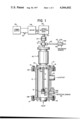
- FIG. 1 is a combined simplified block diagram and a mechanical view of a portion of a consistometer constructed in accordance with the present invention.
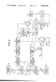
- FIG. 2 is a simplified block diagram of the remaining portion of the consistometer constructed in accordance with the present invention.
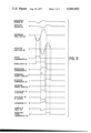
- FIGS. 3A through 3O are graphical representations of signals occurring within the consistometer during operation thereof.
- a consistometer apparatus embodying features of the present invention, wherein a chamber 11 is defined by tubular side walls 12 of appropriate steel or other material suitable to maintain the grease or other material whose consistency is to be measured and having upper and lower end plates, 13, 14 bolted to respective upper and lower flanges 12A, 12B on chamber member 12 by means of bolts 15, 16, 17, 18.
- a inlet conduit 19 At the lower end of chamber 11, in lower end plate 14, there is provided an opening for receiving an inlet conduit 19 through which material, such as grease, the consistency of which is to be measured, may be introduced under appropriate pressure in a continuous stream.
- An outlet conduit 20 is provided at an upper portion of sidewall 12 of chamber 11 for outputting a stream of the material passing through chamber 11 for consistency measurement.
- a shaft 21 extending into chamber 11 through an opening 22 in upper plate 13 from a stuffing box arrangement 23 containing appropriate means for sealing fluid within the chamber under appropriate pressure from bearings (not shown) in a bearing assembly 24 through which shaft 21 extends upwardly to a mechanical coupling 25 from whence it is driven by means of a speed reduction gear 26 which, in turn, is coupled by means of a drive shaft 27 to an electric motor 28.
- Electric motor 28 provides means for driving shaft 21 at a constant speed and is, in turn, electrically coupled to a suitable power supply 29 through appropriate conductors including a switch 30.
- shaft 21 within chamber 11 has affixed thereto a mounting assembly 31, shown threaded to the lower end of shaft 21, for attaching a resilient reference blade member 32 to shaft 21.
- Blade 32 is mounted to shaft 21 so that the two surfaces about which it is flexible are parallel to the direction of the flow of the material in the stream passing upwardly from inlet 19 through chamber 11 and thence out through outlet 20.
- Shaft 21 including assembly 31 and resilient member 32 mounted thereon are rotated at a constant rate as the material being measured is passed through chamber 11 in the direction of the arrow shown below inlet 19 in the drawing.
- Blade 32 may be formed of steel capable of deflection in the material being measured, such as grease, and the end of the blade will be deflected as it rotates in the material by an amount dependent upon the reaction forces exerted thereon by the material as an indication of the consistency of such material.
- Means are provided for substantially continuously measuring the amount of flexure of resilient member 32 as a measure of the consistency of the material passing through chamber 11.
- a reference member 40 is mounted on shaft 21 by means of a mounting assembly 41 which may be in the form of a collar having an appropriate set screw therein for facilitating adjustment of the position of member 40 on shaft 21 relative to the position of resilient member 32 on shaft 21, as will be discussed in further detail hereinafter. It will be seen from the above that resilient member 32 and relatively rigid member 40, both being mounted to shaft 21, will rotate in synchronism as the shaft is rotated by motor 28.
- resilient member 32 and relatively rigid reference member 40 are mounted to shaft 21 so that they lie in substantially the same plane as the central axis of shaft 21 when resilient member 32 is in its normal position, i.e., not subjected to forces tending to deflect same.
- the reference and the resilient members may also lie in a different plane, but such is not necessary.
- Means for measuring this deflection of member 32 comprising a first detector or sensor, referred to as detector sensor 42, opposite the resilient member 32, and a second detector or sensor, referred to as reference sensor 43, opposite rigid member 40.
- Sensors 42, 43 preferably comprise magnetic sensors responsive to the passage of respective blades 32 and 40.
- sensors 42, 43 advantageously comprise respective magnetic sensors mounted within relatively rugged shells or housings formed of stainless steel or the like to withstand the conditions and materials encountered within chamber 11 as the stream of material being measured passes through.
- Sensor 42 is shown mounted within an opening 42A in wall 12 of chamber 11, whereby the magnetic sensor is able to detect flexible detector blade 32 magnetically, without itself being placed within the material passing through chamber 11.
- Reference sensor 43 is mounted through the use of appropriate means (not shown) for maintaining it opposite rigid reference blade member 40 so that the reference sensor 43 may sense or detect reference member 40 magnetically as it moves past same.
- the magnetic sensor of sensor 43 may also be mounted within a casing of stainless steel or the like similar to that employed for enclosing sensor 42.
- rigid reference member 40 is shown mounted to shaft 21 at a location outside of chamber 11. This is the preferred embodiment, since it permits adjustment of the reference blade. However, it is possible to construct apparatus of the type herein disclosed wherein rigid reference member 40 is mounted to a portion of shaft 21 within chamber 11. In such event, rigid member 40 should be affixed to the shaft at a position downstream from the flexible blade (above flexible blade 32, as shown in FIG. 1) a sufficient distance to avoid producing any adverse effect on the consistency of the material flowing through chamber 11 prior to its passing flexible member 32.
- the reference member may comprise a nonmagnetic disc with a magnetic inset, in which event the likelihood of turbulence within chamber 11 is substantially eliminated.
- reference member 40 should be positioned within chamber 11, it may be desirable to provide a longer chamber 11 than otherwise so that reference member 40 can be spaced beyond the position where it might otherwise influence the consistency of the material whose consistency is being measured by flexible member 32.
- reference sensor 43 should be positioned within an opening in side wall 12 of chamber 11 in a manner similar to the positioning of sensor 42 and may advantageously be positioned between the location of outlet 20 and the upper end of chamber 11 as shown in FIG. 1.
- member 32 is here described as flexible in comparison to rigid reference member 40. It is to be understood that the rigidity of member 40 is a relative term, depending upon its environment. Accordingly, when mounted outside of chamber 11 so that member 40 is in the surrounding air, it will not need to be so rigid or still as when positioned within chamber 11 for rotation in the material being measured as discussed above.
- flexible member 32 and reference member 40 are shown positioned in the same plane, it is possible to position the two members in different planes displaced around the axis of shaft 21 or otherwise mount same for rotation in synchronism, so long as the two sensors are positioned opposite the respective members such that when there is no material in chamber 11 or when the resilient member 32 is stationary in the material in chamber 11, the two members are in phase at their zero points, namely, flexible member 32 and rigid member 40 are both opposite the center of respective sensors 42, 43 at the same time such that when rotated in flowing material under operating conditions flexible member 32 will be deflected from the corresponding rotational point of reference member 40 by an amount that is measurable by means of the respective detectors 42, 43 for determination of the amount of flexure of blade 32 due to the consistency of the material passing through chamber 11.
- Reference sensor 43 provides a signal A, as shown in FIG. 3A, to a reference amplifier 46 which provides an output C shown in FIG. 3C to a noise comparator 50 and to a reference comparator 51.
- the output C of amplifier 46 is similar to a one cycle sine wave for each passage of member 40 past reference sensor 43, going from a zero reference to a negative peak swinging back to a positive peak and then to zero.
- Noise comparator 50 is a conventional type comparator receiving a negative signal (not shown) of a predetermined value corresponding to a noise level.
- An output E provided by noise comparator 50 shown in FIG.
- Noise comparator 50 provides signal E as a pulse having a duration corresponding to the length of time that the negative peak of signal C exceeds the noise level.
- Signal E is applied to a noise latch 55.
- detector sensor 42 shown in FIG. 3B
- the output of detector sensor 42 is amplified by an amplifier 56 to provide a signal D, shown in FIG. 3D, corresponding to the passage of member 32 past detector sensor 42.
- Detector comparator 59 also receives a positive signal (not shown) corresponding to a predetermined acceptable signal from detector amplifier 56 and provides a signal I, shown in FIG. 3I, to noise latch 55.
- the amplitude of the positive signal is close to zero, so as the signal D goes from a negative to positive signal I from comparator 59 goes to a high level.
- noise latch 55 is such that when noise comparator 50 determines that signal C is not noise, signal E causes noise latch 55 to provide a signal F, shown in FIG. 3F, at a high logic level which is applied to reference comparator 51 enabling comparator 51 to make a comparison of signal C.
- signal A is noise
- signal C causes comparator 50 to provide signal E at a low level and therefore noise latch 55 is not able to provide signal F at a high level so that comparator 51 cannot compare the noise being provided by amplifier 46.
- signal F initially goes to a high level in response to an output from comparator 50.
- Detector comparator 59 detecting that there is a signal D provides signal I at a high level to noise latch 55 to reset it causing signal F to go to a low level and thus prevent the comparison of any noise coming out of amplifier 46.
- Reference comparator 51 provides signal G at a high level in response to the reference signal C crossing the zero reference line going from a negative peak to a positive peak where it remains until signal C returns to its zero level causing signal G to go to a low level thereby forming a pulse. Duration of that pulse has no significant meaning. However, the leading edge of the G pulse is conditioned by reference signal conditioner 64 to provide a pulse H, shown in FIG. 3H, to a reference signal gate 65, which provides pulse H to a flip-flop 70, except as hereinafter explained. Flip-flop 70 provides its Q and Q outputs as signals K and L, respectively, shown in FIGS.
- Signals K, L are at high and low levels, respectively, when flip-flop 70 is in a set state, and are at reversed levels when flip-flop 70 is in a clear state.
- Flip-flop 70 is triggered by pulse H to a set state.
- detector signal conditioner 60 In response to signal I going to a high level, detector signal conditioner 60 provides a pulse J, shown in FIG. 3J, to a detector signal gate 129, which provides pulse J to flip-flop 70 except as hereinafter explained. Flip-flop 70 is reset to a clear state by a pulse from gate 129.
- An integrator 73 integrates signal L to provide an output M, shown in FIG. 3M, to a sample and hold circuit 75 which is controlled by signal L. Sample and hold circuit 75 provides a signal N, corresponding to the grease's consistency, in accordance with signal M to an amplifier 80. Amplifier 80 amplifies signal N and provides it to a recorder 81. Recorder 81 provides a signal Q to a grease unit 85 for controlling the grease unit.
- the operation of the consistometer as hereinbefore described is similar to that of consistometers disclosed and described in the aforementioned U.S. Pat. Nos. 3,812,706 and 3,668,677.
- the present embodiment calls for a consistometer with internal calibration means.
- An enabling voltage V is applied to a manually operative switch 130.
- switch 130 passes voltage V to an inverter 131 which inverts voltage V to provide a disabling signal to reference signal gate 65 and to detector signal gate 129 to block the H and J pulses from reference signal conditioner 64 and detector signal conditioner 60, respectively.
- the passed voltage V is applied to a calibration gate 136 causing gate 136 to pass a pulse signal provided by calibration multivibrator 140.
- the pulses from calibration gate 136 are applied to a calibration latch 142 so that the first pulse sets calibration latch 142 causing its output to go to a high level.
- the output from latch 142 is applied to a calibration signal gate 147.
- the first pulse in the pulse signal from calibration signal conditioner 150 passes through calibration signal gate 147 and triggers flip-flop 70 to a set condition causing signal L to go to a low level.
- Signal L is also applied to a reset input of calibration latch 142; however, it does not reset latch 142 at this time.
- a second calibration pulse in the pulse signal from calibration signal conditioner 150 passes through calibration signal gate 147 and triggers flip-flop 70 to a clear state causing signal L to go to a high level.
- calibration latch 142 is reset so that no further pulses in the calibration pulse signal can pass through calibration signal gate 147 until another pulse in the pulse signal being provided by the calibration gate 136 triggers calibration latch 142.
- the frequency of the pulses in the pulse signal from calibration signal conditioner 150 is predetermined and known, therefore the duration of signal L being at a high level is predetermined and known, so that signal is suitable for use to calibrate the unit.
- the frequency of the pulse signal from multivibrator 140 controls the repetition of the calibration.
- the present invention as hereinbefore described is a consistometer having internal calibration. Periodically two pulses having a known time relationship to each other are provided to a flip-flop. The output of the flip-flop is a pulse having a known time duration. The flip-flop's pulse is used to calibrate an integrator.
Priority Applications (7)
| Application Number | Priority Date | Filing Date | Title |
|---|---|---|---|
| US05/719,626 US4044602A (en) | 1976-09-01 | 1976-09-01 | Consistometer with internal calibration means |
| BR7703687A BR7703687A (pt) | 1976-09-01 | 1977-06-07 | Consistometro para medicao continua da consistencia de um fluxo de material |
| GB31892/77A GB1552722A (en) | 1976-09-01 | 1977-07-29 | Consistometer with internal calibration means |
| ZA00774646A ZA774646B (en) | 1976-09-01 | 1977-08-01 | Consistometer with internal calibration means |
| AU27744/77A AU500828B1 (en) | 1976-09-01 | 1977-08-09 | Consistometer with internal calibration means |
| ES461841A ES461841A1 (es) | 1976-09-01 | 1977-08-23 | Un consistometro para medir continuamente la consistencia deuna corriente de material. |
| MX776054U MX4467E (es) | 1976-09-01 | 1977-08-30 | Mejoras a consistometros |
Applications Claiming Priority (1)
| Application Number | Priority Date | Filing Date | Title |
|---|---|---|---|
| US05/719,626 US4044602A (en) | 1976-09-01 | 1976-09-01 | Consistometer with internal calibration means |
Publications (1)
| Publication Number | Publication Date |
|---|---|
| US4044602A true US4044602A (en) | 1977-08-30 |
Family
ID=24890744
Family Applications (1)
| Application Number | Title | Priority Date | Filing Date |
|---|---|---|---|
| US05/719,626 Expired - Lifetime US4044602A (en) | 1976-09-01 | 1976-09-01 | Consistometer with internal calibration means |
Country Status (7)
| Country | Link |
|---|---|
| US (1) | US4044602A (es) |
| AU (1) | AU500828B1 (es) |
| BR (1) | BR7703687A (es) |
| ES (1) | ES461841A1 (es) |
| GB (1) | GB1552722A (es) |
| MX (1) | MX4467E (es) |
| ZA (1) | ZA774646B (es) |
Cited By (10)
| Publication number | Priority date | Publication date | Assignee | Title |
|---|---|---|---|---|
| US4250555A (en) * | 1979-01-22 | 1981-02-10 | Nortron Corporation | Self-calibrating data collection system for dynamic wheel balancing machine |
| US4253156A (en) * | 1979-06-22 | 1981-02-24 | The United States Of America As Represented By The Administrator Of The National Aeronautics And Space Administration | Automatic flowmeter calibration system |
| US4559811A (en) * | 1984-05-21 | 1985-12-24 | Texaco Inc. | Consistometer |
| US4622846A (en) * | 1985-11-05 | 1986-11-18 | Halliburton Company | Consistency and static gel strength measuring device and method |
| US4653313A (en) * | 1985-10-18 | 1987-03-31 | Halliburton Company | Positive stirring consistometer cup and method of using the same |
| US4668911A (en) * | 1985-11-26 | 1987-05-26 | Halliburton Company | Apparatus for making non-contact angular deflection measurements |
| US5003502A (en) * | 1988-10-25 | 1991-03-26 | Halliburton Company | Digital filter for random variable |
| US20040149019A1 (en) * | 2003-01-30 | 2004-08-05 | Johnson Johnny W. | Yield point adaptation for rotating viscometers |
| US6782735B2 (en) | 2000-02-08 | 2004-08-31 | Halliburton Energy Services, Inc. | Testing device and method for viscosified fluid containing particulate material |
| CN109085093A (zh) * | 2018-06-19 | 2018-12-25 | 于振海 | 一种混凝土维勃稠度仪 |
Citations (2)
| Publication number | Priority date | Publication date | Assignee | Title |
|---|---|---|---|---|
| US3668677A (en) * | 1970-12-30 | 1972-06-06 | Texaco Inc | Alarm system for consistometer |
| US3812706A (en) * | 1971-12-10 | 1974-05-28 | Texaco Inc | Consistometer |
-
1976
- 1976-09-01 US US05/719,626 patent/US4044602A/en not_active Expired - Lifetime
-
1977
- 1977-06-07 BR BR7703687A patent/BR7703687A/pt unknown
- 1977-07-29 GB GB31892/77A patent/GB1552722A/en not_active Expired
- 1977-08-01 ZA ZA00774646A patent/ZA774646B/xx unknown
- 1977-08-09 AU AU27744/77A patent/AU500828B1/en not_active Expired
- 1977-08-23 ES ES461841A patent/ES461841A1/es not_active Expired
- 1977-08-30 MX MX776054U patent/MX4467E/es unknown
Patent Citations (2)
| Publication number | Priority date | Publication date | Assignee | Title |
|---|---|---|---|---|
| US3668677A (en) * | 1970-12-30 | 1972-06-06 | Texaco Inc | Alarm system for consistometer |
| US3812706A (en) * | 1971-12-10 | 1974-05-28 | Texaco Inc | Consistometer |
Cited By (12)
| Publication number | Priority date | Publication date | Assignee | Title |
|---|---|---|---|---|
| US4250555A (en) * | 1979-01-22 | 1981-02-10 | Nortron Corporation | Self-calibrating data collection system for dynamic wheel balancing machine |
| US4253156A (en) * | 1979-06-22 | 1981-02-24 | The United States Of America As Represented By The Administrator Of The National Aeronautics And Space Administration | Automatic flowmeter calibration system |
| US4559811A (en) * | 1984-05-21 | 1985-12-24 | Texaco Inc. | Consistometer |
| US4653313A (en) * | 1985-10-18 | 1987-03-31 | Halliburton Company | Positive stirring consistometer cup and method of using the same |
| US4622846A (en) * | 1985-11-05 | 1986-11-18 | Halliburton Company | Consistency and static gel strength measuring device and method |
| US4668911A (en) * | 1985-11-26 | 1987-05-26 | Halliburton Company | Apparatus for making non-contact angular deflection measurements |
| US5003502A (en) * | 1988-10-25 | 1991-03-26 | Halliburton Company | Digital filter for random variable |
| US6782735B2 (en) | 2000-02-08 | 2004-08-31 | Halliburton Energy Services, Inc. | Testing device and method for viscosified fluid containing particulate material |
| US20040149019A1 (en) * | 2003-01-30 | 2004-08-05 | Johnson Johnny W. | Yield point adaptation for rotating viscometers |
| US6874353B2 (en) | 2003-01-30 | 2005-04-05 | Halliburton Energy Services, Inc. | Yield point adaptation for rotating viscometers |
| CN109085093A (zh) * | 2018-06-19 | 2018-12-25 | 于振海 | 一种混凝土维勃稠度仪 |
| CN109085093B (zh) * | 2018-06-19 | 2020-09-18 | 承德卓筑商砼有限公司 | 一种混凝土维勃稠度仪 |
Also Published As
| Publication number | Publication date |
|---|---|
| GB1552722A (en) | 1979-09-19 |
| AU500828B1 (en) | 1979-05-31 |
| MX4467E (es) | 1982-05-14 |
| ES461841A1 (es) | 1978-05-16 |
| BR7703687A (pt) | 1978-06-13 |
| ZA774646B (en) | 1978-12-27 |
Similar Documents
| Publication | Publication Date | Title |
|---|---|---|
| US3934473A (en) | Fluid flow meter with counter rotating turbine impellers | |
| US4044602A (en) | Consistometer with internal calibration means | |
| US3217539A (en) | Turbine flow meter | |
| US4668911A (en) | Apparatus for making non-contact angular deflection measurements | |
| US3958447A (en) | Mass flowmeter | |
| US3517308A (en) | Apparatus and method for testing electronic counting systems | |
| US3426593A (en) | Vibrating transducer for flow and related measurements | |
| US3537312A (en) | Mass flow measuring apparatus | |
| US4941361A (en) | Three-in-one flowmeter | |
| US4160385A (en) | Pipe quality monitoring mechanism | |
| US3812706A (en) | Consistometer | |
| US3635084A (en) | Mass fuel flow measurement system | |
| US4408498A (en) | Turbine flow meters | |
| US4043183A (en) | Consistometer with sensors failure and sensors misalignment indicating means | |
| US4468972A (en) | Flow meter with a motor driven impeller | |
| US2814949A (en) | Mass flow meter | |
| US4044603A (en) | Consistometer with automatic shut-down | |
| US3668677A (en) | Alarm system for consistometer | |
| US3360989A (en) | Driven anemometer | |
| US4875377A (en) | Flowmeters | |
| US3927564A (en) | Vortex type flowmeter | |
| US2525914A (en) | Apparatus for stroboscopically indicating the flow of fluids | |
| JPS60502228A (ja) | 気体および液体の二相流の液体部分を測定する装置 | |
| US2683369A (en) | Fluid rate of flow indicator | |
| US3351856A (en) | Apparatus for determining total amplitude and total number of oscillations of waves |