US403274A - Setting mechanism for alarm-clocks - Google Patents
Setting mechanism for alarm-clocks Download PDFInfo
- Publication number
- US403274A US403274A US403274DA US403274A US 403274 A US403274 A US 403274A US 403274D A US403274D A US 403274DA US 403274 A US403274 A US 403274A
- Authority
- US
- United States
- Prior art keywords
- alarm
- setting
- cam
- wheel
- clock
- Prior art date
- Legal status (The legal status is an assumption and is not a legal conclusion. Google has not performed a legal analysis and makes no representation as to the accuracy of the status listed.)
- Expired - Lifetime
Links
- 230000007246 mechanism Effects 0.000 title description 6
- 238000010276 construction Methods 0.000 description 3
- 238000009877 rendering Methods 0.000 description 1
Images
Classifications
-
- G—PHYSICS
- G04—HOROLOGY
- G04B—MECHANICALLY-DRIVEN CLOCKS OR WATCHES; MECHANICAL PARTS OF CLOCKS OR WATCHES IN GENERAL; TIME PIECES USING THE POSITION OF THE SUN, MOON OR STARS
- G04B23/00—Arrangements producing acoustic signals at preselected times
- G04B23/02—Alarm clocks
- G04B23/021—Controls (winding up the alarm; adjusting and indicating the waking time)
Definitions
- My invention relates to improvements in alarm-setting mechanisms; and the object of my invention is to simplify the construction, thereby lessening the cost and rendering the parts more convenient to assemble and opcrate.
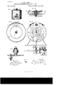
- Figure l is a plan view of a clock which embodies my invention.
- Fig. l is a plan view of parts of said clock-movement and parts of the alarm setting and releasing mechanism.
- Fig. 3 is a vertical section of a clocl-case,its center shaft, and a front elevation of the setting-whcels, the plane of section being indicated by the line of Fig. i).
- Fig. et is avertical section of said clock-case and movement on the line y/ y of Fig. 2, together with a side elevation of the principal parts of an alarm-movein ent underneath the case.
- Fig. C is a transverse section of the connecting-rod and releasingn arm, the plane of section. being indicated by the line ,e .e in Fig. e.
- A designates the clock-case, which is cylindrical in form and contains within it a cloclmovement of a welldinown construction.
- B designates the front plate of this clockmovement, upon the front of which I arrange the alarm setting and releasing mechanism.
- Patent No. 403,274 (lated May 14, 1889.
- dial-wheels viz., the hourwheel-and it is attached to the back end of the hoursocket, while the hour-hand is attached to the front end of said socket, all as in ordinary clockmovements.
- cam-wheel b is mounted so as to slide on the hour-socket, and its teeth correspond with those of the dial-wheel I).
- the pinion t, Fig. 4 meshes into and drives both of the wheels s and b, so that the cam g revolves with the hour-wheel.
- a setting-wheel, C said wheel being provided upon the side which faces the cam g with a trip-pin, 7L, Figs. 2 and 4, said pin also being shown by a broken circle in Fig. 3.
- the hub of this wheel C extends forward through the clock-dial, and is provided with the alarmsetting pointer 7c.
- a setting-button, p upon the side of which is a pinion, fn, that meshes into the teeth of the setting-wheel C, whereby, by turning the setting-button p the alarm-pointer k may be set as desired to bring the pin 7L into position to slip oit the shoulder of the cam g at any predetermined time.
- the cap m is attachably and detachably secured to the elocl-case by means of screws, an opening being left in the top of the clock-case so that the setting button and pinion can be conveniently put in place from the outside.
- the axis of the setting button and pinion is parallel to the center shaft, a, thereby enabling me to thus connect the setting-button with the settingwheel.
- the alarnnstriking mechanism may be of any ordinary construction, and I consider it unnecessary to fully illustrate and describe the same. I prefer to secure this alarm inechanism within the base immediately under the clock, so that its hammer -lever o, Fig. 4, swings upon a vertical pivot, q. Projecting upwardly from a part of the hammerdever is a vertical. connecting-rod, r, that entends up into the clock-case by the side of the holding and releasing arm f. This connecting-rod fr vibrates laterally from right to left when the hammer is oscilla-ted by the alarm-movement.
Landscapes
- Physics & Mathematics (AREA)
- Acoustics & Sound (AREA)
- General Physics & Mathematics (AREA)
- Electromechanical Clocks (AREA)
Description
(No Model.)
A. M. LANE. SETTING MBGHANISM FOR ALARM CLOCKS.
No. 403,274. Patented M3514, 1889.
MMIII.
#WF/7515555. t
(fig/Ma a. ifi-: JAMJ/C 327W j? ZKM f7@ N PETERS. Pmm-Limugupv-Qr. wnmingmmo. C.
f. This spring, at the point where it surrounds UNITED STATES PATENT OEEICE.
ALMERON BI. LANF., OF MERIDFN, CONNECTICIYT.
SPECIFICATION forming part of Letters Application led July 31, 1388.
To all whom it 71mg/ concern.-
Be it known that I, ALMERON M. LANE, a citizen of the United Sta-tes, residing` at Meriden, in the county of New Haven and State of Connecticut, have invented certain new and useful Improvements in. Alarm-Setting Mechanisms, of which the following is a specication.
My invention relates to improvements in alarm-setting mechanisms; and the object of my invention is to simplify the construction, thereby lessening the cost and rendering the parts more convenient to assemble and opcrate.
In the accompanying drawings, Figure l is a plan view of a clock which embodies my invention. Fig. l is a plan view of parts of said clock-movement and parts of the alarm setting and releasing mechanism. Fig. 3 is a vertical section of a clocl-case,its center shaft, and a front elevation of the setting-whcels, the plane of section being indicated by the line of Fig. i). Fig. et is avertical section of said clock-case and movement on the line y/ y of Fig. 2, together with a side elevation of the principal parts of an alarm-movein ent underneath the case. Fig. 5 is a vertical section of the detachable cap with a side elevation of the alarm-setting button and pinion mounted thereon, and Fig. C is a transverse section of the connecting-rod and releasingn arm, the plane of section. being indicated by the line ,e .e in Fig. e.
A designates the clock-case, which is cylindrical in form and contains within it a cloclmovement of a welldinown construction.
B designates the front plate of this clockmovement, upon the front of which I arrange the alarm setting and releasing mechanism.
To the movement-plate B, I secure a peculiar-shaped spring, d, most clearly shown in Fig. 4, which spring extends downwardly around the center shaft, a, and terminates at its lower end in the holdingand releasing arm the center shaft, of, bears against the camwheel h with a constant tendency to press said wheel forward, Upon the front of this cam-wheel Y), I form a sid e-acting cam, g, Figs. 5o 2 and et.
s, Fig. e,
Patent NO. 403,274, (lated May 14, 1889.
Serial No. 281,583. (No model.)
dial-wheels-viz., the hourwheel-and it is attached to the back end of the hoursocket, while the hour-hand is attached to the front end of said socket, all as in ordinary clockmovements. rlhe cam-wheel b is mounted so as to slide on the hour-socket, and its teeth correspond with those of the dial-wheel I). The pinion t, Fig. 4, meshes into and drives both of the wheels s and b, so that the cam g revolves with the hour-wheel.
In front of this cam-wheel l), I arrange a setting-wheel, C, said wheel being provided upon the side which faces the cam g with a trip-pin, 7L, Figs. 2 and 4, said pin also being shown by a broken circle in Fig. 3. The hub of this wheel C extends forward through the clock-dial, and is provided with the alarmsetting pointer 7c. On the upper part of the cloclecase, and pivoted to a lug, Z, on a detachable cap, fm, I arrange a setting-button, p, upon the side of which is a pinion, fn, that meshes into the teeth of the setting-wheel C, whereby, by turning the setting-button p the alarm-pointer k may be set as desired to bring the pin 7L into position to slip oit the shoulder of the cam g at any predetermined time. The cap m is attachably and detachably secured to the elocl-case by means of screws, an opening being left in the top of the clock-case so that the setting button and pinion can be conveniently put in place from the outside.
It should be noticed that the axis of the setting button and pinion is parallel to the center shaft, a, thereby enabling me to thus connect the setting-button with the settingwheel.
The alarnnstriking mechanism may be of any ordinary construction, and I consider it unnecessary to fully illustrate and describe the same. I prefer to secure this alarm inechanism within the base immediately under the clock, so that its hammer -lever o, Fig. 4, swings upon a vertical pivot, q. Projecting upwardly from a part of the hammerdever is a vertical. connecting-rod, r, that entends up into the clock-case by the side of the holding and releasing arm f. This connecting-rod fr vibrates laterally from right to left when the hammer is oscilla-ted by the alarm-movement. Then the pin 7L bears upon the plain face of the cam g, the holding and releasing arm f of IOC the spring d is held Within the path of the rod r, as most clearly shown in Fig. 6, so that said hamm er-lever is held and prevented from operating. When thel time-movement indicates the time for which the alarm is set, the pin h slips off the shoulder' of the cam g, thereby throwing the holding and releasing arm f forward out of the path of the rod r on the hammer-lever, as indicated by the broken lines in Fig. 6, so that the hammerflever is released and free to operate under the influence 0f the alarm-movement.
I claim as my inventionl. In an alarm-clock, the combination of the shouldered cam g, revolving With the hourwheel and sliding on the hour-socket, the set- ALMERON M. LANE.
Witnesses:
' JAMES SHEPARD,
JOHN EDWARDS, Jr.
Publications (1)
| Publication Number | Publication Date |
|---|---|
| US403274A true US403274A (en) | 1889-05-14 |
Family
ID=2472225
Family Applications (1)
| Application Number | Title | Priority Date | Filing Date |
|---|---|---|---|
| US403274D Expired - Lifetime US403274A (en) | Setting mechanism for alarm-clocks |
Country Status (1)
| Country | Link |
|---|---|
| US (1) | US403274A (en) |
-
0
- US US403274D patent/US403274A/en not_active Expired - Lifetime
Similar Documents
| Publication | Publication Date | Title |
|---|---|---|
| US403274A (en) | Setting mechanism for alarm-clocks | |
| US390786A (en) | Alarm-clock | |
| US555387A (en) | Clock | |
| US329078A (en) | Heney l | |
| US248935A (en) | Striking mechanism of repeating-clocks | |
| US775010A (en) | Intermittent-alarm clock. | |
| US391802A (en) | Alarm-clock | |
| US377558A (en) | Mechanism | |
| US577573A (en) | Timepiece-dial | |
| US293589A (en) | Striking mechanism for eight | |
| US348981A (en) | Calendar-clock | |
| US1110714A (en) | Intermittent and long alarm clock. | |
| US611733A (en) | Ferdinand gundorpii | |
| US461315A (en) | Striking mechanism for clocks | |
| US220540A (en) | Improvement in alarm-clocks | |
| US376074A (en) | Clock striking mechanism | |
| US457024A (en) | Repeating mechanism for clocks | |
| US208563A (en) | Improvement in clock-cases | |
| US546103A (en) | Alarm-clock | |
| US596146A (en) | Eight-day alarm-clock | |
| US237532A (en) | Striking mechanism for clocks | |
| US473424A (en) | Calendar-clock | |
| US919765A (en) | Alarm-clock. | |
| US1181557A (en) | Alarm-clock. | |
| US528739A (en) | Half to frederick n |