US4029967A - Device for the uniform irradiation of goods by means of electro-magnetic radiation - Google Patents
Device for the uniform irradiation of goods by means of electro-magnetic radiation Download PDFInfo
- Publication number
- US4029967A US4029967A US05/526,187 US52618774A US4029967A US 4029967 A US4029967 A US 4029967A US 52618774 A US52618774 A US 52618774A US 4029967 A US4029967 A US 4029967A
- Authority
- US
- United States
- Prior art keywords
- goods
- radiation
- irradiated
- radiation source
- receiving
- Prior art date
- Legal status (The legal status is an assumption and is not a legal conclusion. Google has not performed a legal analysis and makes no representation as to the accuracy of the status listed.)
- Expired - Lifetime
Links
Images


Classifications
-
- G—PHYSICS
- G21—NUCLEAR PHYSICS; NUCLEAR ENGINEERING
- G21K—HANDLING OF PARTICLES OR IONISING RADIATION NOT OTHERWISE PROVIDED FOR; IRRADIATION DEVICES; GAMMA RAY OR X-RAY MICROSCOPES
- G21K5/00—Irradiation devices
- G21K5/02—Irradiation devices having no beam-forming means
-
- A—HUMAN NECESSITIES
- A61—MEDICAL OR VETERINARY SCIENCE; HYGIENE
- A61L—METHODS OR APPARATUS FOR STERILISING MATERIALS OR OBJECTS IN GENERAL; DISINFECTION, STERILISATION OR DEODORISATION OF AIR; CHEMICAL ASPECTS OF BANDAGES, DRESSINGS, ABSORBENT PADS OR SURGICAL ARTICLES; MATERIALS FOR BANDAGES, DRESSINGS, ABSORBENT PADS OR SURGICAL ARTICLES
- A61L2/00—Disinfection or sterilisation of materials or objects, in general; Accessories therefor
- A61L2/02—Disinfection or sterilisation of materials or objects, in general; Accessories therefor using physical processes
- A61L2/08—Radiation
-
- G—PHYSICS
- G21—NUCLEAR PHYSICS; NUCLEAR ENGINEERING
- G21F—PROTECTION AGAINST X-RADIATION, GAMMA RADIATION, CORPUSCULAR RADIATION OR PARTICLE BOMBARDMENT; TREATING RADIOACTIVELY CONTAMINATED MATERIAL; DECONTAMINATION ARRANGEMENTS THEREFOR
- G21F5/00—Transportable or portable shielded containers
- G21F5/02—Transportable or portable shielded containers with provision for restricted exposure of a radiation source within the container
- G21F5/04—Means for controlling exposure, e.g. time, size of aperture
Definitions
- This invention relates to a device for the uniform irradiation of goods by means of electro-magnetic radiation having a quantum energy larger than 5 KeV.
- Short-wave electro-magnetic radiation changes the physical, chemical and biological characteristics of materials.
- the radiation is applied in particular in the extinction of micro-organisms.
- Objects to be irradiated may include, for example, injection syringes, scalpels, suture material, feedstuffs, food for humans and enzymic systems. This is often done in packages ready for shipment. A certain minimum dosage practically ensures sterility. Further irradiation would usually only injure the goods to be irradiated. In the technically common sizes of recipients in which the goods are normally treated, the spreading of the radiation and its absorption are the reasons why not every volume element receives the same dosage of irradiation.
- overdosing ratio the relationship of largest dosage to smallest dosage in a certain material to be irradiated, e.g. irradiation containers like a cardboard box or a barrel, is called "overdosing ratio". Uniform irradiation means that the overdosing ratio will be close to 1.
- device A There is a device known from the ATOMIC ENERGY OF CANADA LIMITED (in the following called "device A”), in which a number of cardboard boxes containing the goods to be irradiated and placed horizontally in two layers move around a 60 Co radiation source in the shape of a 1 m 2 sized table in such a way that the cardboard boxes are radiated from two opposite sides.
- the cardboard boxes have to be turned after one half of the envisaged irradiation time has passed or the position of the track has to be changed.
- the overdosing ratio rises, e.g. for cardboard boxes of a size of 55.2 cm ⁇ 43.2 cm ⁇ 91.4 cm and a medium filling density (or packing density) of 0.3 g/cm 3 , to values already too high for many applications.
- Another device of the RADIATION DYNAMICS LIMITED (in the following called “device R") operates on the principle that six containers rotate on a circular path of 2.2 m in diameter around a 60 Co rod-type source of approximately 45 cm length which moves up and down.
- the ashlar-type containers have each a square base and turn in the same direction around their axes. Rotation takes place in steps of 90°, so that practically one flat side is always directed towards the radiation source.
- the overdosing ratio with a given container size of for example 70 cm ⁇ 70 cm ⁇ 250 cm and a filling density of 0.7 g/cm 3 is larger than 2.
- German patent specification 1.953,135 describes a device which operates on the basis of a radiation source having the shape of a table.
- a fadeout device consisting of prismatic rods leads to an improvement, as far as the decrease in dosage capacity with increasing distance normal to the radiation source is concerned. Otherwise this result is obtained only by means of a considerably larger plate-shaped radiation source.
- a somewhat more uniform irradiation always means that a reduced radiation efficiency has to be put up with, due to the prismatic rods.
- the device according to the invention it is not endeavoured to create a homogeneous field of radiation in air.
- the field of radiation is intentionally considerably distorted, i.e., it is made more inhomogeneous.
- the goods to be irradiated are receiving the same radiation dosage in each volume element, which means there will be no dosage minimum in the center.
- a device of the type mentioned above which comprises at least one radiation source and means for the reception of goods to be irradiated at least one shielding element is arranged laterally of the radiation path from the radiation source and the center axis of the goods in such a manner that the shielding effect of the shielding element increases with increasing lateral space from the radiation path, radiation source, the shielding element and the means for the reception of the goods to be irradiated are arranged to allow for the radiation to enter the goods through the entire superficies thereof in such a way that the region immediately around the center axis of the goods is irradiated without radiation being affected by the shielding element.
- the shielding element laterally of the radiation path from the radiation source and the center axis of the goods to be irradiated ensures that in a cross section normal to the center axis of the goods, the dosage reached will be equal. If the goods are very large, it is recommended to arrange two shielding elements symmetrically on both sides of the radiation path. However, one source of radiation is sufficient, when the means for the reception of the goods are rotatably mounted.
- the goods to be irradiated rotate around their own axis, e.g. the axis of symmetry, or the radiation source and the lateral shielding element turn around the goods.
- a uniform irradiation of the cross section of the goods may also be obtained by grouping several radiation sources with their pertaining lateral shielding elements in the form of e.g. a circle around the goods which arrangement does not contain any moving parts.
- a radiation source for X-rays is understood to be the place where the X-rays are produced.
- center axis of the goods means a rotating axis in the case of the turnable arrangement, and in the case of the static arrangement the crossing line of the beams of rays emitted from the various radiation sources and passing unhindered through the gap left by the shielding elements arranged laterally.
- the center axis of the goods coincides with the longest axis of symmetry of the goods.
- the means for the reception of the goods are mounted so as to be movable in the direction of the center axis of the goods.
- the barrels rotate around their own axes and are passed with the aid of a conveyor belt in close sequence and with constant velocity past the radiation source.
- OPtimum use of radiation is obtained when several devices of this type surround the radiation source (or a beam of individual radiation sources) in the form of a circle. Only when changing over to a new charge of goods which does not correspond with the previous charge in density or irradiation dosage, irradiation will not be uniform for the first barrel.
- Another possibility of obtaining uniform irradiation consists in arranging the radiation source and means for the reception of the radiation source and of the goods in such a way that the immission of rays in the central field between the axial ends of the goods is reduced.
- This reduction can be attained by setting up a long source of radiation standing preferably parallel to the center axis of the goods (e.g. longest axis of symmetry) so that the quantity of activity per unit of length will be smaller in the central region than opposite the axial ends of the goods, or that the center is shielded better than the ends.
- This shielding may consist in a reinforcement of the amoring surrounding the radiation source or of the container wall where and if the goods are placed in a container.
- the container will have the shape of a barrel.
- the means for the reception of the radiation source and of the goods are equally suitable for the reduction of the useful radiation immission, if these permit to move a radiation source, which is geometrically small when compared with the dimensions of the goods, with respect to the center axis of the goods in such a manner that the exposure time for each unit of length of the axis of motion during one radiation cycle, which in this context may also mean "moving cycle", is smaller in the central field than in the space opposite the axial ends of the goods to be irradiated.
- the exposure time has to be changed only at the beginning and at the end of a new charge.
- the goods to be irradiated must be irradiated from all sides. As described above, this can be achieved by turning the goods or by having the radiation source turn around the goods to be irradiated. The same effect is also obtained if several radiation sources are arranged around the goods.
- the external container shape recommended is preferably a cylinder.
- a container of square cross section is introduced whose inner space contains the goods to be irradiated.
- the space between cylinder and inner space is filled with material of the same filling density as the goods to be irradiated.
- the device according to the invention enables the uniform irradiation of large volumes, e.g. cylinders of more than 1 m in diameter, and of high filling density goods, e.g. 1 g/cm 3 .
- This has a considerable effect of technical rationalization, besides the considerable improvement in the quality of the goods, since nowaday there is a tendency to use larger packaging and shipping units (containers), and for these the device is easily adaptable.
- X-ray equipments with low operating voltage and simple radiation protection may now be used also for considerably larger sizes of containers for goods to be irradiated, whenever short exposure time is important, or where the weight of the equipment should low, e.g. in non-stationary equipment.
- the device according to the invention may also be used to improve the efficiency of the radiation (see also example), because the lateral shielding elements only reduce the radiation dosage, which, e.g. in the case of sterilization, is anyhow unnecessary; and because the axial ends of the goods, i.e., the usually underirradiated places to which, however, the minimum dosage refers, are brought up to the general dosage level needing a little more radiation only.
- FIG. 1 is an elevational view of a device according to the invention
- FIG. 2 is a top view of FIG. 1;
- FIG. 3 is a top plan view of another embodiment for the irradiation of goods in containers having each a square base;
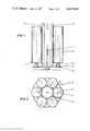
- FIG. 4 is a similar view of still another embodiment having several radiation sources and a uniformly irradiated inner space, said embodiment comprising no moving parts;
- FIG. 5 is a diagram showing the influence of filling density on the overdosing ratio
- FIGS. 6 and 7 are diagrams showing the efficiency of rays as a function of the filling density by means of various examples.
- goods 2 to be irradiated are accommodated in six preferably cylindrical containers arranged in circular form around a rod-type radioactive radiation source 1.
- the containers are placed on a plate-shaped base and are moved in the same direction or preferably in opposite directions by means of a gear drive 3.
- the rotary plate shaft 4 should be a thin-walled hollow shaft. If necessary, the equipment can also be provided for goods hanging vertically.
- shielding elements 5 Radiation which does not focus directly onto the center axis of the goods, is diminished increasingly with growing lateral space, by means of suitable shielding elements 5.
- the shielding elements 5 of each two neighboring containers are expediently combined to form a unit.
- the shielding elements 5 have to be adapted to the filling density of the goods and to the geometrical conditions involved. By this arrangement a uniform irradiation in a plane normal to the container axis is obtained.
- the preferably short rod-shaped radiation source 1 is moved in axial direction, parallel to the container axis, so that the exposure time per longitudinal unit -- on a time average over one radiation cycle -- is reduced in the central field, relatively to the end positions (in FIG. 1 denoted by 6 and 7), in the range opposite the container ends.
- the source may be moved either continuously or step-by-step. This movement of the radiation source has to be optimized according to the container size and to the filling density of the goods.
- the containers of the goods to be irradiated together with the shielding elements 5 on a revolving disc 8 making a revolving or pendulum movement.
- a revolving disc 8 facilitates the charging and discharging of the goods 2 to be irradiated.
- the goods 2 may also consist of smaller units placed on top of each other or side by side.
- FIG. 4 shows an embodiment which has no moving parts.
- a number of rod-shaped radiation sources 1 are arranged around the goods 2 to be irradiated.
- the goods 2 have the shape of a cylinder.
- two shielding elements 5 are associated with each radiation source.
- each two neighboring shielding elements 5 are combined to form a unit.
- the rod-shaped radiation sources 1 are somewhat longer than the cylinder-shaped goods and have at their ends more active quantity per longitudinal unit than in the central field.
- the beam of electrons is guided analogous to the activity distribution so that at the ends a higher capacity is absorbed in the anode than in the central field.
- Efficiency of radiation means the portion of gamma radiation energy absorbed by the goods to be irradiated as compared with the amount of gamma radiation energy emitted from the nuclide.
- the portion of gamma radiation energy not used contains: self-absorption of the radioactive emitter, absorption of the source-capsule and other attachments, and the portion of radiation not utilizable for geometrical reasons.
- the following examples show that in the device according to the invention the self-absorption and the absorption in the material belonging to the radiation source is assumed to amount to 26%, normal to the radiation source axis.
- the rates in device R according to the state of the art can be regarded under the same aspects.
- FIGS. 1 and 2 As indicated in FIGS. 1 and 2, six cylindrical containers for goods to be irradiated are arranged around a rod-shaped 60 Co radiation source 46 cm in active length and 3 cm in diameter on a divided circle of 1 m in diameter.
- the thinplate containers for the goods have a diameter of 45 cm and a height of 200 cm, and are filled with fodder (filling density 0.7 g/cm 3 ). In practice three small containers will often be placed one on top of the other.
- the containers are placed on revolving plates which turn in opposite directions and are each mounted on a rotary plate shaft of thin-walled material.
- the space between the drive of the revolving plate and the support should not be smaller than about 10 cm.
- the lateral shielding elements are made of angle-iron in the shape illustrated.
- the outer angle-iron length is 14 cm, the maximum angle thickness is 2.4 cm.
- the inner angles are pointed and slightly concave, with a bending radius of 43 cm. They are arranged as shown in FIGS. 1 and 2, with the distance of the axis of the radiation source up to the 90° angle edge being 32 cm.
- the containers for the goods to be irradiated and the shielding elements are placed on a revolving disc which moves around the axis of the radiation source.
- the radiation source is driven step by step by means of a lifting gear, whereby 12 positions, at a distance of 16.7 cm each, are being approached one after the other beginning from the bottom. In the final positions opposite the container ends the radiation source has an exposure time longer than that at the other radiation source positions by a factor of 2.8.
- Several moving cycles may be applied within one radiation cycle.
- the overdosing ratio 10 in the goods to be irradiated is 1.04 (see curve H o in FIG. 5), the radiation efficiency 12 is 19%; (see
- Example 1a The device according to the invention in Example 1a) (container diameter 45 cm) is approximately comparable with the box dimensions 55.2 cm ⁇ 43.2 cm ⁇ 91.4 cm of the device A according to the state of the art, the value 43.2 cm standing for the thickness to be penetrated.
- the radiation utilization (FIG. 6, curve A) is very advantageous, the overdosing ratio with the filling density 11 of 0.7 g/cm 3 considered is intolerably high (FIG. 5, curve A). With the device according to the invention this material could be uniformly irradiated, even in containers with a diameter of 1.4 m.
- the side edge has a distance of 48.5 cm from the axis of the source.
- the same arrangement is used for the radiation source as described in connection with Example 1a). Here twelve positions are approached, too. The strongest point of the radiation source is in the two end positions opposite the container ends. The exposure time in these end positions is higher than in the other positions by a factor of 3.6.
- the overdosing ratio 10 is 1.3 (curve H q in FIG. 5).
- the radiation efficiency 12 is 18% (curve H q in FIG. 7).
- Example 2a is directly comparable with the device R according to the state of the art, since in both cases the same type of container and the same size of radiation container is used. According to curve R in FIG. 5 the overdosing ratio 10 in device R reaches already a value of 2.1 with the filling density 11 of 0.7 g/cm 3 . The radiation efficiency 12 is about 13% (see curve R in FIG. 7)-.
- Example 2a) From the results of Examples 2a) and 2c) it arises clearly that the device according to the invention represents an essential technological progress, as far as the efficiency of radiation and mainly the overdosing ratio is concerned.
- the low overdosing ratio of the device according to the invention as in Example 2a) is reached in that the radiation source opposite the container ends emits a higher radiation quantity (compare also table 1, section I to section II), and that in the device according to the invention shielding elements and continuous container rotation are used (see section III).
- Section I corresponds to the well-known device R.
- Section III corresponds to the device according to the invention as in Example 2a).
Landscapes
- Physics & Mathematics (AREA)
- Engineering & Computer Science (AREA)
- General Engineering & Computer Science (AREA)
- High Energy & Nuclear Physics (AREA)
- Health & Medical Sciences (AREA)
- Epidemiology (AREA)
- Life Sciences & Earth Sciences (AREA)
- Animal Behavior & Ethology (AREA)
- General Health & Medical Sciences (AREA)
- Public Health (AREA)
- Veterinary Medicine (AREA)
- Apparatus For Disinfection Or Sterilisation (AREA)
- Treatments Of Macromolecular Shaped Articles (AREA)
- Physical Or Chemical Processes And Apparatus (AREA)
- Analysing Materials By The Use Of Radiation (AREA)
- Particle Accelerators (AREA)
Applications Claiming Priority (2)
| Application Number | Priority Date | Filing Date | Title |
|---|---|---|---|
| DT2358652 | 1973-11-24 | ||
| DE2358652A DE2358652C3 (de) | 1973-11-24 | 1973-11-24 | Bestrahlungsvorrichtung zur gleichmäßigen Bestrahlung von Bestrahlungsgut mittels elektromagnetischer Strahlung von mehr als 5 keV Energie |
Publications (1)
| Publication Number | Publication Date |
|---|---|
| US4029967A true US4029967A (en) | 1977-06-14 |
Family
ID=5898991
Family Applications (1)
| Application Number | Title | Priority Date | Filing Date |
|---|---|---|---|
| US05/526,187 Expired - Lifetime US4029967A (en) | 1973-11-24 | 1974-11-22 | Device for the uniform irradiation of goods by means of electro-magnetic radiation |
Country Status (6)
| Country | Link |
|---|---|
| US (1) | US4029967A (de) |
| CA (1) | CA1026016A (de) |
| CH (1) | CH581895A5 (de) |
| DE (1) | DE2358652C3 (de) |
| FR (1) | FR2252633B1 (de) |
| GB (1) | GB1472437A (de) |
Cited By (22)
| Publication number | Priority date | Publication date | Assignee | Title |
|---|---|---|---|---|
| US4101766A (en) * | 1976-01-10 | 1978-07-18 | Tokyo Shibaura Electric Co., Ltd. | X-ray image intensifier photofluorography apparatus for correcting the brightness of the output image |
| US4118624A (en) * | 1976-05-05 | 1978-10-03 | Ionit Anstalt Bernhad Berghaus | Frame for the support of articles which are to be treated |
| FR2410503A1 (fr) * | 1977-12-01 | 1979-06-29 | Sulzer Ag | Dispositif d'irradiation de produits fluants, en particulier d'aliments granulaires du betail et analogues |
| US4193204A (en) * | 1978-12-11 | 1980-03-18 | American Can Company | Ultraviolet light curing apparatus for containers and the like |
| EP0105580A3 (de) * | 1982-09-30 | 1985-09-18 | Radiation Dynamics Inc. | Bestrahlungsvorrichtung für zylindrische Artikel |
| US5001352A (en) * | 1985-09-23 | 1991-03-19 | Tetzlaff Karl H | Method and apparatus for irradiating objects with ionizing radiation |
| US5107524A (en) * | 1989-03-20 | 1992-04-21 | Hitachi, Ltd. | Synchrotron radiation utilizing apparatus and method for utilizing synchrotron radiation |
| US5400382A (en) * | 1992-04-19 | 1995-03-21 | Alpha Omega Technologies, Inc. | Automated irradiator for the processing of products and a method of operation |
| US6180951B1 (en) * | 1999-08-06 | 2001-01-30 | Nutek Corporation | Process for irradiation producing constant depth/dose profile |
| US6274100B1 (en) * | 1998-11-05 | 2001-08-14 | J.L. Shepherd & Associated | Process irradiator |
| US20010028041A1 (en) * | 2000-03-03 | 2001-10-11 | Hubbard Neil Trevor | Irradiation apparatus |
| WO2002075771A1 (en) * | 2001-03-20 | 2002-09-26 | Advanced Electron Beams, Inc. | X-ray irradiation apparatus |
| US6504898B1 (en) | 2000-04-17 | 2003-01-07 | Mds (Canada) Inc. | Product irradiator for optimizing dose uniformity in products |
| US20030076928A1 (en) * | 2001-10-22 | 2003-04-24 | Hansen Timothy B. | Irradiation apparatus and method |
| US20050031077A1 (en) * | 2001-03-20 | 2005-02-10 | Advanced Electron Beams, Inc. | X-ray irradiation apparatus |
| US20080273661A1 (en) * | 2007-05-05 | 2008-11-06 | Kirk Randol E | Irradiation method and apparatus |
| ITTO20100650A1 (it) * | 2010-07-28 | 2012-01-29 | Gilardoni Spa | Apparecchiatura per il trattamento di materiali con radiazioni ionizzanti. |
| FR3006592A1 (fr) * | 2013-06-10 | 2014-12-12 | L B A Consulting | Dispositif de decontamination pour materiel medical |
| CN111803735A (zh) * | 2020-07-10 | 2020-10-23 | 珠海丽珠试剂股份有限公司 | 一种血液辐照处理方法及血液辐照仪 |
| WO2022105346A1 (zh) * | 2020-11-19 | 2022-05-27 | 周星 | 新冠病毒灭菌消毒装置及灭菌方法 |
| JP2023070232A (ja) * | 2021-11-09 | 2023-05-19 | 株式会社クォンタムフラワーズ&フーズ | 中性子線被照射装置 |
| US11980148B2 (en) | 2021-07-29 | 2024-05-14 | Quantum Flowers & Foods Co., Ltd. | Neutron ray irradiation target apparatus, mutation induction method, and irradiation target manufacturing method |
Families Citing this family (6)
| Publication number | Priority date | Publication date | Assignee | Title |
|---|---|---|---|---|
| DE2754463C3 (de) * | 1977-12-07 | 1981-12-17 | Gebrüder Sulzer AG, 8401 Winterthur | Vorrichtung zum Bestrahlen fließbaren Gutes, insbesondere körniger Futtermittel u.ä. |
| FR2498876A1 (fr) * | 1981-02-04 | 1982-08-06 | Novatome Ind | Dispositif d'irradiation de produits agricoles, sur les lieux de production |
| DE3533826A1 (de) * | 1985-09-23 | 1987-04-02 | Tetzlaff Karl Heinz | Verfahren zur bestrahlung grosser bestrahlungsguteinheiten mittels ionisierender strahlung |
| DE19650845A1 (de) * | 1996-11-27 | 1998-05-28 | Gamma Service Produktbestrahlu | Sicherheitssystem für Produktbestrahlungsanlagen |
| CN112366021B (zh) * | 2020-11-09 | 2022-09-23 | 中国工程物理研究院核物理与化学研究所 | 一种实现反应堆辐照参数均匀化的设备及方法 |
| CN113304285A (zh) * | 2021-05-21 | 2021-08-27 | 中核同辐(长春)辐射技术有限公司 | 一种冷加工物理灭菌用辐照消杀装置及其操作方法 |
Citations (1)
| Publication number | Priority date | Publication date | Assignee | Title |
|---|---|---|---|---|
| US3496362A (en) * | 1965-10-21 | 1970-02-17 | Ca Atomic Energy Ltd | Apparatus for irradiating objects with selected uniform doses of radiation |
-
1973
- 1973-11-24 DE DE2358652A patent/DE2358652C3/de not_active Expired
-
1974
- 1974-11-15 CH CH1522874A patent/CH581895A5/xx not_active IP Right Cessation
- 1974-11-20 GB GB5024374A patent/GB1472437A/en not_active Expired
- 1974-11-21 FR FR7438231A patent/FR2252633B1/fr not_active Expired
- 1974-11-22 US US05/526,187 patent/US4029967A/en not_active Expired - Lifetime
- 1974-11-25 CA CA214,517A patent/CA1026016A/en not_active Expired
Patent Citations (1)
| Publication number | Priority date | Publication date | Assignee | Title |
|---|---|---|---|---|
| US3496362A (en) * | 1965-10-21 | 1970-02-17 | Ca Atomic Energy Ltd | Apparatus for irradiating objects with selected uniform doses of radiation |
Cited By (36)
| Publication number | Priority date | Publication date | Assignee | Title |
|---|---|---|---|---|
| US4101766A (en) * | 1976-01-10 | 1978-07-18 | Tokyo Shibaura Electric Co., Ltd. | X-ray image intensifier photofluorography apparatus for correcting the brightness of the output image |
| US4118624A (en) * | 1976-05-05 | 1978-10-03 | Ionit Anstalt Bernhad Berghaus | Frame for the support of articles which are to be treated |
| FR2410503A1 (fr) * | 1977-12-01 | 1979-06-29 | Sulzer Ag | Dispositif d'irradiation de produits fluants, en particulier d'aliments granulaires du betail et analogues |
| US4193204A (en) * | 1978-12-11 | 1980-03-18 | American Can Company | Ultraviolet light curing apparatus for containers and the like |
| EP0105580A3 (de) * | 1982-09-30 | 1985-09-18 | Radiation Dynamics Inc. | Bestrahlungsvorrichtung für zylindrische Artikel |
| US5001352A (en) * | 1985-09-23 | 1991-03-19 | Tetzlaff Karl H | Method and apparatus for irradiating objects with ionizing radiation |
| US5107524A (en) * | 1989-03-20 | 1992-04-21 | Hitachi, Ltd. | Synchrotron radiation utilizing apparatus and method for utilizing synchrotron radiation |
| US5400382A (en) * | 1992-04-19 | 1995-03-21 | Alpha Omega Technologies, Inc. | Automated irradiator for the processing of products and a method of operation |
| US6274100B1 (en) * | 1998-11-05 | 2001-08-14 | J.L. Shepherd & Associated | Process irradiator |
| US6180951B1 (en) * | 1999-08-06 | 2001-01-30 | Nutek Corporation | Process for irradiation producing constant depth/dose profile |
| WO2001011634A1 (en) * | 1999-08-06 | 2001-02-15 | Nutek Corporation | Process for irradiation producing constant depth/dose profile |
| US20010028041A1 (en) * | 2000-03-03 | 2001-10-11 | Hubbard Neil Trevor | Irradiation apparatus |
| US6900445B2 (en) * | 2000-03-03 | 2005-05-31 | Ingleby (1472) Limited | Irradiation apparatus |
| US6504898B1 (en) | 2000-04-17 | 2003-01-07 | Mds (Canada) Inc. | Product irradiator for optimizing dose uniformity in products |
| US20050031077A1 (en) * | 2001-03-20 | 2005-02-10 | Advanced Electron Beams, Inc. | X-ray irradiation apparatus |
| US6738451B2 (en) | 2001-03-20 | 2004-05-18 | Advanced Electron Beams, Inc. | X-ray irradiation apparatus |
| US20020154740A1 (en) * | 2001-03-20 | 2002-10-24 | Advanced Electron Beams, Inc. | X-ray irradiation apparatus |
| WO2002075771A1 (en) * | 2001-03-20 | 2002-09-26 | Advanced Electron Beams, Inc. | X-ray irradiation apparatus |
| US7133493B2 (en) | 2001-03-20 | 2006-11-07 | Advanced Electron Beams, Inc. | X-ray irradiation apparatus |
| US20070071167A1 (en) * | 2001-03-20 | 2007-03-29 | Tzvi Avnery | X-ray irradiation apparatus |
| US7324630B2 (en) | 2001-03-20 | 2008-01-29 | Advanced Electron Beams, Inc. | X-ray irradiation apparatus |
| US20030076928A1 (en) * | 2001-10-22 | 2003-04-24 | Hansen Timothy B. | Irradiation apparatus and method |
| US6763085B2 (en) | 2001-10-22 | 2004-07-13 | Cleaner Food, Inc. | Irradiation apparatus and method |
| US20080273661A1 (en) * | 2007-05-05 | 2008-11-06 | Kirk Randol E | Irradiation method and apparatus |
| US7515686B2 (en) * | 2007-05-05 | 2009-04-07 | Kirk Randol E | Irradiation method and apparatus |
| ITTO20100650A1 (it) * | 2010-07-28 | 2012-01-29 | Gilardoni Spa | Apparecchiatura per il trattamento di materiali con radiazioni ionizzanti. |
| EP2412388A1 (de) * | 2010-07-28 | 2012-02-01 | GILARDONI S.p.A. | Geräte zur Behandlung von Materialien mit ionisierenden Strahlungen |
| FR3006592A1 (fr) * | 2013-06-10 | 2014-12-12 | L B A Consulting | Dispositif de decontamination pour materiel medical |
| WO2014199058A1 (fr) * | 2013-06-10 | 2014-12-18 | L.B.A. Consulting | Dispositif de décontamination pour matériel médical |
| US9750831B2 (en) | 2013-06-10 | 2017-09-05 | L.B.A. Consulting | Decontamination device for medical material |
| RU2659722C2 (ru) * | 2013-06-10 | 2018-07-03 | Л.Б.А. Консалтинг | Устройство для деконтаминации медицинского оборудования |
| CN111803735A (zh) * | 2020-07-10 | 2020-10-23 | 珠海丽珠试剂股份有限公司 | 一种血液辐照处理方法及血液辐照仪 |
| CN111803735B (zh) * | 2020-07-10 | 2023-02-14 | 珠海丽珠试剂股份有限公司 | 一种血液辐照处理方法及血液辐照仪 |
| WO2022105346A1 (zh) * | 2020-11-19 | 2022-05-27 | 周星 | 新冠病毒灭菌消毒装置及灭菌方法 |
| US11980148B2 (en) | 2021-07-29 | 2024-05-14 | Quantum Flowers & Foods Co., Ltd. | Neutron ray irradiation target apparatus, mutation induction method, and irradiation target manufacturing method |
| JP2023070232A (ja) * | 2021-11-09 | 2023-05-19 | 株式会社クォンタムフラワーズ&フーズ | 中性子線被照射装置 |
Also Published As
| Publication number | Publication date |
|---|---|
| GB1472437A (en) | 1977-05-04 |
| CH581895A5 (de) | 1976-11-15 |
| DE2358652C3 (de) | 1979-07-19 |
| DE2358652A1 (de) | 1975-05-28 |
| CA1026016A (en) | 1978-02-07 |
| FR2252633A1 (de) | 1975-06-20 |
| FR2252633B1 (de) | 1979-03-16 |
| DE2358652B2 (de) | 1978-11-09 |
Similar Documents
| Publication | Publication Date | Title |
|---|---|---|
| US4029967A (en) | Device for the uniform irradiation of goods by means of electro-magnetic radiation | |
| US5001352A (en) | Method and apparatus for irradiating objects with ionizing radiation | |
| US7187752B2 (en) | Product irradiator for optimizing dose uniformity in products | |
| US5461656A (en) | Microwave X-ray source and methods of sterilization | |
| US6285030B1 (en) | Article irradiation system in which article transporting conveyor is closely encompassed by shielding material | |
| CN103762007B (zh) | 电子直线加速器二维扫描高能x线辐照系统 | |
| CN116761552A (zh) | 辐照设备 | |
| US7145155B2 (en) | Process for electron sterilization of a container | |
| US7486771B2 (en) | Process and apparatus for irradiating product pallets or containers | |
| US7289600B2 (en) | Apparatus and process for irradiating product pallets | |
| CN203689930U (zh) | 电子直线加速器二维扫描高能x线辐照系统 | |
| US3411002A (en) | Apparatus for irradiating goods during movement past a radioactive source mounted ina shield enclosure | |
| US7197111B2 (en) | Process and apparatus for irradiating product pallets | |
| US20230390433A1 (en) | An irradiation apparatus | |
| US2858441A (en) | Method of increasing the uniformity of dose produced by a beam of high energy electrons throughout the volume of objects irradiated thereby | |
| EP1459770A1 (de) | Verfahren und Vorrichtung zur Bestrahlung von Produkten auf Paletten | |
| Deeley | A basic interpretation of the technical language of radiation processing | |
| US6885013B2 (en) | System for, and method of, irradiating articles | |
| Ley | Technological aspects of food irradiation with particular reference to Salmonellae elimination | |
| WO1986002771A1 (en) | Irradiation processing system with dynamic source scan | |
| Krishnamurthy et al. | Design considerations for food irradiators in developing countries | |
| Grünewald et al. | Experiences in the operation of food irradiation facilities | |
| Lazurik et al. | Comparison of product irradiation technology on industrial X-ray radiation facility | |
| Crowley-Milling | The application of irradiation in industry |