US4013023A - Incineration method and system - Google Patents
Incineration method and system Download PDFInfo
- Publication number
- US4013023A US4013023A US05/645,063 US64506375A US4013023A US 4013023 A US4013023 A US 4013023A US 64506375 A US64506375 A US 64506375A US 4013023 A US4013023 A US 4013023A
- Authority
- US
- United States
- Prior art keywords
- afterburner
- furnace
- temperatures
- temperature
- predetermined
- Prior art date
- Legal status (The legal status is an assumption and is not a legal conclusion. Google has not performed a legal analysis and makes no representation as to the accuracy of the status listed.)
- Expired - Lifetime
Links
- 238000000034 method Methods 0.000 title claims 20
- QVGXLLKOCUKJST-UHFFFAOYSA-N atomic oxygen Chemical compound [O] QVGXLLKOCUKJST-UHFFFAOYSA-N 0.000 claims abstract description 52
- 239000001301 oxygen Substances 0.000 claims abstract description 52
- 229910052760 oxygen Inorganic materials 0.000 claims abstract description 52
- 230000003247 decreasing effect Effects 0.000 claims abstract description 36
- 239000007789 gas Substances 0.000 claims abstract description 33
- 239000010815 organic waste Substances 0.000 claims abstract description 15
- 230000003647 oxidation Effects 0.000 claims abstract description 12
- 238000007254 oxidation reaction Methods 0.000 claims abstract description 12
- 239000002699 waste material Substances 0.000 claims abstract 19
- 239000000126 substance Substances 0.000 claims abstract 15
- 230000001105 regulatory effect Effects 0.000 claims abstract 13
- 230000002950 deficient Effects 0.000 claims abstract 7
- 238000012544 monitoring process Methods 0.000 claims description 69
- 239000000446 fuel Substances 0.000 claims description 58
- 238000004891 communication Methods 0.000 claims description 16
- 230000007423 decrease Effects 0.000 claims description 13
- 230000009471 action Effects 0.000 claims description 12
- 239000010801 sewage sludge Substances 0.000 claims description 12
- 230000002441 reversible effect Effects 0.000 claims description 7
- 238000002485 combustion reaction Methods 0.000 claims description 6
- 238000000197 pyrolysis Methods 0.000 claims 6
- 230000000171 quenching effect Effects 0.000 abstract description 14
- 238000010791 quenching Methods 0.000 abstract description 11
- 230000007812 deficiency Effects 0.000 abstract description 4
- 230000000694 effects Effects 0.000 description 7
- 239000010802 sludge Substances 0.000 description 6
- 239000004020 conductor Substances 0.000 description 4
- 239000000567 combustion gas Substances 0.000 description 3
- 239000000523 sample Substances 0.000 description 3
- 238000010586 diagram Methods 0.000 description 2
- 235000003642 hunger Nutrition 0.000 description 2
- 239000000463 material Substances 0.000 description 2
- VNWKTOKETHGBQD-UHFFFAOYSA-N methane Chemical compound C VNWKTOKETHGBQD-UHFFFAOYSA-N 0.000 description 2
- 235000019645 odor Nutrition 0.000 description 2
- 230000002093 peripheral effect Effects 0.000 description 2
- 239000007787 solid Substances 0.000 description 2
- 230000037351 starvation Effects 0.000 description 2
- 235000002918 Fraxinus excelsior Nutrition 0.000 description 1
- 206010021143 Hypoxia Diseases 0.000 description 1
- 230000004913 activation Effects 0.000 description 1
- 239000002956 ash Substances 0.000 description 1
- 238000010276 construction Methods 0.000 description 1
- 238000001816 cooling Methods 0.000 description 1
- 230000006378 damage Effects 0.000 description 1
- 238000013461 design Methods 0.000 description 1
- 230000006698 induction Effects 0.000 description 1
- 238000004519 manufacturing process Methods 0.000 description 1
- 238000005259 measurement Methods 0.000 description 1
- 239000000203 mixture Substances 0.000 description 1
- 239000003345 natural gas Substances 0.000 description 1
- 239000011368 organic material Substances 0.000 description 1
- 238000003303 reheating Methods 0.000 description 1
- 230000004044 response Effects 0.000 description 1
- 230000000630 rising effect Effects 0.000 description 1
- 230000002459 sustained effect Effects 0.000 description 1
Images

Classifications
-
- F—MECHANICAL ENGINEERING; LIGHTING; HEATING; WEAPONS; BLASTING
- F23—COMBUSTION APPARATUS; COMBUSTION PROCESSES
- F23G—CREMATION FURNACES; CONSUMING WASTE PRODUCTS BY COMBUSTION
- F23G5/00—Incineration of waste; Incinerator constructions; Details, accessories or control therefor
- F23G5/08—Incineration of waste; Incinerator constructions; Details, accessories or control therefor having supplementary heating
- F23G5/14—Incineration of waste; Incinerator constructions; Details, accessories or control therefor having supplementary heating including secondary combustion
- F23G5/16—Incineration of waste; Incinerator constructions; Details, accessories or control therefor having supplementary heating including secondary combustion in a separate combustion chamber
- F23G5/165—Incineration of waste; Incinerator constructions; Details, accessories or control therefor having supplementary heating including secondary combustion in a separate combustion chamber arranged at a different level
-
- F—MECHANICAL ENGINEERING; LIGHTING; HEATING; WEAPONS; BLASTING
- F23—COMBUSTION APPARATUS; COMBUSTION PROCESSES
- F23G—CREMATION FURNACES; CONSUMING WASTE PRODUCTS BY COMBUSTION
- F23G5/00—Incineration of waste; Incinerator constructions; Details, accessories or control therefor
- F23G5/24—Incineration of waste; Incinerator constructions; Details, accessories or control therefor having a vertical, substantially cylindrical, combustion chamber
- F23G5/28—Incineration of waste; Incinerator constructions; Details, accessories or control therefor having a vertical, substantially cylindrical, combustion chamber having raking arms
-
- F—MECHANICAL ENGINEERING; LIGHTING; HEATING; WEAPONS; BLASTING
- F23—COMBUSTION APPARATUS; COMBUSTION PROCESSES
- F23G—CREMATION FURNACES; CONSUMING WASTE PRODUCTS BY COMBUSTION
- F23G5/00—Incineration of waste; Incinerator constructions; Details, accessories or control therefor
- F23G5/50—Control or safety arrangements
-
- F—MECHANICAL ENGINEERING; LIGHTING; HEATING; WEAPONS; BLASTING
- F23—COMBUSTION APPARATUS; COMBUSTION PROCESSES
- F23G—CREMATION FURNACES; CONSUMING WASTE PRODUCTS BY COMBUSTION
- F23G2207/00—Control
- F23G2207/10—Arrangement of sensing devices
- F23G2207/101—Arrangement of sensing devices for temperature
-
- F—MECHANICAL ENGINEERING; LIGHTING; HEATING; WEAPONS; BLASTING
- F23—COMBUSTION APPARATUS; COMBUSTION PROCESSES
- F23G—CREMATION FURNACES; CONSUMING WASTE PRODUCTS BY COMBUSTION
- F23G2207/00—Control
- F23G2207/10—Arrangement of sensing devices
- F23G2207/103—Arrangement of sensing devices for oxygen
-
- F—MECHANICAL ENGINEERING; LIGHTING; HEATING; WEAPONS; BLASTING
- F23—COMBUSTION APPARATUS; COMBUSTION PROCESSES
- F23G—CREMATION FURNACES; CONSUMING WASTE PRODUCTS BY COMBUSTION
- F23G2207/00—Control
- F23G2207/30—Oxidant supply
-
- F—MECHANICAL ENGINEERING; LIGHTING; HEATING; WEAPONS; BLASTING
- F23—COMBUSTION APPARATUS; COMBUSTION PROCESSES
- F23G—CREMATION FURNACES; CONSUMING WASTE PRODUCTS BY COMBUSTION
- F23G2207/00—Control
- F23G2207/40—Supplementary heat supply
Definitions
- the present invention relates generally to organic waste disposal and, more particularly, to improved ways and means for incinerating sewage sludge.
- the principal object of the present invention is to provide improved ways and means for incinerating sewage sludge utilizing a multiple hearth furnace which is either equipped with an external afterburner or whose uppermost hearth is operated to serve, in effect, as an afterburner.
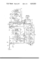
- FIG. 1 is a schematic diagram illustrating one portion of the system in accordance with the present invention.
- FIG. 2 is a schematic diagram of a second portion of the system of the invention. For ease of understanding, FIGS. 1 and 2 should be viewed together.
- a multiple hearth furnace 10 of conventional construction includes a refractory housing 11 of upright cylindrical configuration with a top closure member 11a. Within the housing are fixed a selected number of superimposed horizontal hearths 12, 14, 16 and 18 which are spaced apart relative to one another and to the top closure member 11a to define intervening hearth spaces 12a, 14a, 16a and 18a, respectively.
- the hearth spaces are in communication, one with another, via openings 13, 15 and 17 formed through the respective hearths 14, 16 and 18 at alternate central and peripheral locations.
- a vertical shaft 22 extends centrally through the superposed hearths and is coupled to a drive means 23 for rotation.
- the shaft 22 carries radially-extending rabble arms 24a, 24b, etc., positioned to rake material progressively across the hearths to the associated central or peripheral openings.
- a selectively closable feed hopper 30 is in communication with the upper hearth space 18a via an opening formed in the top closure member 11a. Also in communication with the upper hearth space 18a is an exhaust stack 32 mounted in a second opening formed through the closure member 11a. At the base of the furnace, a selectively closable discharge chute 28 is mounted in an opening formed through bottom hearth 12.
- Conventional burners 34 are mounted through the wall of the refractory housing 11 in communication with particular ones of the hearth spaces.
- Hearth spaces containing burners 34 are hereinafter said to be fired; in the illustrated embodiment, only the two middle hearth spaces 14a and 16a are fired.
- several burners are mounted in each of the fired hearth spaces, the exact number being a matter of design choice.
- Fuel such as natural gas
- a main distributor pipe 47 from which branch pipes 47a lead to the individual fired hearths.
- branch pipes 47a lead to the individual fired hearths.
- a shut-off valve 47b actuated by a solenoid 47c to govern the supply of fuel to the associated hearth space.
- a shut-off valve 47b is open if its associated solenoid 47c is energized and is closed if its associated solenoid is de-energized.
- lines 47e lead to the individual burners in the associated hearth spaces or, alternatively, a bustle-pipe type arrangement to supply several burners in the same hearth space can be utilized.
- a modulating valve 47d say of the globe type, which controls the amount of fuel flowing into the burner.
- the modulating valves 47d are controlled by pneumatic signals which are carried by lines 47f and which are responsive to the quantity of air supplied to the burner.
- the pneumatic signals control the burners so that the fuel-air ratio is maintained constant at some value regardless of air flow.
- Such burners are conventional and generally widely known in this art.
- a conventional mechanical control can be utilized which also maintains the fuel-air ratio constant at the burners.
- a blower 44 is connected to a main distributor conduit 45 from which branch conduits 45a lead to the individual burners or to a bustle pipe which serves a number of burners in the same hearth space.
- a variable-position modulating damper 45b which automatically controls the air flow therethrough according to the amplitude of control signals carried by lines 45c from a temperature monitoring unit 50 which, in turn, is coupled to a temperature probe 52 mounted in the associated hearth space.
- a temperature monitoring unit 50 is associated with each fired hearth space but, for purposes of clarity, only the unit 50 associated with hearth space 14a is shown in FIG. 1.
- Each temperature monitoring unit 50 functions to develop a control signal whose amplitude varies monotonically with the sensed temperature over a broad range.
- the control signals from the illustrated unit 50 are assumed to be pneumatic in the following description, but a temperature monitoring unit with electrical output signals could be utilized equivalently.
- the control signals are applied to the modulating damper 45b in the manner such that the damper progressively closes with increasing temperatures and progressively opens with decreasing temperatures.
- Such temperature monitoring units and modulating dampers are conventional and widely known in this art. Because of the action of the damper 45b, the quantity of air which flows through a branch line 45a is generally inversely related to the temperature sensed in the hearth space 14a. In other words, the air supply to the hearth space 14a is decreased with increasing temperatures and is increased with decreasing temperatures. This is called a reverse action control and is basically the same in result as the so-called inverse mode of operation which will be described later herein.
- the afterburner 60 Connected in communication with the furnace exhaust stack 32 is an afterburner 60.
- the afterburner includes a combustion chamber 62 and a gas outlet 66. Through the wall of the afterburner are mounted conventional burners 34a.
- the afterburner control system will be described further hereinafter.
- the multiple hearth furnace 10 is conventional. Were that furnace operated in a conventional manner, partially dewatered sewage sludge would be introduced through the feed hopper 30 and then would be dried as it was rabbled across the upper hearth 18 to discharge onto the next lower hearth 16 via the central opening 17. As the sludge was followingly rabbled across the fired hearths 16 and 14, the organics therein would be completely incinerated. Following that, the ashes and noncombustibles would be rabbled onto the lower hearth 12 for cooling and then would be discharged through the chute 28. Incineration in the fired hearths would be effectuated and sustained by supplying fuel and air through the burners 34.
- the amount of air supplied would be stoichiometrically excessive in order to assure complete destruction of the organics within the furnace and that would be accomplished by adjusting the fuel-air mixture to be relatively lean.
- the temperature control in the fired hearth spaces would be achieved by varying the air supply to the associated burners by means of the air modulating valves 47b, even at high temperatures. As the air supply was varied, the fuel supply would also be varied in direct proportion thereto by the fuel modulating valves 47d.
- the air and fuel supply would be decreased with increasing temperatures and would be increased with decreasing temperatures.
- the combustion gases and vapors would pass from the middle hearth spaces 14a and 16a into the upper hearth space 18a where they would contact the sludge feed and, because of that contact, would become slightly cooler and malodorous.
- the combustion gases would drive moisture from the sludge in the upper hearths and would partially dry the sludge.
- the combustion gases would be discharged from the upper hearth space 18a through the stack 32 and into the afterburner 60.
- the gases would be reheated in the afterburner chamber 62 by the introduction of auxiliary fuel and air through burners 34a.
- the control of fuel and air to the afterburner to effectuate such reheating would be accomplished in essentially the same manner as in the furnace 10, which is to say by the aforementioned reverse action control.
- an oxygen sensor 54 is mounted at a selected location in stack 32.
- the sensor 54 is coupled to a conventional oxygen monitoring unit 56 which measures the oxygen level of the gases in the stack and indicates when the oxygen level falls below a certain predetermined level.
- each of the fired hearth spaces in the furnace 10 a selected number of air nozzles 58 are mounted at spaced apart intervals on the wall of the refractory housing 11.
- a branch conduit 59 extends from the main distributor conduit 45 to each fired hearth space to supply air to the air nozzles associated with the hearth space.
- FIG. 1 shows only one air nozzle per fired hearth space and shows only the branch conduit that is associated with that air nozzle.
- a variable-position modulating damper 59a which controls the air flow to the air nozzles.
- Each modulating damper 59a is connected to receive the pneumatic output signals from the temperature monitoring unit 50 associated with the same hearth space.
- the dampers 59a are generally the same as the aforedescribed dampers 45b and are connected to operate in the same manner; that is, the dampers 59a will progressively close and restrict the air flow as the associated temperature monitoring unit senses increasing temperatures and the dampers will progressively open to allow more air flow as the monitoring unit senses decreasing temperatures.
- the temperature monitoring unit control signals are carried to the modulating dampers 59a by lines 59b.
- the control signals to a modulating damper 59a are identical to the ones applied to the damper 45b associated with the hearth space.
- Interposed in each control line 59b is a three-way valve 70 which can assume two alternative positions as determined by a solenoid actuator 72 connected thereto.
- the modulating damper 59a In the first position, the modulating damper 59a is connected, via the three-way valve 70, to a constant pressure source 74 which holds the modulating damper in a predetermined fixed position (e.g., 25% open).
- a predetermined fixed position e.g. 25% open
- a three-way valve 70 is in the first position when its associated solenoid actuator is energized and is in the second position whenever the associated solenoid actuator is de-energized.
- the furnace control network 99 for fired hearth space 14a includes four branches 100, 102, 104 and 106 connected in parallel across main conductors 110 and 112. The main conductors are in turn coupled to a power source, not shown, that establishes a constant voltage potential between the conductors.
- a power source not shown
- one such control network is provided for each of the fired hearth spaces in the furnace 10 but, for purposes of clarity and explanation, only the control network 99 for the fired hearth space 14a is illustrated here.
- Branch 100 in network 99 includes the series combination of a normally open contact C1, a normally closed contact C2, a normally closed temperature-controlled contact C3 and a relay R1.
- Another normally open contact C4 is connected in parallel across the series combination of contacts C1 and C2.
- the contact C3 is controlled by the aforementioned temperature monitoring unit 50; it opens only when temperatures in excess of some predetermined high temperature (e.g., 1700° F) are sensed within the associated hearth space 14a by the temperature probe 52.
- the relay R1 illustrated as a conventional induction device, will be energized only when current flows through branch 100. In the illustrated embodiment, that will occur only when the three contacts C1, C2 and C3 are all closed, or when contacts C4 and C3 are both closed.
- the relay R1 is connected to actuate the normally open contact C1, as indicated by the dashed line, and controls the position of that contact. In other words, the contact C1 will be open whenever the relay R1 is de-energized and will be closed whenever the relay is energized.
- the position of the normally closed contact C2 is controlled by the aforementioned oxygen monitoring unit 56 as indicated by the dashed line 202. Specifically, the contact C2 is commanded to open whenever the oxygen level monitored in the stack falls below a certain predetermined value. FIG. 2, therefore, shows contact C2 in the position that is has when the monitored oxygen level is above the limit value.
- Branch 102 includes a temperature-controlled contact C6 in series with a relay R2. As indicated by the dashed line 203, the contact C6 is also controlled by the temperature monitoring unit 50 and opens only when the monitoring unit senses temperatures in excess of some predetermined low temperature (e.g., 1400° F) within the associated hearth space 14a.
- FIG. 2 shows the contact C6 in the position that it has when temperatures exceed the low temperature limit in hearth space 14a.
- relay R2 is coupled to control the position of the normally open contact C4 in branch 100 and that contact C4 will be closed whenever relay R2 is energized (i.e., when temperatures in hearth space 14a are below the low temperature limit).
- Branch 104 includes a normally open contact C7 in series with a relay R3.
- the contact C7 is controlled by the aforementioned relay R1 in branch 100 and will be closed whenever that relay is energized.
- the relay R3 is connected to control the energization of the solenoid actuator 72 which is coupled to the three-way valve 70.
- energization of the relay R3 energizes the solenoid actuator 72 and that, in turn, places the modulating damper 59a in communication with the constant pressure source 74, the result being that the modulating damper 59a is held in the aforementioned fixed-open position by the constant pressure source.
- the solenoid actuator 72 is de-energized when the relay R3 is de-energized and, in that case, the modulating damper is under the command of the temperature monitoring unit 50.
- Branch 106 includes a series combination of a normally open contact C8, a burner safety control 107, and a relay R4.
- the contact C8 is controlled by the relay R1 in branch 100 and will be closed only when that relay is energized.
- the burner safety control 107 is a conventional component which, for present purposes, can be considered to comprise a switch which is open whenever some predetermined unsafe condition exists in the furnace; the unsafe condition could, for example, be that the fan 44 is not operating or that a low fuel pressure condition exists.
- the relay R4 is connected to control the solenoid 47c which is coupled to the fuel shut-off valve 47b.
- control network 99 for hearth space 14a The operation of the control network 99 for hearth space 14a will now be described. Again, it should be understood that the other fired hearth spaces in the furnace are equipped with identical control systems, all of which will function in the same manner.
- both temperature-controlled contacts C3 and C6 will be closed by the action of temperature monitoring unit 50. With contact C6 closed, current will flow through branch 102 and will energize relay R2. Energization of the relay R2 will cause contact C4 to close and, because of that, relay R1 will be energized by the flow of current through branch 100. Energization of the relay R1 will cause contacts C1, C7 and C8 to close.
- Closure of the contact C7 energizes relay R3 and that, in turn, energizes the solenoid actuator 72 to position the three-way valve 70 such that control signals from the temperature monitoring unit 50 are blocked from reaching the variable-position modulating damper 59a which governs the air supply to the air nozzles 58 in hearth space 14a.
- the modulating damper 59a is held in the aforementioned fixed-open position so long as the relay R3 is energized.
- Closure of contact C8 by the relay R1 will, in turn, energize relay R4 if the burner safety system 107 does not detect an unsafe furnace condition.
- Energization of relay R4 causes the energization of solenoid 47c and that opens the shut-off valve 47b so that fuel is supplied to the burners 34 in the hearth space 14a.
- air is supplied to burners 34 via the branch conduit 45a and the flow therethrough is automatically controlled by the modulating valve 45b under command of the temperature monitoring unit 50.
- Such commands cause the fuel and air supply to be choked or restricted when the temperatures rise within the hearth space 14a, and cause the fuel and air supply to be increased when the temperatures fall within the hearth space 14a.
- the low temperature contact C6 Whenever the temperature in the hearth space 14a exceeds the low temperature limit (e.g., 1400° F), the low temperature contact C6 will open under command of the temperature monitoring unit 50. Opening of the contact C6 will de-energize relay R2 which, in turn, will cause contact C4 to open. However, unless the oxygen level monitored in the stack 32 is below a particular predetermined level as sensed by the oxygen monitoring unit 56, the opening of contact C4 will have no effect upon the fuel or air supply to the hearth space 14a. (That is so because relay R1 will remain energized by current flowing through the series of closed contacts C1, C2 and C3.)
- the low temperature limit e.g. 1400° F
- the solenoid actuator 72 will be de-energized and will cause the three-way valve 70 to shift so that the modulating damper 59a is under the command of the temperature monitoring unit 50 and the air supply to the nozzles 58 in the hearth space 14a is modulated in parallel with the air supply to the burners 34 in the hearth space.
- the relay R1 when the relay R1 is de-energized, it opens the contact C1 which precedes it in the branch 100. Therefore, even if contact C3 is subsequently closed due to a decrease in temperature, current cannot flow through branch 100 to energize the relay R1 unless the contact C4 is closed. This so-called temperature dead band feature will be discussed further hereinafter.
- the action described for the high temperature situation will also occur if the monitored oxygen level drops below the predetermined limit when the temperature in hearth space 14a is between the high and low temperature limits at which contacts C6 and C3 are actuated. That is, the relay R1 will also be de-energized if contact C2 is opened by the oxygen monitoring unit 50 at the same time that the low-temperature contact C6 is open and high-temperature contact C3 is closed. This is called the oxygen-starvation situation. In the oxygen starvation situation, no fuel will be supplied to the burners 34 and the air supply will be modulated in the aforementioned reverse action mode.
- the furnace control system prevents fuel from being supplied to the monitored hearth space in either the high temperature situation or in the oxygen starvation situation when the temperature in the monitored hearth space is above a predetermined low level temperature (e.g., 1400° F).
- a predetermined low level temperature e.g. 1400° F.
- Re-energization of relay R1 also closes the contact C7 which, in turn, re-energizes the relay R3 which causes the solenoid actuator 72 to be energized and, following, causes the modulating damper 59 to be placed under control of the constant pressure source 74.
- the relay R1 is not energized merely by closing high temperature contact C3; in addition, contact C4 must be closed and that, in turn, requires the activation of the low temperature relay R2. This is the previously mentioned dead band feature and it prevents on/off fluttering of the control systems.
- both the air nozzles and burners in the fired hearths are adjusted such that the amount of air introduced to the furnace at any temperature is less than that which is required stoichiometrically for the complete combustion of organics within the monitored hearth spaces at a preselected feed rate.
- the furnace is operated to pyrolyze, not to completely combust, the feed materials.
- burnable organics in the volatilized gases is a potential heat source which is utilized in the afterburner in a manner that will now be described.
- a temperature sensor 82 which is coupled via line 83 to a temperature monitoring unit 84 generally similar to the aforementioned units 50 employed in the furnace control systems.
- a reversing means 85 is interposed in the output line of the temperature monitoring unit 84.
- This reversing means is a conventional and generally widely known device capable of switching the output signals of the temperature monitoring unit 84 between a "direct” mode, wherein the output signals from the temperature monitoring unit 84 monotonically increase in magnitude with increasing temperatures and an "inverse" mode wherein the output signals from the monitoring unit monotonically decrease in magnitude with increasing temperatures.
- the dampers will progressively open to admit more air with increasing temperatures and will progressively close with decreasing temperatures.
- the afterburner dampers which receive direct mode control signals will operate the opposite of dampers in the furnace control system described previously.
- the same result can be achieved by providing conventional signal-switching devices other than those described previously.
- the important point here is that, in the so-called direct mode, the air supply to the afterburner is increased with increasing temperatures and is decreased with decreasing temperatures.
- the afterburner control system operates in the inverse mode unless the reversing device 85 is energized, and that when the reversing device is energized the control system operates in the direct mode.
- an oxygen sensor 54 which is coupled, via line 86, to an oxygen monitoring unit 87 which may be identical to the aforementioned unit 56 employed in the furnace control system.
- the afterburner temperature monitoring unit 84, the afterburner oxygen monitoring unit 87, and the reversing means 85 are coupled to an afterburner control network 119 (FIG. 2) that will be described hereinafter.
- a selected number of burners 34a are also mounted within the afterburner 60. (For purposes of clarity, only one such burner is illustrated.)
- the aforementioned main fuel distributor pipe 47 is connected to the burners 34a via a branch pipe 88 wherein is interposed a shut-off valve 88a controlled by a solenoid 88b to govern the supply of fuel through the branch pipe 88.
- shut-off valve 88a is open so long as its associated solenoid 88b is energized and is closed if the solenoid is de-energized.
- pneumatically-controlled modulating valves 82c like the ones connected to the burners with the fired hearths in the furnace and they act in response to the quantity of air supplied to the burners to keep the fuel-air ratio constant.
- a branch conduit 89 which leads from the aforementioned main air distributor conduit 45.
- a variable-position modulating damper 89a like the dampers 45b associated with the fired hearths in the furnace, which automatically controls the air flow therethrough according to the amplitude of control signals carried by lines 89b from the temperature monitoring unit 84.
- a branch conduit 90 extends from the main air distributor conduit 45.
- a pneumatically actuated variable-position modulating damper 90a also like the dampers 59a associated with the fired hearths in the furnace, which controls the air flow to the air nozzles.
- the modulating damper 90a is controlled by pneumatic signals from the afterburner temperature monitoring unit 84, which signals are carried to the modulating damper by line 90b and are the same as the ones applied to the damper 89a which controls the air supply to the burners 34a in the afterburner.
- a three-way valve 91 Interposed in the control line 90b is a three-way valve 91 which can assume two alternative positions as determined by a solenoid actuator 92 connected thereto.
- the modulating damper 90a In the first position, the modulating damper 90a is connected via the three-way valve 91 to a constant pressure source 93 which holds the modulating damper in a predetermined fixed-open position (e.g., 25% open).
- a predetermined fixed-open position e.g. 25% open
- the temperature monitoring unit 84 In the second position, there is direct communication between the temperature monitoring unit 84 and the modulating damper 90a through the three-way valve 91.
- the three-way valve 91 In the following description, it will be assumed that the three-way valve 91 is in the first position whenever its solenoid actuator 92 is energized and is in the second position whenever its solenoid is de-energized. Energization of the solenoid actuator 92 is controlled by an afterburner control network which will now be described
- control network 119 for the afterburner includes five branches 120, 122, 124, 126 and 128 connected in parallel across the aforementioned main conductors 110 and 112.
- Branch 120 includes the series combination of a normally open contact C9, two normally closed contacts C10 and C11, and a relay R5.
- a normally open contact C12 is connected in parallel across the series combination of contacts C9 and C10.
- the relay R5 will be energized only when the three contacts C9, C10 and C11 are all closed, or when contacts C12 and C11 are both closed.
- the relay R5 is connected to actuate the contact C9 preceding it in the branch 120; that contact will be closed whenever the relay R5 is energized.
- the contact C11 is controlled by the aforementioned temperature monitoring unit 84 and opens only when temperatures in excess of some predetermined high temperature (e.g., 1450° F) are sensed within the afterburner 60.
- the position of the normally closed contact C10 is controlled by the oxygen monitoring unit 87 as indicated by the dashed line 212. The oxygen monitoring unit commands the contact to open whenever the oxygen level within the afterburner falls below a certain preselected value.
- Branch 122 includes a normally closed contact C14 in series with a relay R6. As indicated by the dashed line 213, the contact C14 is also controlled by temperature monitoring unit 84 and opens only when the monitoring unit senses temperatures in excess of some predetermined low temperature (e.g., 1200° F) within the afterburner. FIG. 2 shows the contact C14 in the position that it has when afterburner temperatures exceed the low temperature limit. It should be noted that relay R6 is coupled to control the position of the normally open contact C12 in branch 120 and that contact C12 will be closed whenever relay R6 is energized.
- some predetermined low temperature e.g. 1200° F
- Branch 124 includes the series combination of a normally closed contact C15, a normally open temperature-controlled contact C16, and a relay R7.
- a normally closed contact C17 is connected in parallel with the contact C16.
- the normally closed contact C15 is controlled by the relay R5 in the branch 120 and will be opened whenever that relay is energized.
- the contact C16 is controlled by the temperature monitoring unit 84 and closes only when the monitoring unit senses temperatures in excess of some predetermined intermediate temperature (e.g., 1350° F) within the afterburner. (Note that FIG.
- the contact C17 is controlled by the oxygen monitoring unit 87, which unit commands the contact C17 to open simultaneously with the contact C10 in the branch 120 whenever the oxygen level within the afterburner falls below a certain preselected value.
- the relay R7 is coupled to energize the aforementioned reversing means 85, which means is energized whenever relay R7 is energized.
- the relay R7 is hereinafter called the reversing relay.
- the temperature monitoring unit 84 is placed in the direct mode of operation if, and only if, the reversing relay R7 is energized.
- the important result of the temperature monitoring unit 84 operating in the direct mode is that the air supply to the afterburner is increased with increasing temperatures and is decreased with decreasing temperatures.
- Branch 126 includes a normally open contact C18 in series with a relay R8.
- the contact C18 is controlled by the aforementioned relay R5 in branch 120 and will be closed whenever that relay is energized.
- the relay R8 is connected to control the energization of the solenoid actuator 92 coupled to the three-way valve 91.
- energization of the relay R8 energizes the solenoid actuator 92 and that, in turn, places the modulating damper 90a in communication with the constant pressure source 93, the result being that the modulating damper 90a is held in the aforementioned fixed-open position by the constant pressure source.
- the solenoid actuator 92 is de-energized when the relay R8 is de-energized and, in that case, the modulating damper 90a is under the command of the temperature monitoring unit 84.
- the branch 128 includes the series combination of a normally open contact C19, a burner safety control 129, and a relay R9.
- the contact C19 is controlled by the relay R5 in branch 120 and will be closed only when that relay is energized.
- the relay R9 is connected to control the energization of the solenoid 88b which is coupled to the afterburner fuel shut-off valve 88a.
- energization of the relay R9 energizes the solenoid 88b and that, in turn, opens the fuel shut-off valve 88a.
- the solenoid 88b is also de-energized and the shut-off valve 88a blocks the fuel supply line 88 to the afterburner.
- the control network 119 for the afterburner will now be described.
- the afterburner control system is rather similar to the control systems associated with the fired hearth spaces in the furnace 10, there are several important differences.
- One difference is that the afterburner control system includes the reversing means 85 and its control branch 124 in the network 119.
- the burners and air nozzles in the afterburner are adjusted to maintain an abundance of air in excess of that which is required for stoichiometric combustion.
- the burners and air nozzles are adjusted such that the amount of air introduced to the furnace is less than that which is required for stoichiometric combustion.
- the temperature-controlled contacts C11 and C14 will be closed and C16 will be open by the action of the temperature monitoring unit 84. With contact C14 closed, current will flow through branch 122 and will energize relay R6. Energization of the relay R6 will cause contact C12 to close and, because of that, relay R5 will be energized by the flow of current through branch 120 (i.e., through contacts C12 and C11 in series). Energization of the relay R5 will cause contacts C9, C18 and C19 to close and will cause the contact C15 to open.
- the low temperature limit i.e. 1200° F in the illustrated embodiment
- Closure of the contact C18 energizes the relay R8 and that, in turn, energizes the solenoid actuator 92 to position the three-way valve 91 such that the constant pressure source 93 holds the modulating damper 90a in the partially fixed-open position.
- Closure of the contact C19 by the relay R5 will, so long as the burner safety system does not detect an unsafe afterburner condition, energize the relay R9. Energization of that relay will cause the solenoid 88b to become energized and it, in turn, opens the shut-off valve 88a so that fuel is supplied to the burners 34a in the afterburner.
- the temperature-controlled contact C14 will open and the relay R6 will be de-energized. However, that will have no effect upon the fuel and air supply to the afterburner. In other words, de-energization of the relay R6 will not open circuit branch 120 under the stated conditions because the contacts C9, C10 and C11 will be closed and will provide an alternate current path through the branch.
- the temperature-controlled contact C16 will close. That still will have no effect on the reversing relay R7, however, because it will remain de-energized due to the open condition of contact C15.
- the temperature-controlled contact C11 will open and that will de-energize the relay R5.
- De-energization of the relay R5 causes contacts C18 and C19 to open and they, in turn, de-energize relays R8 and R9, respectively.
- the solenoid 88b will be de-energized and that will cause the shut-off valve 88a to block the fuel supply line 88. That is, there will be a "no-fuel" condition.
- the solenoid actuator 92 will be de-energized and will cause the three-way valve 91 to shift so that the modulating damper 90a is under the command of the temperature monitoring unit 84 and, accordingly, the air supply to the nozzles 58a will be modulated in parallel with the air supply to the burners 34a in the afterburner.
- Another effect of the de-energization of the relay R5 in the high temperature situation is to close the contact C15 in branch 124. With contact C15 closed, current will flow through branch 124 via contacts C15 and C17 and will energize the relay R7. In turn, relay R7 energizes the reversing means 85 so that the temperature monitoring unit 84 operates in the aforementioned direct mode. In that mode of operation, the air supply to the afterburner is increased with increasing temperatures and is decreased with decreasing temperatures. This is called the "air quenching" mode of operation and, as mentioned previously, it will be accompanied by a no-fuel condition.
- oxygen monitoring unit 87 will open the contacts C10 and C17, but neither contact will affect the operation of the system at this time. That is, the relay R5 will have been previously de-energized by the opening of the temperature controlled contact C11. Also, the reversing relay R7 will remain energized by the flow of current through branch 124 via the closed contacts C15 and C16.
- the system will react and the air quenching mode will cease. In that case, the contacts C16 and C17 will both be open and, hence, there will be no current flow through the branch 124. As a result, the reversing relay R7 will be de-energized and the system will operate to the inverse mode and without fuel.
- the quenching mode will continue. That is so because the reversing relay R7 will remain energized by the flow of current through branch 124 via the contacts C15 and C17.
- the quenching mode will cease regardless of the oxygen level in the afterburner. That is so because the relay R5 is always energized at low temperatures and it controls the contact C15 to open circuit the branch 124. Without current flow through branch 124, the reversing relay R7 and the reversing means 85 are de-energized and the system operates in the inverse mode. It should be apparent that the inverse mode is desirable under these conditions because fuel is being added to the afterburner and there is no quenching effect to inhibit the temperatures from rising to a desired level.
- the quenching mode of operation will not be initiated until temperatures in the afterburner rise above the high temperature limit but, once initiated, the quenching mode will not cease until temperatures fall below the intermediate temperature limit.
- there is a dead band feature in the afterburner control system which prevents fluttering of the system due to small temperature changes about the high temperature limit.
- the afterburner need not be separate from the furnace.
- the upper hearth space 18a of the furnace may be operated as an afterburner.
- the upper hearth space would be provided with burners, air nozzles, and so forth as in the aforedescribed afterburner. If that is done, the probe for oxygen monitoring unit 56 for the fired hearths would be located within the furnace proper to monitor the oxygen level of the gases prior to their entry into the upper hearth space 18a.
- sewage sludge containing organic wastes is intended to encompass analogous sludges which, for example, are derived from industrial processes and which contain organic materials.
- partially dewatered refers to sludges which are typically from about fifteen to about fifty percent solids by weight and, usually, less than forty percent solids by weight.
- incinerating devices other than multiple hearth furnaces.
- conventional fluidized bed furnaces or conventional rotary pyrolyzers can be equipped with afterburners and then operated as described hereinbefore. That is to say, such incinerating devices can be operated with a deficiency of air over their operating ranges while their afterburners are operated with excess air supplied in quantities to control afterburner temperatures by quenching.
Landscapes
- Engineering & Computer Science (AREA)
- Mechanical Engineering (AREA)
- General Engineering & Computer Science (AREA)
- Incineration Of Waste (AREA)
- Gasification And Melting Of Waste (AREA)
Priority Applications (18)
| Application Number | Priority Date | Filing Date | Title |
|---|---|---|---|
| US05/645,063 US4013023A (en) | 1975-12-29 | 1975-12-29 | Incineration method and system |
| NZ182653A NZ182653A (en) | 1975-12-29 | 1976-11-17 | Sludge incineration in multiple hearth furnace |
| ZA767020A ZA767020B (en) | 1975-12-29 | 1976-11-23 | Incineration method and system |
| AU19948/76A AU507015B2 (en) | 1975-12-29 | 1976-11-24 | Method and system forthe incineration of partially dewatered sewage sludge |
| IT29906/76A IT1064521B (it) | 1975-12-29 | 1976-11-29 | Metodo ed impianto di incenerimento |
| NL7613541A NL7613541A (nl) | 1975-12-29 | 1976-12-06 | Werkwijze en inrichting voor het verassen van tendele ontwaterd rioolslib. |
| FR7637206A FR2337308A1 (fr) | 1975-12-29 | 1976-12-10 | Procede et systeme d'incineration de boues partiellement deshydratees contenant des dechets organiques dans un four a soles multiples |
| DE19762656379 DE2656379A1 (de) | 1975-12-29 | 1976-12-13 | Verfahren und vorrichtung zum verbrennen von teilweise entwaessertem abwasserschlamm |
| FI763577A FI763577A7 (show.php) | 1975-12-29 | 1976-12-13 | |
| CA268,309A CA1038235A (en) | 1975-12-29 | 1976-12-20 | Incineration method and system |
| JP15410876A JPS5282874A (en) | 1975-12-29 | 1976-12-21 | Incineration method and apparatus |
| GB53472/76A GB1573118A (en) | 1975-12-29 | 1976-12-22 | Incineration method and system |
| ES454563A ES454563A1 (es) | 1975-12-29 | 1976-12-23 | Metodo y su correspondiente aparato para incinerar lodo de alcantarilla parcialmente deshidratado. |
| BR7608741A BR7608741A (pt) | 1975-12-29 | 1976-12-28 | Aperfeicoamento em processo de incinerar lama de esgoto parcialmente desaguada contendo refugos organicos |
| SE7614611A SE7614611L (sv) | 1975-12-29 | 1976-12-28 | Sett och anordning ffor forbrenning |
| BE173662A BE849890A (fr) | 1975-12-29 | 1976-12-28 | Procede et systeme d'incineration de boues partiellement deshydratees contenant des dechets organiques dans un fouer a soles multiples |
| DK586876A DK586876A (da) | 1975-12-29 | 1976-12-29 | Fremgangsmade og apparat til brending af delvis afvandet spildevandsslam |
| US06/066,701 USRE31046E (en) | 1975-12-29 | 1979-08-15 | Incineration method and system |
Applications Claiming Priority (1)
| Application Number | Priority Date | Filing Date | Title |
|---|---|---|---|
| US05/645,063 US4013023A (en) | 1975-12-29 | 1975-12-29 | Incineration method and system |
Related Child Applications (1)
| Application Number | Title | Priority Date | Filing Date |
|---|---|---|---|
| US06/066,701 Reissue USRE31046E (en) | 1975-12-29 | 1979-08-15 | Incineration method and system |
Publications (1)
| Publication Number | Publication Date |
|---|---|
| US4013023A true US4013023A (en) | 1977-03-22 |
Family
ID=24587508
Family Applications (1)
| Application Number | Title | Priority Date | Filing Date |
|---|---|---|---|
| US05/645,063 Expired - Lifetime US4013023A (en) | 1975-12-29 | 1975-12-29 | Incineration method and system |
Country Status (17)
| Country | Link |
|---|---|
| US (1) | US4013023A (show.php) |
| JP (1) | JPS5282874A (show.php) |
| AU (1) | AU507015B2 (show.php) |
| BE (1) | BE849890A (show.php) |
| BR (1) | BR7608741A (show.php) |
| CA (1) | CA1038235A (show.php) |
| DE (1) | DE2656379A1 (show.php) |
| DK (1) | DK586876A (show.php) |
| ES (1) | ES454563A1 (show.php) |
| FI (1) | FI763577A7 (show.php) |
| FR (1) | FR2337308A1 (show.php) |
| GB (1) | GB1573118A (show.php) |
| IT (1) | IT1064521B (show.php) |
| NL (1) | NL7613541A (show.php) |
| NZ (1) | NZ182653A (show.php) |
| SE (1) | SE7614611L (show.php) |
| ZA (1) | ZA767020B (show.php) |
Cited By (37)
| Publication number | Priority date | Publication date | Assignee | Title |
|---|---|---|---|---|
| US4144014A (en) * | 1977-01-04 | 1979-03-13 | Ciba-Geigy Corporation | Process for the thermal combustion of waste gases and thermal after-burning plant for carrying out said process |
| US4145979A (en) * | 1978-01-23 | 1979-03-27 | Envirotech Corporation | Afterburner assembly |
| US4166421A (en) * | 1976-08-20 | 1979-09-04 | Heenan Environmental Systems Ltd. | Cyclonic furnace |
| US4182246A (en) * | 1978-01-16 | 1980-01-08 | Envirotech Corporation | Incineration method and system |
| US4241672A (en) * | 1978-12-04 | 1980-12-30 | The United States Of America As Represented By The United States Department Of Energy | Method of regulating the amount of underfire air for combustion of wood fuels in spreader-stroke boilers |
| US4270467A (en) * | 1980-01-14 | 1981-06-02 | Enertherm, Inc. | Low mass flow waste fuel incinerator |
| US4279208A (en) * | 1978-12-04 | 1981-07-21 | L'air Liquide, Societe Anonyme Pour L'etude Et L'exploitation Des Procedes Georges Claude | Method and apparatus for heat treatment of industrial wastes |
| US4300460A (en) * | 1978-03-10 | 1981-11-17 | Enterprises International Inc. | Method for generating heat from waste fuel |
| US4316420A (en) * | 1978-11-06 | 1982-02-23 | Combustion Engineering, Inc. | Furnace heat absorption control |
| US4332206A (en) * | 1980-05-09 | 1982-06-01 | The Boeing Company | Afterburner for combustion of starved-air combustor fuel gas containing suspended solid fuel and fly ash |
| US4334484A (en) * | 1980-01-18 | 1982-06-15 | University Of Kentucky Research Foundation | Biomass gasifier combustor |
| US4378208A (en) * | 1980-01-18 | 1983-03-29 | University Of Kentucky Research Foundation | Biomass gasifier combustor |
| US4391208A (en) * | 1980-09-29 | 1983-07-05 | Sterling Drug, Inc. | Method for controlling temperatures in the afterburner and combustion hearths of a multiple hearth furnace |
| EP0020735B1 (en) * | 1978-12-27 | 1983-11-16 | Hooker Chemicals & Plastics Corp. | Flash drying sludge derived fuel process |
| US4434725A (en) | 1982-02-16 | 1984-03-06 | Samuel Foresto | Mass burning self-cleaning incinerator |
| US4453474A (en) * | 1980-09-29 | 1984-06-12 | Sterling Drug, Inc. | Method for controlling temperatures in the afterburner and combustion hearths of a multiple hearth furnace |
| US4459923A (en) * | 1983-02-18 | 1984-07-17 | Sterling Drug, Inc. | Method and apparatus for efficiently controlling the incineration of combustible materials in a multiple hearth furnace system |
| US4474121A (en) * | 1981-12-21 | 1984-10-02 | Sterling Drug Inc. | Furnace control method |
| US4481890A (en) * | 1980-09-29 | 1984-11-13 | Sterling Drug Inc. | Method for controlling temperatures in the afterburner and combustion hearths of a multiple hearth furnace |
| US4517906A (en) * | 1983-08-30 | 1985-05-21 | Zimpro Inc. | Method and apparatus for controlling auxiliary fuel addition to a pyrolysis furnace |
| US4531462A (en) * | 1980-01-18 | 1985-07-30 | University Of Kentucky Research Foundation | Biomass gasifier combustor |
| US4649834A (en) * | 1986-01-27 | 1987-03-17 | Armature Coil Equipment, Inc. | Temperature control system for pyrolysis furnace |
| US4742783A (en) * | 1987-08-06 | 1988-05-10 | Phillips Petroleum Company | Incinerator combustion air control |
| US4852504A (en) * | 1988-06-20 | 1989-08-01 | First Aroostook Corporation | Waste fuel incineration system |
| US4861262A (en) * | 1984-08-17 | 1989-08-29 | American Combustion, Inc. | Method and apparatus for waste disposal |
| US4870910A (en) * | 1989-01-25 | 1989-10-03 | John Zink Company | Waste incineration method and apparatus |
| US4951579A (en) * | 1987-11-18 | 1990-08-28 | Radian Corporation | Low NOX combustion process |
| US4982672A (en) * | 1987-11-18 | 1991-01-08 | Radian Corporation | Low NOX incineration process |
| USRE34298E (en) * | 1984-08-17 | 1993-06-29 | American Combustion, Inc. | Method for waste disposal |
| US5569030A (en) * | 1992-07-14 | 1996-10-29 | Cadence Environmental Energy, Inc. | Method for improved manufacture of cement in long kilns |
| EP0921353A2 (en) | 1997-12-02 | 1999-06-09 | Eco Waste Solutions Inc. | Controlled thermal oxidation process for organic waste |
| US6200128B1 (en) * | 1997-06-09 | 2001-03-13 | Praxair Technology, Inc. | Method and apparatus for recovering sensible heat from a hot exhaust gas |
| US6546883B1 (en) * | 2000-07-14 | 2003-04-15 | Rgf, Inc. | Thermo-oxidizer evaporator |
| US20040156959A1 (en) * | 2003-02-07 | 2004-08-12 | Fink Ronald G | Food surface sanitation tunnel |
| US20060107595A1 (en) * | 2004-11-23 | 2006-05-25 | Kenneth Davison | Side feed/centre ash dump system |
| EP2068081A4 (en) * | 2006-09-26 | 2011-05-11 | Kobelco Eco Solutions Co Ltd | OPERATING METHOD AND OPERATING CONTROL DEVICE FOR GASIFYING OVEN |
| RU2663433C1 (ru) * | 2017-07-03 | 2018-08-06 | Общество с ограниченной ответственностью "Современные пиролизные технологии" (ООО "СПТ") | Способ переработки твердого топлива с получением горючего газа и реактор для его осуществления |
Families Citing this family (6)
| Publication number | Priority date | Publication date | Assignee | Title |
|---|---|---|---|---|
| US4507127A (en) * | 1981-12-21 | 1985-03-26 | Nippon Furnace Kogyo Co., Ltd. | System for recovering resources from sludge |
| NZ205994A (en) * | 1982-11-18 | 1985-07-31 | Warren Eng Pty | Sewage screenings disposal system-compressed screenings incinerated |
| DE3928748A1 (de) * | 1989-08-30 | 1991-03-07 | Bela Medvey | Verfahren und vorrichtung zum verbrennen von feuchtem verbrennungsgut |
| RU2164239C2 (ru) * | 1998-03-12 | 2001-03-20 | Юдкевич Юрий Давидович | Устройство для пиролиза бытовых отходов |
| ES2177358B1 (es) * | 1999-03-31 | 2003-11-01 | Aplicaciones Tecn Para Raciona | Horno incinerador de restos de exhumacion. |
| CA3194413A1 (en) * | 2020-10-01 | 2022-04-07 | Juan Carlos Josse | Volatilization and oxidation of organic waste |
Citations (4)
| Publication number | Priority date | Publication date | Assignee | Title |
|---|---|---|---|---|
| US2015051A (en) * | 1933-03-30 | 1935-09-17 | Nichols Eng & Res Corp | Drying and incinerating of sewage, garbage, etc. |
| US2063630A (en) * | 1933-04-07 | 1936-12-08 | Nichols Eng & Res Corp | Drying and incinerating of sewage, garbage, etc. |
| US2114566A (en) * | 1936-11-21 | 1938-04-19 | Underpinning & Foundation Comp | Incineration |
| US3958920A (en) * | 1975-06-03 | 1976-05-25 | Rust Engineering Company | System for controlling the operation of a multiple hearth furnace |
Family Cites Families (5)
| Publication number | Priority date | Publication date | Assignee | Title |
|---|---|---|---|---|
| JPS429429Y1 (show.php) * | 1964-07-22 | 1967-05-22 | ||
| JPS454000Y1 (show.php) * | 1969-06-19 | 1970-02-24 | ||
| CA953979A (en) * | 1970-07-13 | 1974-09-03 | Edward T. Bielski | Apparatus and method for pyrolyzing heat-decomposable non-gaseous materials |
| US3727564A (en) * | 1971-09-09 | 1973-04-17 | Air Preheater | Modulated fuel |
| US3855950A (en) * | 1973-10-10 | 1974-12-24 | Consumat Syst Inc | Automatic loading and ash removal system for incinerators |
-
1975
- 1975-12-29 US US05/645,063 patent/US4013023A/en not_active Expired - Lifetime
-
1976
- 1976-11-17 NZ NZ182653A patent/NZ182653A/xx unknown
- 1976-11-23 ZA ZA767020A patent/ZA767020B/xx unknown
- 1976-11-24 AU AU19948/76A patent/AU507015B2/en not_active Expired
- 1976-11-29 IT IT29906/76A patent/IT1064521B/it active
- 1976-12-06 NL NL7613541A patent/NL7613541A/xx not_active Application Discontinuation
- 1976-12-10 FR FR7637206A patent/FR2337308A1/fr not_active Withdrawn
- 1976-12-13 DE DE19762656379 patent/DE2656379A1/de not_active Withdrawn
- 1976-12-13 FI FI763577A patent/FI763577A7/fi not_active Application Discontinuation
- 1976-12-20 CA CA268,309A patent/CA1038235A/en not_active Expired
- 1976-12-21 JP JP15410876A patent/JPS5282874A/ja active Pending
- 1976-12-22 GB GB53472/76A patent/GB1573118A/en not_active Expired
- 1976-12-23 ES ES454563A patent/ES454563A1/es not_active Expired
- 1976-12-28 BE BE173662A patent/BE849890A/xx unknown
- 1976-12-28 SE SE7614611A patent/SE7614611L/xx unknown
- 1976-12-28 BR BR7608741A patent/BR7608741A/pt unknown
- 1976-12-29 DK DK586876A patent/DK586876A/da unknown
Patent Citations (4)
| Publication number | Priority date | Publication date | Assignee | Title |
|---|---|---|---|---|
| US2015051A (en) * | 1933-03-30 | 1935-09-17 | Nichols Eng & Res Corp | Drying and incinerating of sewage, garbage, etc. |
| US2063630A (en) * | 1933-04-07 | 1936-12-08 | Nichols Eng & Res Corp | Drying and incinerating of sewage, garbage, etc. |
| US2114566A (en) * | 1936-11-21 | 1938-04-19 | Underpinning & Foundation Comp | Incineration |
| US3958920A (en) * | 1975-06-03 | 1976-05-25 | Rust Engineering Company | System for controlling the operation of a multiple hearth furnace |
Cited By (42)
| Publication number | Priority date | Publication date | Assignee | Title |
|---|---|---|---|---|
| US4166421A (en) * | 1976-08-20 | 1979-09-04 | Heenan Environmental Systems Ltd. | Cyclonic furnace |
| US4144014A (en) * | 1977-01-04 | 1979-03-13 | Ciba-Geigy Corporation | Process for the thermal combustion of waste gases and thermal after-burning plant for carrying out said process |
| US4182246A (en) * | 1978-01-16 | 1980-01-08 | Envirotech Corporation | Incineration method and system |
| US4145979A (en) * | 1978-01-23 | 1979-03-27 | Envirotech Corporation | Afterburner assembly |
| US4300460A (en) * | 1978-03-10 | 1981-11-17 | Enterprises International Inc. | Method for generating heat from waste fuel |
| US4316420A (en) * | 1978-11-06 | 1982-02-23 | Combustion Engineering, Inc. | Furnace heat absorption control |
| US4241672A (en) * | 1978-12-04 | 1980-12-30 | The United States Of America As Represented By The United States Department Of Energy | Method of regulating the amount of underfire air for combustion of wood fuels in spreader-stroke boilers |
| US4279208A (en) * | 1978-12-04 | 1981-07-21 | L'air Liquide, Societe Anonyme Pour L'etude Et L'exploitation Des Procedes Georges Claude | Method and apparatus for heat treatment of industrial wastes |
| EP0020735B1 (en) * | 1978-12-27 | 1983-11-16 | Hooker Chemicals & Plastics Corp. | Flash drying sludge derived fuel process |
| US4270467A (en) * | 1980-01-14 | 1981-06-02 | Enertherm, Inc. | Low mass flow waste fuel incinerator |
| US4531462A (en) * | 1980-01-18 | 1985-07-30 | University Of Kentucky Research Foundation | Biomass gasifier combustor |
| US4334484A (en) * | 1980-01-18 | 1982-06-15 | University Of Kentucky Research Foundation | Biomass gasifier combustor |
| US4378208A (en) * | 1980-01-18 | 1983-03-29 | University Of Kentucky Research Foundation | Biomass gasifier combustor |
| US4332206A (en) * | 1980-05-09 | 1982-06-01 | The Boeing Company | Afterburner for combustion of starved-air combustor fuel gas containing suspended solid fuel and fly ash |
| US4391208A (en) * | 1980-09-29 | 1983-07-05 | Sterling Drug, Inc. | Method for controlling temperatures in the afterburner and combustion hearths of a multiple hearth furnace |
| US4453474A (en) * | 1980-09-29 | 1984-06-12 | Sterling Drug, Inc. | Method for controlling temperatures in the afterburner and combustion hearths of a multiple hearth furnace |
| US4481890A (en) * | 1980-09-29 | 1984-11-13 | Sterling Drug Inc. | Method for controlling temperatures in the afterburner and combustion hearths of a multiple hearth furnace |
| US4474121A (en) * | 1981-12-21 | 1984-10-02 | Sterling Drug Inc. | Furnace control method |
| US4434725A (en) | 1982-02-16 | 1984-03-06 | Samuel Foresto | Mass burning self-cleaning incinerator |
| US4459923A (en) * | 1983-02-18 | 1984-07-17 | Sterling Drug, Inc. | Method and apparatus for efficiently controlling the incineration of combustible materials in a multiple hearth furnace system |
| US4517906A (en) * | 1983-08-30 | 1985-05-21 | Zimpro Inc. | Method and apparatus for controlling auxiliary fuel addition to a pyrolysis furnace |
| US4861262A (en) * | 1984-08-17 | 1989-08-29 | American Combustion, Inc. | Method and apparatus for waste disposal |
| USRE34298E (en) * | 1984-08-17 | 1993-06-29 | American Combustion, Inc. | Method for waste disposal |
| US4649834A (en) * | 1986-01-27 | 1987-03-17 | Armature Coil Equipment, Inc. | Temperature control system for pyrolysis furnace |
| US4742783A (en) * | 1987-08-06 | 1988-05-10 | Phillips Petroleum Company | Incinerator combustion air control |
| US4951579A (en) * | 1987-11-18 | 1990-08-28 | Radian Corporation | Low NOX combustion process |
| US4982672A (en) * | 1987-11-18 | 1991-01-08 | Radian Corporation | Low NOX incineration process |
| US4852504A (en) * | 1988-06-20 | 1989-08-01 | First Aroostook Corporation | Waste fuel incineration system |
| US4870910A (en) * | 1989-01-25 | 1989-10-03 | John Zink Company | Waste incineration method and apparatus |
| US5569030A (en) * | 1992-07-14 | 1996-10-29 | Cadence Environmental Energy, Inc. | Method for improved manufacture of cement in long kilns |
| US6200128B1 (en) * | 1997-06-09 | 2001-03-13 | Praxair Technology, Inc. | Method and apparatus for recovering sensible heat from a hot exhaust gas |
| EP0921353A2 (en) | 1997-12-02 | 1999-06-09 | Eco Waste Solutions Inc. | Controlled thermal oxidation process for organic waste |
| US5941184A (en) * | 1997-12-02 | 1999-08-24 | Eco Waste Solutions Inc. | Controlled thermal oxidation process for organic wastes |
| US6546883B1 (en) * | 2000-07-14 | 2003-04-15 | Rgf, Inc. | Thermo-oxidizer evaporator |
| US20070110860A1 (en) * | 2003-02-07 | 2007-05-17 | Fink Ronald G | Food surface sanitation tunnel |
| US20040156959A1 (en) * | 2003-02-07 | 2004-08-12 | Fink Ronald G | Food surface sanitation tunnel |
| US7160566B2 (en) | 2003-02-07 | 2007-01-09 | Boc, Inc. | Food surface sanitation tunnel |
| US20060107595A1 (en) * | 2004-11-23 | 2006-05-25 | Kenneth Davison | Side feed/centre ash dump system |
| US7793601B2 (en) | 2004-11-23 | 2010-09-14 | Kenneth Davison | Side feed/centre ash dump system |
| EP2068081A4 (en) * | 2006-09-26 | 2011-05-11 | Kobelco Eco Solutions Co Ltd | OPERATING METHOD AND OPERATING CONTROL DEVICE FOR GASIFYING OVEN |
| EP2322855A3 (en) * | 2006-09-26 | 2011-08-31 | Kobelco Eco-Solutions Co., Ltd. | Operating method and operation control apparatus for gasification-melting furnace |
| RU2663433C1 (ru) * | 2017-07-03 | 2018-08-06 | Общество с ограниченной ответственностью "Современные пиролизные технологии" (ООО "СПТ") | Способ переработки твердого топлива с получением горючего газа и реактор для его осуществления |
Also Published As
| Publication number | Publication date |
|---|---|
| GB1573118A (en) | 1980-08-13 |
| BR7608741A (pt) | 1977-10-25 |
| ZA767020B (en) | 1977-10-26 |
| BE849890A (fr) | 1977-04-15 |
| FR2337308A1 (fr) | 1977-07-29 |
| NZ182653A (en) | 1980-11-28 |
| DK586876A (da) | 1977-06-30 |
| ES454563A1 (es) | 1978-05-01 |
| CA1038235A (en) | 1978-09-12 |
| FI763577A7 (show.php) | 1977-06-30 |
| SE7614611L (sv) | 1977-06-30 |
| DE2656379A1 (de) | 1977-07-07 |
| AU507015B2 (en) | 1980-01-31 |
| AU1994876A (en) | 1978-06-01 |
| NL7613541A (nl) | 1977-07-01 |
| IT1064521B (it) | 1985-02-18 |
| JPS5282874A (en) | 1977-07-11 |
Similar Documents
| Publication | Publication Date | Title |
|---|---|---|
| US4013023A (en) | Incineration method and system | |
| US4182246A (en) | Incineration method and system | |
| US3595181A (en) | Air modulation for waste incinerator | |
| US3068812A (en) | Method and apparatus for incinerating combustible wastes | |
| US4861262A (en) | Method and apparatus for waste disposal | |
| US3861334A (en) | Waste heat recovery | |
| US3310009A (en) | Incinerator for refuse material | |
| USRE34298E (en) | Method for waste disposal | |
| USRE31046E (en) | Incineration method and system | |
| US4453474A (en) | Method for controlling temperatures in the afterburner and combustion hearths of a multiple hearth furnace | |
| US5957064A (en) | Method and apparatus for operating a multiple hearth furnace | |
| US4481890A (en) | Method for controlling temperatures in the afterburner and combustion hearths of a multiple hearth furnace | |
| US4391208A (en) | Method for controlling temperatures in the afterburner and combustion hearths of a multiple hearth furnace | |
| US3330231A (en) | Incinerator and smoke abatement apparatus | |
| US3669041A (en) | Double combustion firing | |
| US5495813A (en) | Combustion method and apparatus | |
| JPH023083B2 (show.php) | ||
| US3995568A (en) | Incinerator and combustion air system therefor | |
| US4459923A (en) | Method and apparatus for efficiently controlling the incineration of combustible materials in a multiple hearth furnace system | |
| JPS59180212A (ja) | ごみ焼却炉における燃焼制御装置 | |
| US3913501A (en) | Air supply for incinerator | |
| US3727564A (en) | Modulated fuel | |
| AU2007330307B2 (en) | Batch waste gasification process | |
| JPS5986814A (ja) | ごみ焼却炉における自動燃焼制御方法 | |
| JPH0214603B2 (show.php) |