US3981598A - Fuse and application of said fuse to the construction of an emergency shutdown system for a nuclear reactor - Google Patents
Fuse and application of said fuse to the construction of an emergency shutdown system for a nuclear reactor Download PDFInfo
- Publication number
- US3981598A US3981598A US05/469,907 US46990774A US3981598A US 3981598 A US3981598 A US 3981598A US 46990774 A US46990774 A US 46990774A US 3981598 A US3981598 A US 3981598A
- Authority
- US
- United States
- Prior art keywords
- fuse
- tube
- pellet
- constituted
- threshold value
- Prior art date
- Legal status (The legal status is an assumption and is not a legal conclusion. Google has not performed a legal analysis and makes no representation as to the accuracy of the status listed.)
- Expired - Lifetime
Links
Images

Classifications
-
- G—PHYSICS
- G21—NUCLEAR PHYSICS; NUCLEAR ENGINEERING
- G21C—NUCLEAR REACTORS
- G21C9/00—Emergency protection arrangements structurally associated with the reactor, e.g. safety valves provided with pressure equalisation devices
- G21C9/02—Means for effecting very rapid reduction of the reactivity factor under fault conditions, e.g. reactor fuse; Control elements having arrangements activated in an emergency
- G21C9/022—Reactor fuses
-
- Y—GENERAL TAGGING OF NEW TECHNOLOGICAL DEVELOPMENTS; GENERAL TAGGING OF CROSS-SECTIONAL TECHNOLOGIES SPANNING OVER SEVERAL SECTIONS OF THE IPC; TECHNICAL SUBJECTS COVERED BY FORMER USPC CROSS-REFERENCE ART COLLECTIONS [XRACs] AND DIGESTS
- Y02—TECHNOLOGIES OR APPLICATIONS FOR MITIGATION OR ADAPTATION AGAINST CLIMATE CHANGE
- Y02E—REDUCTION OF GREENHOUSE GAS [GHG] EMISSIONS, RELATED TO ENERGY GENERATION, TRANSMISSION OR DISTRIBUTION
- Y02E30/00—Energy generation of nuclear origin
- Y02E30/30—Nuclear fission reactors
-
- Y—GENERAL TAGGING OF NEW TECHNOLOGICAL DEVELOPMENTS; GENERAL TAGGING OF CROSS-SECTIONAL TECHNOLOGIES SPANNING OVER SEVERAL SECTIONS OF THE IPC; TECHNICAL SUBJECTS COVERED BY FORMER USPC CROSS-REFERENCE ART COLLECTIONS [XRACs] AND DIGESTS
- Y10—TECHNICAL SUBJECTS COVERED BY FORMER USPC
- Y10T—TECHNICAL SUBJECTS COVERED BY FORMER US CLASSIFICATION
- Y10T403/00—Joints and connections
- Y10T403/21—Utilizing thermal characteristic, e.g., expansion or contraction, etc.
Definitions
- This invention relates to a fuse and to the application of said fuse to the construction of an emergency shutdown device for nuclear reactors.
- this invention is concerned with a device which serves to couple two components together when the complete assembly is placed in an ambient medium having so-called normal characteristics; by way of example, these characteristics can be the temperature or the neutron flux existing in the ambient medium (reactor core).
- these characteristics can be the temperature or the neutron flux existing in the ambient medium (reactor core).
- the device breaks spontaneously as a result of melting of the fuse and this may in turn result, for example, in dropping of one of the two attached components.
- the present invention is also concerned with the application of fuses of this type to the construction of an emergency shutdown device for a liquid sodium cooled fast neutron reactor.
- the intended function of said device is to shut down the reactor automatically and without any manual operation when a fault condition is liable to cause meltdown of the reactor core fuel elements. More precisely, said device comes into operation in the event of an abnormal increase in the neutron flux within the reactor core or in the event of an abnormal increase in the coolant sodium temperature at the outlet of the fuel elements. In other words, said device must come into operation in the event of an abnormal increase both in the temperature and in the neutron flux within the reactor core.
- the precise aim of the present invention is to provide a fuse which overcomes the disadvantages mentioned in the foregoing and which is in particular not sensitive to creep stress.
- the fuse in accordance with the invention or, in other words, the device for providing a coupling between two components of elongated shape, said coupling being capable of breaking if a given characteristic of the space in which said device is placed on oversteps a predetermined threshold value is characterized in that it comprises a first element for providing a mechanical connection between the two components, said element being formed of material which retains its mechanical properties when said characteristic is below the threshold value, and a second element formed of material which is capable of melting when said characteristic attains said threshold value and of giving rise when in contact with the material constituting the first element to an exothermic reaction with said material so as to produce a temperature which is higher than the melting point of the material constituting the first element or to the formation of an alloy having a melting point below the threshold value, the first element being intended to take up with respect to the second element a position which is such as to ensure that the two elements are separated when said characteristic is below said threshold value and that said materials are in contact with each other after melting of the material constituting the first element.
- the fuse is constructed in two parts.
- the first element provides the mechanical connection between the two parts.
- Said first element is formed of material (preferably calcium) which wholly retains its mechanical properties when the characteristic under consideration is equal to or even slightly higher than the operating threshold of the reactor. It can thus be ensured that no spurious reactor trips are liable to take place under the action of creep.
- the fuse is also constituted by a second element which is intended to melt when the characteristic attains the limiting trip threshold of the device.
- the second element mentioned in the foregoing is aluminum but is not limited solely to this substance. As a result of melting, said second element comes into contact with the first element and produces an exothermic reaction with this latter.
- Said fuse can be adapted to initiate uncoupling of the two components either when the selective characteristic is the temperature or when the selected characteristic is the neutron flux existing for example in the reactor core.
- the second element is simply constituted, for example, by an aluminum cylinder having a melting point which is substantially equal to the temperature at which the safety system is intended to trip.
- the second element is formed of aluminum, for example, particles which are capable of producing a fission reaction under the action of a given neutron flux having been introduced into said element. The fission of these particles causes a temperature rise which results in melting of the aluminum and this latter in turn enters into reaction with the calcium so as to initiate melting of the fuse.
- the invention is also concerned with the application of the fuse to the construction of an emergency shutdown system for a liquid sodium cooled fast reactor, said system which is placed within a fuel assembly being characterized in that it comprises a leak-tight casing tube of substantial length filled with inert gas and within said casing tube in the downward direction a cylinder made of the second material and fixed inside said casing tube, a pellet made of the first material and fixed inside said casing tube, a space being formed between said pellet and said cylinder, a metallic wire which is disposed along the axis of said casing tube and the upper extremity of which is anchored in the pellet and the lower extremity of which is anchored in a second pellet made of the first material, the second pellet being fitted with a cup on the bottom endface thereof, said wire being surrounded freely between the two pellets in the downward direction by the following elements: a cylindrical ballast-weight, a plurality of masses made of neutron-absorbing material, a spacer tube provided with an annular flange at the lower end thereof and placed between the lowermost
- FIG. 1 is a view in vertical sectional elevation showing a portion of the reactor core in which the safety device has been placed;
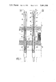
- FIG. 2 is a vertical sectional view of a portion of the device and shows the top fuse
- FIG. 3 is a view of the same device which is taken along the same section plane and shows the bottom fuse.
- FIG. 1 There are shown in FIG. 1 the emergency reactor shutdown system and the location of this latter within a liquid sodium cooled reactor.
- the reference 2 designates a fuel assembly which is enclosed in a known manner within a fuel can 4 in which are shown elements 8 of the top fertile blanket 6 of the reactor core and fuel pencils as designated by the reference 10 which constitute the reactor core 12 proper, provision being made beneath this latter for the bottom fertile blanket 14.
- the liquid sodium which constitutes the primary heat-transporting fluid is circulated in the upward direction within the fuel can 4.
- the emergency shutdown device 16 proper takes up the position of top fertile blanket elements of the reactor core and of fuel pencils. Said device is surrounded by a leak-tight casing tube 18 which has a portion of increased diameter at the level of the reactor core.
- said casing tube is advantageously made of stainless steel, has a hexagonal external cross-section and a circular internal cross-section and is filled with argon.
- Said casing tube 18 is rigidly fixed to the fuel assembly can 4 by means of a guide 20, for example, and by means of the grid which already serves to secure the fuel pencils.
- the emergency shutdown device is fitted at the top end with a fuse 22 which is sensitive to temperature.
- a stainless steel wire 24 is attached to said fuse and extends downwards to a level within the reactor core at which said wire supports a second fuse unit 26.
- a spacer tube 28, ten boron carbide elements such as the elements 30 and a steel ballast-weight 32 rest in this order on said second fuse 26.
- the fuse 22 which will be described in greater detail hereinafter is sensitive to temperature. In other words, when the temperature exceeds a preset threshold value, the fuse 22 melts and detaches the wire 24 from the casing tube 18. This accordingly releases the complete series of boron carbide masses 30 and the ballast-weight 32 which fall to the bottom 34 of the casing tube 18 as shown in FIG. 1a.
- the length of the spacer tube 28 is such that, in the position shown in FIG. 1a, the series of boron carbide masses is located at the level of the reactor core 12. Moreover, in the normal position, the fuse 26 is located in the central region of the reactor core. The necessary negative reactivity is thus introduced for shutdown of the reactor.
- the fuse 26 which will also be described below detaches the spacer tube 28 from the wire 24 when the neutron flux within the reactor core exceeds a predetermined threshold value. In this case, the spacer tube 28 becomes free with respect to the wire 24 and the complete assembly of boron carbide charges falls to the bottom 34 of the casing tube 18. It is readily apparent that in this position, the boron carbide charges 30 are also located at the level of the reactor core 12 at which the desired negative reactivity is introduced.
- the fuse 22 comprises a first element 36 constituted by a small calcium cylinder weighing approximately 20 grams.
- the cylinder 36 is rigidly fixed to the tube-wall 18 of the shutdown device by means of the necked portions 38 and 38'.
- the top extremity 40 of the wire 24 is anchored within the cylinder 36.
- Said cylinder is capable of supporting the charge which is fastened to the wire 24 without undergoing any creep deformation since the melting point of said cylinder (850°C) is well above the normal operating temperature of the reactor (560°C).
- the fuse 22 also comprises a second element 42 constituted by an aluminum ingot which is placed above the cylinder 36.
- the element 42 is rigidly fixed to the casing tube 18 by means of the necked portion 38 which forms a space 44 between these two members.
- the bottom fuse 26 has a first element 46 consisting of a calcium cylinder in which is anchored the lower extremity of the wire 24.
- the cylinder 46 is fitted on the bottom end-face thereof with a cup 48 which is made of stainless steel, for example.
- Said cup 48 is connected to the spacer tube 28 by means of tie-rods (not shown in the drawings) which are passed through the calcium cylinder 46.
- Said bottom fuse also has a second element consisting of a cylinder 50 which is pierced by an axial bore 51 and is progressively flared in the downward direction.
- the cylinder 50 is provided over the greater part of its length with fins such as the fin 52 and has a downward extension consisting of a sleeve 54 forming a cylindrical cavity 56 in which is placed the cylinder 46.
- the wire 24 and the spacer tube 28 are passed through the axial bore and the lower end of said spacer tube bears on the annular flange 58.
- the member 50 is advantageously made of aluminum.
- the sleeve 54 is formed of particles which generate heat under the action of the neutron flux.
- the operation of the bottom fuse is as follows. During normal operation (normal flux), the quantity of heat generated by the heating particles is small and is removed by the fins 52. The temperature at the level of the fuse is of the order of 500°C and the sleeve 54 has a temperature in the vicinity of 600°C. Doubling of the neutron flux causes the sleeve 54 to melt and to be separated from its fins 52. The temperature of the sleeve accordingly rises and the aluminum enters into reaction with the calcium as it falls into the cup 48. The reaction continues as indicated in the foregoing and the fuse releases the neutron-absorbing charge
- FIGS. 2 and 3 there are also shown the masses 30 of neutron-absorbing material and the steel ballast-weight 32 which are passed over the wire 24 by virtue of the axial bores such as the bore 59.
- the neutron-absorbing material is constituted by ten masses of 143 grams of boron carbide 100 % enriched in boron-10. Dropping of this charge into the reactor core produces a negative reactivity of approximately 600 milliniles.
- pairs of metals have a substantially identical action.
- Suitable pairs which can be mentioned by way of non-limitative example are calcium-barium or calcium-magnesium, in which it is noted that calcium always forms the support.
Landscapes
- Physics & Mathematics (AREA)
- Engineering & Computer Science (AREA)
- Plasma & Fusion (AREA)
- General Engineering & Computer Science (AREA)
- High Energy & Nuclear Physics (AREA)
- Structure Of Emergency Protection For Nuclear Reactors (AREA)
- Fuses (AREA)
Priority Applications (1)
| Application Number | Priority Date | Filing Date | Title |
|---|---|---|---|
| US05/662,911 US4076587A (en) | 1974-05-14 | 1976-03-01 | Fuse and application of said fuse to the construction of an emergency shutdown system for a nuclear reactor |
Applications Claiming Priority (2)
| Application Number | Priority Date | Filing Date | Title |
|---|---|---|---|
| FR73.18496 | 1973-05-22 | ||
| FR7318496A FR2230984B1 (zh) | 1973-05-22 | 1973-05-22 |
Related Child Applications (1)
| Application Number | Title | Priority Date | Filing Date |
|---|---|---|---|
| US05/662,911 Division US4076587A (en) | 1974-05-14 | 1976-03-01 | Fuse and application of said fuse to the construction of an emergency shutdown system for a nuclear reactor |
Publications (1)
| Publication Number | Publication Date |
|---|---|
| US3981598A true US3981598A (en) | 1976-09-21 |
Family
ID=9119737
Family Applications (1)
| Application Number | Title | Priority Date | Filing Date |
|---|---|---|---|
| US05/469,907 Expired - Lifetime US3981598A (en) | 1973-05-22 | 1974-05-14 | Fuse and application of said fuse to the construction of an emergency shutdown system for a nuclear reactor |
Country Status (4)
| Country | Link |
|---|---|
| US (1) | US3981598A (zh) |
| DE (1) | DE2424994C2 (zh) |
| FR (1) | FR2230984B1 (zh) |
| GB (1) | GB1447931A (zh) |
Cited By (9)
| Publication number | Priority date | Publication date | Assignee | Title |
|---|---|---|---|---|
| DE3222045A1 (de) * | 1982-06-11 | 1983-12-15 | Kernforschungsanlage Jülich GmbH, 5170 Jülich | Kernreaktor mit einer in abhaengigkeit vom neutronenfluss reagierenden abschalteinrichtung |
| US4452754A (en) * | 1982-01-20 | 1984-06-05 | The United States Of America As Represented By The United States Department Of Energy | Shutdown system for a nuclear reactor |
| US4470947A (en) * | 1981-12-30 | 1984-09-11 | The United States Of America As Represented By The United States Department Of Energy | Double-clad nuclear fuel safety rod |
| US4818477A (en) * | 1984-07-10 | 1989-04-04 | Westinghouse Electric Corp. | PCI resistant fuel and method and apparatus for controlling reactivity in a reactor core |
| US4842106A (en) * | 1987-10-08 | 1989-06-27 | Hughes Aircraft Company | Rate controllable damping mechanism |
| DE3249711C2 (en) * | 1982-06-11 | 1989-08-10 | Kernforschungsanlage Juelich Gmbh, 5170 Juelich, De | Nuclear reactor having a shutdown system which reacts as a function of the neutron flux |
| WO2013079662A1 (fr) * | 2011-12-02 | 2013-06-06 | Commissariat à l'énergie atomique et aux énergies alternatives | Assemblage pour reacteur nucleaire comportant du combustible nucleaire systeme de declenchement et d'insertion d'au moins un element absorbant neutronique et/ou mitigateur |
| US20130216016A1 (en) * | 2010-08-25 | 2013-08-22 | Commissariat A L'energie Atomique Et Aux Energies Alternatives | Device for Mitigating Serious Accidents for a Nuclear Fuel Assembly, With Improved Effectiveness |
| US11105526B1 (en) | 2017-09-29 | 2021-08-31 | Integrated Global Services, Inc. | Safety shutdown systems and methods for LNG, crude oil refineries, petrochemical plants, and other facilities |
Families Citing this family (3)
| Publication number | Priority date | Publication date | Assignee | Title |
|---|---|---|---|---|
| US4405558A (en) * | 1980-10-15 | 1983-09-20 | Westinghouse Electric Corp. | Nuclear reactor shutdown system |
| FR2505977A1 (fr) * | 1981-05-14 | 1982-11-19 | Commissariat Energie Atomique | Structure calorifuge pour dispositif de production de chaleur |
| FR2683667B1 (fr) * | 1991-11-08 | 1994-01-07 | Commissariat A Energie Atomique | Assemblage de combustible nucleaire a dispositif de securite passif integre. |
Citations (6)
| Publication number | Priority date | Publication date | Assignee | Title |
|---|---|---|---|---|
| US2764025A (en) * | 1953-07-14 | 1956-09-25 | Otto Walter | Thermal fuse |
| US2764026A (en) * | 1954-01-07 | 1956-09-25 | Otto Walter | Thermal fuse |
| US2866342A (en) * | 1956-10-09 | 1958-12-30 | Moorhead John Gerald | Heat-actuated motor |
| US2885893A (en) * | 1954-02-23 | 1959-05-12 | James A Lane | Reactor control mechanism |
| US2919236A (en) * | 1957-02-06 | 1959-12-29 | Walter H Zinn | Nuclear reactor including a package safety device |
| US3115453A (en) * | 1961-08-02 | 1963-12-24 | Paget John Arthur | Emergency shutdown for nuclear reactors |
-
1973
- 1973-05-22 FR FR7318496A patent/FR2230984B1/fr not_active Expired
-
1974
- 1974-05-10 GB GB2079174A patent/GB1447931A/en not_active Expired
- 1974-05-14 US US05/469,907 patent/US3981598A/en not_active Expired - Lifetime
- 1974-05-22 DE DE2424994A patent/DE2424994C2/de not_active Expired
Patent Citations (6)
| Publication number | Priority date | Publication date | Assignee | Title |
|---|---|---|---|---|
| US2764025A (en) * | 1953-07-14 | 1956-09-25 | Otto Walter | Thermal fuse |
| US2764026A (en) * | 1954-01-07 | 1956-09-25 | Otto Walter | Thermal fuse |
| US2885893A (en) * | 1954-02-23 | 1959-05-12 | James A Lane | Reactor control mechanism |
| US2866342A (en) * | 1956-10-09 | 1958-12-30 | Moorhead John Gerald | Heat-actuated motor |
| US2919236A (en) * | 1957-02-06 | 1959-12-29 | Walter H Zinn | Nuclear reactor including a package safety device |
| US3115453A (en) * | 1961-08-02 | 1963-12-24 | Paget John Arthur | Emergency shutdown for nuclear reactors |
Cited By (13)
| Publication number | Priority date | Publication date | Assignee | Title |
|---|---|---|---|---|
| US4470947A (en) * | 1981-12-30 | 1984-09-11 | The United States Of America As Represented By The United States Department Of Energy | Double-clad nuclear fuel safety rod |
| US4452754A (en) * | 1982-01-20 | 1984-06-05 | The United States Of America As Represented By The United States Department Of Energy | Shutdown system for a nuclear reactor |
| DE3249711C2 (en) * | 1982-06-11 | 1989-08-10 | Kernforschungsanlage Juelich Gmbh, 5170 Juelich, De | Nuclear reactor having a shutdown system which reacts as a function of the neutron flux |
| DE3222045A1 (de) * | 1982-06-11 | 1983-12-15 | Kernforschungsanlage Jülich GmbH, 5170 Jülich | Kernreaktor mit einer in abhaengigkeit vom neutronenfluss reagierenden abschalteinrichtung |
| US4818477A (en) * | 1984-07-10 | 1989-04-04 | Westinghouse Electric Corp. | PCI resistant fuel and method and apparatus for controlling reactivity in a reactor core |
| US4842106A (en) * | 1987-10-08 | 1989-06-27 | Hughes Aircraft Company | Rate controllable damping mechanism |
| US20130216016A1 (en) * | 2010-08-25 | 2013-08-22 | Commissariat A L'energie Atomique Et Aux Energies Alternatives | Device for Mitigating Serious Accidents for a Nuclear Fuel Assembly, With Improved Effectiveness |
| WO2013079662A1 (fr) * | 2011-12-02 | 2013-06-06 | Commissariat à l'énergie atomique et aux énergies alternatives | Assemblage pour reacteur nucleaire comportant du combustible nucleaire systeme de declenchement et d'insertion d'au moins un element absorbant neutronique et/ou mitigateur |
| FR2983624A1 (fr) * | 2011-12-02 | 2013-06-07 | Commissariat Energie Atomique | Assemblage pour reacteur nucleaire, comportant du combustible nucleaire et un systeme de declenchement et d'insertion d'au moins un element absorbant neutronique et/ou mitigateur |
| KR20140097452A (ko) * | 2011-12-02 | 2014-08-06 | 꼼미사리아 아 레네르지 아또미끄 에 오 에네르지 알떼르나띠브스 | 중성자를 흡수 및/또는 완화하는 적어도 하나의 요소를 촉발 및 삽입하기 위한 시스템 및 핵연료를 포함하는 핵원자로용 조립체 |
| CN104094358A (zh) * | 2011-12-02 | 2014-10-08 | 原子能和替代能源委员会 | 包括核燃料和用于触发和插入至少一个中子吸收元件和/或缓和元件的系统的用于核反应堆的组件 |
| US11105526B1 (en) | 2017-09-29 | 2021-08-31 | Integrated Global Services, Inc. | Safety shutdown systems and methods for LNG, crude oil refineries, petrochemical plants, and other facilities |
| US12007132B2 (en) | 2017-09-29 | 2024-06-11 | Integrated Global Services, Inc. | Safety shutdown systems and methods for LNG, crude oil refineries, petrochemical plants, and other facilities |
Also Published As
| Publication number | Publication date |
|---|---|
| DE2424994A1 (de) | 1974-12-12 |
| GB1447931A (en) | 1976-09-02 |
| FR2230984A1 (zh) | 1974-12-20 |
| DE2424994C2 (de) | 1983-06-16 |
| FR2230984B1 (zh) | 1976-04-23 |
Similar Documents
| Publication | Publication Date | Title |
|---|---|---|
| US3981598A (en) | Fuse and application of said fuse to the construction of an emergency shutdown system for a nuclear reactor | |
| US4076587A (en) | Fuse and application of said fuse to the construction of an emergency shutdown system for a nuclear reactor | |
| US3197381A (en) | Nuclear reactor fuel elements | |
| US10643755B2 (en) | Device for passive protection of a nuclear reactor | |
| US20130216016A1 (en) | Device for Mitigating Serious Accidents for a Nuclear Fuel Assembly, With Improved Effectiveness | |
| JP6181067B2 (ja) | 核燃料と、少なくとも1つの中性子吸収および/または緩和要素を起動し挿入するシステムとを備えた原子炉用集合体 | |
| GB857959A (en) | Power breeder reactor | |
| US3580809A (en) | Nuclear reactor fuel element with spaced reductions of diameter | |
| US3677892A (en) | Collecting device for cooling reactor core fragments in a fast breeder reactor | |
| KR20140097551A (ko) | 핵 원자로의 분열 영역에 흡수 부재 및/또는 완화제를 촉발 및 삽입하는 장치 및 그러한 장치를 포함하는 핵연료 조립체 | |
| US2919236A (en) | Nuclear reactor including a package safety device | |
| US3115453A (en) | Emergency shutdown for nuclear reactors | |
| US3118819A (en) | Nuclear fuel cartridge | |
| US3932217A (en) | Method and device for the passive protection of a nuclear reactor | |
| CN106941013B (zh) | 触发与插入设备及系统、核燃料组件、核反应堆 | |
| US3446703A (en) | Method of operating a nuclear reactor | |
| RU2173484C1 (ru) | Быстрый реактор с тяжелым жидкометаллическим теплоносителем | |
| US4470947A (en) | Double-clad nuclear fuel safety rod | |
| US3795580A (en) | Fuse for nuclear reactor | |
| US3249510A (en) | Shutdown apparatus for nuclear reactors | |
| US3507748A (en) | Control and safety device for nuclear reactors | |
| US3085060A (en) | Nuclear reactor safety device | |
| RU2179751C1 (ru) | Тепловыделяющий элемент | |
| RU2027233C1 (ru) | Экспериментальное ампульное устройство | |
| Dickerman et al. | In-pile experiments on meltdown of EBR-II Mark I fuel elements in stagnant sodium |