US3972097A - Tool for attachment to the dipper arm of an excavator - Google Patents
Tool for attachment to the dipper arm of an excavator Download PDFInfo
- Publication number
- US3972097A US3972097A US05/513,764 US51376474A US3972097A US 3972097 A US3972097 A US 3972097A US 51376474 A US51376474 A US 51376474A US 3972097 A US3972097 A US 3972097A
- Authority
- US
- United States
- Prior art keywords
- arm
- extension member
- free end
- dipper arm
- dipper
- Prior art date
- Legal status (The legal status is an assumption and is not a legal conclusion. Google has not performed a legal analysis and makes no representation as to the accuracy of the status listed.)
- Expired - Lifetime
Links
- 238000010008 shearing Methods 0.000 claims abstract 3
- 238000004519 manufacturing process Methods 0.000 description 1
- 238000012986 modification Methods 0.000 description 1
- 230000004048 modification Effects 0.000 description 1
Images

Classifications
-
- E—FIXED CONSTRUCTIONS
- E02—HYDRAULIC ENGINEERING; FOUNDATIONS; SOIL SHIFTING
- E02F—DREDGING; SOIL-SHIFTING
- E02F3/00—Dredgers; Soil-shifting machines
- E02F3/04—Dredgers; Soil-shifting machines mechanically-driven
- E02F3/28—Dredgers; Soil-shifting machines mechanically-driven with digging tools mounted on a dipper- or bucket-arm, i.e. there is either one arm or a pair of arms, e.g. dippers, buckets
- E02F3/36—Component parts
- E02F3/40—Dippers; Buckets ; Grab devices, e.g. manufacturing processes for buckets, form, geometry or material of buckets
- E02F3/413—Dippers; Buckets ; Grab devices, e.g. manufacturing processes for buckets, form, geometry or material of buckets with grabbing device
- E02F3/4135—Dippers; Buckets ; Grab devices, e.g. manufacturing processes for buckets, form, geometry or material of buckets with grabbing device with grabs mounted directly on a boom
-
- E—FIXED CONSTRUCTIONS
- E02—HYDRAULIC ENGINEERING; FOUNDATIONS; SOIL SHIFTING
- E02F—DREDGING; SOIL-SHIFTING
- E02F3/00—Dredgers; Soil-shifting machines
- E02F3/04—Dredgers; Soil-shifting machines mechanically-driven
- E02F3/28—Dredgers; Soil-shifting machines mechanically-driven with digging tools mounted on a dipper- or bucket-arm, i.e. there is either one arm or a pair of arms, e.g. dippers, buckets
- E02F3/36—Component parts
- E02F3/40—Dippers; Buckets ; Grab devices, e.g. manufacturing processes for buckets, form, geometry or material of buckets
- E02F3/402—Dippers; Buckets ; Grab devices, e.g. manufacturing processes for buckets, form, geometry or material of buckets with means for facilitating the loading thereof, e.g. conveyors
- E02F3/404—Dippers; Buckets ; Grab devices, e.g. manufacturing processes for buckets, form, geometry or material of buckets with means for facilitating the loading thereof, e.g. conveyors comprising two parts movable relative to each other, e.g. for gripping
-
- E—FIXED CONSTRUCTIONS
- E02—HYDRAULIC ENGINEERING; FOUNDATIONS; SOIL SHIFTING
- E02F—DREDGING; SOIL-SHIFTING
- E02F3/00—Dredgers; Soil-shifting machines
- E02F3/04—Dredgers; Soil-shifting machines mechanically-driven
- E02F3/96—Dredgers; Soil-shifting machines mechanically-driven with arrangements for alternate or simultaneous use of different digging elements
- E02F3/963—Arrangements on backhoes for alternate use of different tools
-
- Y—GENERAL TAGGING OF NEW TECHNOLOGICAL DEVELOPMENTS; GENERAL TAGGING OF CROSS-SECTIONAL TECHNOLOGIES SPANNING OVER SEVERAL SECTIONS OF THE IPC; TECHNICAL SUBJECTS COVERED BY FORMER USPC CROSS-REFERENCE ART COLLECTIONS [XRACs] AND DIGESTS
- Y10—TECHNICAL SUBJECTS COVERED BY FORMER USPC
- Y10T—TECHNICAL SUBJECTS COVERED BY FORMER US CLASSIFICATION
- Y10T29/00—Metal working
- Y10T29/51—Plural diverse manufacturing apparatus including means for metal shaping or assembling
Definitions
- the present invention relates to a tool for attachment to the dipper arm of a hydraulic excavator for processing scrap automobiles.
- a tool for attachment to the dipper arm of a hydraulic excavator for processing scrap automobiles In order to be able to convey scrap automobiles to a scrap press, it was heretofore customary for purposes of first removing non-metallic parts, especially upholstered parts and tires, to employ human work forces because the customary working tools as for instance hydraulic excavators, attachments, etc., have not proved suitable to enter the bodies or to remove rubber tires from the rims in view of the relatively small surfaces.
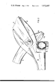
- FIG. 1 shows the side view of a grab with dipper arm.
- FIG. 2 is a side view of the cutting device for tires and forms a cut-out of FIG. 1 but on a larger scale than the latter.
- the tool according to the present invention is characterized primarily in that an extension member is firmly connected to the dipper arm and projects beyond the free end of said dipper arm, said extension member cooperating in the manner of a shear or grab with a ripping tooth which is rotatably linked to the free end of the dipper arm.
- the ripping tooth cooperates with the extension member firmly connected to the dipper arm. At that end thereof adjacent its pivot point, the same extends beyond the pivot point by means of a wing provided with a cutting edge.
- the wing in turn cooperates in a shear-like manner with that side of the extension member which faces away from the ripping tooth.
- the arrangement shown therein comprises a boom 1 on a non-illustrated hydraulic excavator.
- the arrangement shown in the drawing furthermore comprises a dipper arm 2 which in the pivot point 3 is pivotable by means of the hydraulic cylinder 4 a vertical plane.
- a ripping tooth 5 which is pivotally mounted in the pivot 6 and by means of the hydraulic cylinder 7 journaled in the dipper arm and more specifically in the fixed point 7a thereof, is actuated by means of the levers 8 and 9.
- the extension member 10 is connected to the free end of the dipper arm.
- the ripping tooth 5 at that end thereof which is adjacent to the pivot point is extended by a wing 11 which forms one piece with the ripping tooth 5.
- the wing 11 at that end thereof which faces the extension member 10 is provided with a cutting edge 11a.
- the extension member 10 at that side which faces the wing 11 is provided with a semicircular counter edge 12 which forms the counter cutting edge to the cutting edge 11a of the wing 11.
- the ripping tooth 5 When actuating the ripping tooth 5 by means of the hydraulic cylinder 7, the ripping tooth 5 will be able when occupying the dash-line position in which the extension member 10 forms the counter-bearing to the ripping tooth 5, to grasp articles in a plier-like manner and tear the same out, for instance upholstered parts from scrap automobiles.
- the rubber tires of scrap automobiles, by means of the scissor-like arrangement 11, 11a, 12 can be cut as shown in FIG. 2 so that the rubber tires drop off from the rims.
Abstract
A tool forming an attachment to the dipper arm of an excavator, especially for processing scrap automobiles, which includes an extension member that is fixedly connected to the dipper arm and projects beyond the free end portion of the latter. The free end portion of this extension member forms a gripping and shearing structure with a ripping tooth member which preferably forms a two-arm lever pivotally supported by the free outer end of the dipper arm. The longer arm of the two-arm lever cooperates with the extension member while forming a gripping device therewith, whereas the shorter arm of the two-arm lever cooperates with a shearing member supported by the extension member and forms a shear therewith.
Description
The present invention relates to a tool for attachment to the dipper arm of a hydraulic excavator for processing scrap automobiles. In order to be able to convey scrap automobiles to a scrap press, it was heretofore customary for purposes of first removing non-metallic parts, especially upholstered parts and tires, to employ human work forces because the customary working tools as for instance hydraulic excavators, attachments, etc., have not proved suitable to enter the bodies or to remove rubber tires from the rims in view of the relatively small surfaces.
It is, therefore, an object of the present invention to make a device which is made in mass production and is hydraulically driven, especially a customary hydraulic excavator with simple means, which will be suitable for carrying out the above mentioned operations.
This object and other objects and advantages of the invention will appear more clearly from the following specification in connection with the accompanying drawings, in which:
FIG. 1 shows the side view of a grab with dipper arm. FIG. 2 is a side view of the cutting device for tires and forms a cut-out of FIG. 1 but on a larger scale than the latter.
The tool according to the present invention is characterized primarily in that an extension member is firmly connected to the dipper arm and projects beyond the free end of said dipper arm, said extension member cooperating in the manner of a shear or grab with a ripping tooth which is rotatably linked to the free end of the dipper arm.
According to a further development of the invention, the ripping tooth cooperates with the extension member firmly connected to the dipper arm. At that end thereof adjacent its pivot point, the same extends beyond the pivot point by means of a wing provided with a cutting edge. The wing in turn cooperates in a shear-like manner with that side of the extension member which faces away from the ripping tooth.
Referring now to the drawings in detail, the arrangement shown therein comprises a boom 1 on a non-illustrated hydraulic excavator. The arrangement shown in the drawing furthermore comprises a dipper arm 2 which in the pivot point 3 is pivotable by means of the hydraulic cylinder 4 a vertical plane. At the free end of the dipper arm 2 there is provided a ripping tooth 5 which is pivotally mounted in the pivot 6 and by means of the hydraulic cylinder 7 journaled in the dipper arm and more specifically in the fixed point 7a thereof, is actuated by means of the levers 8 and 9. On that side of the dipper arm 2 which faces away from the hydraulic cylinder 7, the extension member 10 is connected to the free end of the dipper arm.
The ripping tooth 5 at that end thereof which is adjacent to the pivot point is extended by a wing 11 which forms one piece with the ripping tooth 5. The wing 11 at that end thereof which faces the extension member 10 is provided with a cutting edge 11a. The extension member 10 at that side which faces the wing 11 is provided with a semicircular counter edge 12 which forms the counter cutting edge to the cutting edge 11a of the wing 11.
When actuating the ripping tooth 5 by means of the hydraulic cylinder 7, the ripping tooth 5 will be able when occupying the dash-line position in which the extension member 10 forms the counter-bearing to the ripping tooth 5, to grasp articles in a plier-like manner and tear the same out, for instance upholstered parts from scrap automobiles. The rubber tires of scrap automobiles, by means of the scissor- like arrangement 11, 11a, 12 can be cut as shown in FIG. 2 so that the rubber tires drop off from the rims.
It is, of course, to be understood, that the present invention is, by no means, limited to the specific showing in the drawings but also comprises any modifications within the scope of the appended claims.
Claims (1)
1. In combination with a dipper arm having a free end portion and forming part of an excavator, a tool including an extension member fixedly connected to said dipper arm and projecting beyond said free end portion of said dipper arm and having an outer free end, ripping tooth means rotatably supported by said free end portion of said dipper arm, and together with said extension member forming a gripping and shearing structure simultaneously, power operable means supported by said dipper arm and operatively connected to said ripping tooth means for selectively pivoting said ripping tooth means toward and away from said extension member, said ripping tooth means forming a two-arm lever having a longer arm for cooperation with the outer free end of said extension member and also having a shorter arm, first shear means supported by said extension member and in operative position facing said shorter arm, and second shear means supported by said shorter arm for cooperation with said first shear means in response to the pivoting of said shorter arm toward said first shear means.
Priority Applications (1)
| Application Number | Priority Date | Filing Date | Title |
|---|---|---|---|
| US05/513,764 US3972097A (en) | 1974-10-10 | 1974-10-10 | Tool for attachment to the dipper arm of an excavator |
Applications Claiming Priority (1)
| Application Number | Priority Date | Filing Date | Title |
|---|---|---|---|
| US05/513,764 US3972097A (en) | 1974-10-10 | 1974-10-10 | Tool for attachment to the dipper arm of an excavator |
Publications (1)
| Publication Number | Publication Date |
|---|---|
| US3972097A true US3972097A (en) | 1976-08-03 |
Family
ID=24044594
Family Applications (1)
| Application Number | Title | Priority Date | Filing Date |
|---|---|---|---|
| US05/513,764 Expired - Lifetime US3972097A (en) | 1974-10-10 | 1974-10-10 | Tool for attachment to the dipper arm of an excavator |
Country Status (1)
| Country | Link |
|---|---|
| US (1) | US3972097A (en) |
Cited By (18)
| Publication number | Priority date | Publication date | Assignee | Title |
|---|---|---|---|---|
| DE2755604A1 (en) * | 1977-01-21 | 1978-07-27 | Labounty Roy E | TIRE REMOVAL DEVICE |
| US4188721A (en) * | 1978-11-02 | 1980-02-19 | Ramun John R | Attachment for a back hoe |
| US4198747A (en) * | 1978-11-22 | 1980-04-22 | Labounty Roy E | Hydraulic shear |
| US4285629A (en) * | 1978-05-18 | 1981-08-25 | Elliston Thomas L | Fire fighting boom assembly for service vessel |
| DE3201328A1 (en) * | 1981-05-07 | 1982-11-25 | John 44502 Youngstown Ohio Ramun | CUTTING AND ACTUATING DEVICE FOR A LOEFFEL EXCAVATOR |
| US4392263A (en) * | 1981-02-02 | 1983-07-12 | Amoroso Michael J | Portable rescue tool |
| US4558515A (en) * | 1982-09-13 | 1985-12-17 | Labounty Roy E | Metal grapple shear |
| US4771540A (en) * | 1982-09-13 | 1988-09-20 | Labounty Roy E | Metal grapple shear |
| US4804309A (en) * | 1987-10-01 | 1989-02-14 | Risch Joel V | Gripping device for boom-mounted work tool |
| US4838493A (en) * | 1988-06-10 | 1989-06-13 | Labounty Kenneth R | Concrete crusher |
| US4872264A (en) * | 1988-01-11 | 1989-10-10 | Labounty Roy E | Heavy duty plate shear |
| US5044569A (en) * | 1989-12-15 | 1991-09-03 | Labounty Roy E | Rock and coral demolition tool |
| US5060378A (en) * | 1989-12-15 | 1991-10-29 | Labounty Manufacturing, Inc. | Demolition tool for a hydraulic excavator |
| US5142779A (en) * | 1991-12-02 | 1992-09-01 | Labounty Manufacturing, Inc. | Mobile wood and tire shear |
| US20040261301A1 (en) * | 2003-06-30 | 2004-12-30 | Vering Andrew L. | High rotation linkage assembly |
| WO2006123934A2 (en) * | 2005-05-20 | 2006-11-23 | Rolls-Royce Marine As | Crane for handling of chains, wires, etc., and tools for same |
| US20070180740A1 (en) * | 2006-02-09 | 2007-08-09 | Crowley John Jr | Dipper stick cutter |
| US7818901B2 (en) | 2007-09-21 | 2010-10-26 | Acs Industries, Inc. | Progressive linkage for excavator thumb |
Citations (4)
| Publication number | Priority date | Publication date | Assignee | Title |
|---|---|---|---|---|
| US245122A (en) * | 1881-08-02 | George w | ||
| US638116A (en) * | 1898-12-14 | 1899-11-28 | Edmond J Lonergan | Pruning implement. |
| US3275172A (en) * | 1965-05-04 | 1966-09-27 | Wrex All Implements Inc | Wrecking and loading tool for use with a back hoe |
| US3550655A (en) * | 1968-07-05 | 1970-12-29 | Case Co J I | Torque-absorbing coupler |
-
1974
- 1974-10-10 US US05/513,764 patent/US3972097A/en not_active Expired - Lifetime
Patent Citations (4)
| Publication number | Priority date | Publication date | Assignee | Title |
|---|---|---|---|---|
| US245122A (en) * | 1881-08-02 | George w | ||
| US638116A (en) * | 1898-12-14 | 1899-11-28 | Edmond J Lonergan | Pruning implement. |
| US3275172A (en) * | 1965-05-04 | 1966-09-27 | Wrex All Implements Inc | Wrecking and loading tool for use with a back hoe |
| US3550655A (en) * | 1968-07-05 | 1970-12-29 | Case Co J I | Torque-absorbing coupler |
Cited By (27)
| Publication number | Priority date | Publication date | Assignee | Title |
|---|---|---|---|---|
| DE2755604A1 (en) * | 1977-01-21 | 1978-07-27 | Labounty Roy E | TIRE REMOVAL DEVICE |
| US4104792A (en) * | 1977-01-21 | 1978-08-08 | Labounty Roy E | Wheel and tire cutter |
| US4285629A (en) * | 1978-05-18 | 1981-08-25 | Elliston Thomas L | Fire fighting boom assembly for service vessel |
| US4188721A (en) * | 1978-11-02 | 1980-02-19 | Ramun John R | Attachment for a back hoe |
| US4198747A (en) * | 1978-11-22 | 1980-04-22 | Labounty Roy E | Hydraulic shear |
| US4392263A (en) * | 1981-02-02 | 1983-07-12 | Amoroso Michael J | Portable rescue tool |
| DE3201328A1 (en) * | 1981-05-07 | 1982-11-25 | John 44502 Youngstown Ohio Ramun | CUTTING AND ACTUATING DEVICE FOR A LOEFFEL EXCAVATOR |
| US4558515A (en) * | 1982-09-13 | 1985-12-17 | Labounty Roy E | Metal grapple shear |
| US4771540A (en) * | 1982-09-13 | 1988-09-20 | Labounty Roy E | Metal grapple shear |
| US4804309A (en) * | 1987-10-01 | 1989-02-14 | Risch Joel V | Gripping device for boom-mounted work tool |
| US4872264A (en) * | 1988-01-11 | 1989-10-10 | Labounty Roy E | Heavy duty plate shear |
| US4838493A (en) * | 1988-06-10 | 1989-06-13 | Labounty Kenneth R | Concrete crusher |
| US5044569A (en) * | 1989-12-15 | 1991-09-03 | Labounty Roy E | Rock and coral demolition tool |
| US5060378A (en) * | 1989-12-15 | 1991-10-29 | Labounty Manufacturing, Inc. | Demolition tool for a hydraulic excavator |
| USRE35432E (en) * | 1989-12-15 | 1997-01-28 | Labounty Manufacturing Co. | Demolition tool for a hydraulic excavator |
| US5142779A (en) * | 1991-12-02 | 1992-09-01 | Labounty Manufacturing, Inc. | Mobile wood and tire shear |
| US20040261301A1 (en) * | 2003-06-30 | 2004-12-30 | Vering Andrew L. | High rotation linkage assembly |
| GB2454988A (en) * | 2005-05-20 | 2009-05-27 | Rolls Royce Marine As | Tools for handling chains, wires, shackles, etc. |
| WO2006123934A3 (en) * | 2005-05-20 | 2007-01-25 | Rolls Royce Marine As | Crane for handling of chains, wires, etc., and tools for same |
| GB2441468A (en) * | 2005-05-20 | 2008-03-05 | Rolls Royce Marine As | Crane for handling of chains, wires, etc. and tools for same |
| GB2441468B (en) * | 2005-05-20 | 2009-04-29 | Rolls Royce Marine As | Tool for handling wires |
| WO2006123934A2 (en) * | 2005-05-20 | 2006-11-23 | Rolls-Royce Marine As | Crane for handling of chains, wires, etc., and tools for same |
| GB2454988B (en) * | 2005-05-20 | 2009-09-30 | Rolls Royce Marine As | Crane for handling of chains,wires, etc |
| US20090301983A1 (en) * | 2005-05-20 | 2009-12-10 | Johnny Lorgen | Crane for handling of chains,wires,etc., and tools for same |
| US20070180740A1 (en) * | 2006-02-09 | 2007-08-09 | Crowley John Jr | Dipper stick cutter |
| US7628185B2 (en) | 2006-02-09 | 2009-12-08 | Crowley Jr John | Dipper stick cutter |
| US7818901B2 (en) | 2007-09-21 | 2010-10-26 | Acs Industries, Inc. | Progressive linkage for excavator thumb |
Similar Documents
| Publication | Publication Date | Title |
|---|---|---|
| US3972097A (en) | Tool for attachment to the dipper arm of an excavator | |
| US5438772A (en) | Tool for implements | |
| EP0404229B1 (en) | Device for breaking objects consisting of concrete or similar material | |
| US4198747A (en) | Hydraulic shear | |
| JPH079970Y2 (en) | Steel cutting machine | |
| US4771540A (en) | Metal grapple shear | |
| US5142779A (en) | Mobile wood and tire shear | |
| WO2000054916B1 (en) | Heavy duty demolition apparatus with replaceable crushing and shearing tip | |
| US3275172A (en) | Wrecking and loading tool for use with a back hoe | |
| JPH0248708B2 (en) | ||
| US4466494A (en) | Implement with gripping arm assembly for a backhoe | |
| CA2154332A1 (en) | Compound Action Hand Pruner | |
| JPS6217059B2 (en) | ||
| GB2071053A (en) | Improved grapple and shear assembly | |
| US3999315A (en) | Adjustable attachment for a backhoe | |
| GB1499015A (en) | Suction head for the suction pipe of a suction dredger | |
| GB1478701A (en) | Tool for removing scrap materials from scrap cars | |
| DE20218497U1 (en) | Hydraulic additive apparatus for incorporation on excavator, crane, hydraulic hammer and similar work machines is provided with steel cutter | |
| GB1499329A (en) | Apparatus for breaking up a layer of substantially rigid material | |
| JP7402559B1 (en) | earthmoving machine attachments | |
| JPH0747464Y2 (en) | Grapple | |
| JPH0738569Y2 (en) | Dismantling device | |
| JPS5914597Y2 (en) | Crushing machine | |
| GB1378175A (en) | Metal-shearing machines | |
| JPS588415Y2 (en) | steel plate cutting machine |