US396035A - Lathe chuck - Google Patents
Lathe chuck Download PDFInfo
- Publication number
- US396035A US396035A US396035DA US396035A US 396035 A US396035 A US 396035A US 396035D A US396035D A US 396035DA US 396035 A US396035 A US 396035A
- Authority
- US
- United States
- Prior art keywords
- jaws
- blocks
- chuck
- block
- shell
- Prior art date
- Legal status (The legal status is an assumption and is not a legal conclusion. Google has not performed a legal analysis and makes no representation as to the accuracy of the status listed.)
- Expired - Lifetime
Links
- 210000001847 Jaw Anatomy 0.000 description 42
- 230000004048 modification Effects 0.000 description 4
- 238000006011 modification reaction Methods 0.000 description 4
- 210000003800 Pharynx Anatomy 0.000 description 2
Images

Classifications
-
- B—PERFORMING OPERATIONS; TRANSPORTING
- B23—MACHINE TOOLS; METAL-WORKING NOT OTHERWISE PROVIDED FOR
- B23B—TURNING; BORING
- B23B31/00—Chucks; Expansion mandrels; Adaptations thereof for remote control
- B23B31/02—Chucks
- B23B31/10—Chucks characterised by the retaining or gripping devices or their immediate operating means
- B23B31/12—Chucks with simultaneously-acting jaws, whether or not also individually adjustable
- B23B31/16—Chucks with simultaneously-acting jaws, whether or not also individually adjustable moving radially
- B23B31/16195—Jaws movement actuated by levers moved by a coaxial control rod
-
- Y—GENERAL TAGGING OF NEW TECHNOLOGICAL DEVELOPMENTS; GENERAL TAGGING OF CROSS-SECTIONAL TECHNOLOGIES SPANNING OVER SEVERAL SECTIONS OF THE IPC; TECHNICAL SUBJECTS COVERED BY FORMER USPC CROSS-REFERENCE ART COLLECTIONS [XRACs] AND DIGESTS
- Y10—TECHNICAL SUBJECTS COVERED BY FORMER USPC
- Y10T—TECHNICAL SUBJECTS COVERED BY FORMER US CLASSIFICATION
- Y10T279/00—Chucks or sockets
- Y10T279/19—Radially reciprocating jaws
- Y10T279/1953—Toggle actuated
Definitions
- DORR E. FELT OF CHICAGO
- ILLINOIS ASSIGNOR OF ONE-FOI RTII TO ROBERT TARRANT, OF SAME PLACE.
- FIG. 1 is a vertical central section showing the jaws in their closed position.
- Fig. 2 is a vertical section showing the jaws partly open.
- Fig. 3 is a front view of the face-plate.
- Fig. at is a front view of the chuck, the faceplate being removed.
- Fig. 5 is a modification showing an adjusting device different from that shown in Figs. 1 and 2.
- Fig. 6 is a front view of the chuck shown in Fig.
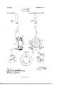
- Fig. 7 is a side elevation with an operating-lever attached.
- Fig. 8 is a rear elevation.
- Figs. 9 and 10 are details showing an edge view and a front view of one of the movable jaws shown in Figs. 1, 2, and 4-.
- Fig. 11 is a front view of a faceplate which is to be applied to the chuck when disks are to be held thereby, instead of wire or small rods.
- Figs. 12 and 13 represent a jaw different from the jaws shown in Figs. 1, 2, and l, and adapted to be clamped upon the edge of a disk.
- My improvement relates to that class of chucks which are designed to be rotated continuously while the work is being done, and which do not have to be stopped as often as each piece has been completed.
- the leading objects of my invention are to provide improved devices for clamping the article to be operated upon, which can be easily operated, and in the use of which there will be but little friction on any of the parts, which I accomplish as illustrated in the drawings, and hereinafter described.
- A represents the shell of the chuck.
- I is the head or body.
- each block I there is a similar groove or recess, 1).
- c is a toggle-link, the. ends of which are formed to fit into the recesses a. l).
- e are slots in the shell A, one for each block D.
- f are cap-screws, one for each block D.
- E is a face-plate provided with holes g to receive screws, by means of which the plate is fastened to the head or bodyB.
- This plate is also provided with three holes, 72, to receive the ends of dowel-pins 1', which are secured in the plate, and are inserted in holes in the body B.
- j are screw-holes in the body B.
- k is a pin, which is secured in the shell A, the inner end of which extends into a groove in the head or body B.
- F is the operating-lever, arranged snbstam tially as usual.
- Figs. 9 and 10 represent jaws such as are shown in Figs. 1, 2, and i, and which are designed to clamp a piece of wire or rod.
- Figs. 12 and 13 show a jaw, G, adapted to be used for clamping disks.
- ⁇ Yhen jaws like G are used, the face-plate is to be provided with slots 11 to receive the jaws.
- ⁇ Vhen the jaws G are used, they are provided with recesses a to receive the toggle-link c, the same as before described, and blocks D are used in connection therewith.
- the blocks and jaws can be adjusted for different sizes of wire by means of the setscrews d, and when adjusted the blocks D can be secured in position by means of the cap-screws f. p
- Figs. 5 and (3 l have shown a nioditiea- 5 tion which relates to the manner of adjusting i the blocks 1), which is accomplished by bevcling one side, o, of each block and by providing a screw, p, for each block, which screw provided with a head, q, beveled on the in- E side to engage with the bevel 0 on the block D.
- the block 'I By changing the position of the screw 1) the block 'I) can be raised or lowered a little, carrying with it the jaw connected therewith, and when ln-ougl'it to proper position the block I 5 can be secured in place by the screw f, as be fore described. This modification in no way affects the operation of the device.
- the body is cut away to receive the blocks 3 l), and is thus weakened; but the taeeiilate, i being secured to the body by the screws and l dowel-pins, materially strengthens the body. i
Landscapes
- Engineering & Computer Science (AREA)
- Mechanical Engineering (AREA)
- Manipulator (AREA)
- Gripping On Spindles (AREA)
Description
(No Model.)
' 2 Sheet-Sheet '1. D. E. FELT.
LATHE CHUCK.
Patented Jan. 8, 1889.
1 naw/M00.
N PETERS. Phdlwli'hflgmpher, Washingkm. E C.
(No Model.) 7 2 s eets-sneer. 2. D. E. FELT.
LATHE GHUGK No. 396,035. Patente wibvmomw n PETERS. mwmum w, Wailingloll. n. c,
UNITED STATES ATENT Fries.
DORR E. FELT, OF CHICAGO, ILLINOIS, ASSIGNOR OF ONE-FOI RTII TO ROBERT TARRANT, OF SAME PLACE.
LATHE-CHUCK.
SPECIFICATION forming part of Letters Patent No. 396,035, dated January 8, 1889.
Application filed June 4, 1888.
To aZZ whom it may concern:
Be it known that I, DORR E. FELT, residing at Chicago, in the county of Cook and State of Illinois, and a citizen of the United States, have invented a new and useful Improvement in ire-Feed Chucks, of which the following is a specification, reference being had to the accompanying drawings, in which Figure l is a vertical central section showing the jaws in their closed position. Fig. 2 is a vertical section showing the jaws partly open. Fig. 3 is a front view of the face-plate. Fig. at is a front view of the chuck, the faceplate being removed. Fig. 5 is a modification showing an adjusting device different from that shown in Figs. 1 and 2. Fig. 6 is a front view of the chuck shown in Fig. 5, the faceplate being removed. Fig. 7 is a side elevation with an operating-lever attached. Fig. 8 is a rear elevation. Figs. 9 and 10 are details showing an edge view and a front view of one of the movable jaws shown in Figs. 1, 2, and 4-. Fig. 11 is a front view of a faceplate which is to be applied to the chuck when disks are to be held thereby, instead of wire or small rods. Figs. 12 and 13 represent a jaw different from the jaws shown in Figs. 1, 2, and l, and adapted to be clamped upon the edge of a disk.
My improvement relates to that class of chucks which are designed to be rotated continuously while the work is being done, and which do not have to be stopped as often as each piece has been completed.
The leading objects of my invention are to provide improved devices for clamping the article to be operated upon, which can be easily operated, and in the use of which there will be but little friction on any of the parts, which I accomplish as illustrated in the drawings, and hereinafter described.
Thatwhich I elaim as new will be pointed out in the claims.
In the drawings, A represents the shell of the chuck.
I; is the head or body.
0 are jaws, which are fitted into grooves in I the head I There are three of these jaws.
I) is a block fitted into a recess in the shell A, and it extends into a groove in the body B of the chuck. In each jaw there is a circular 1 seal ND. 276,049. ea model.)
' groove or recess, a, the throat of which is contracted. In the side of each block I) there is a similar groove or recess, 1).
c is a toggle-link, the. ends of which are formed to fit into the recesses a. l).
(Z are adjusting-screws, one for each block D.
e are slots in the shell A, one for each block D.
f are cap-screws, one for each block D.
E is a face-plate provided with holes g to receive screws, by means of which the plate is fastened to the head or bodyB. This plate is also provided with three holes, 72, to receive the ends of dowel-pins 1', which are secured in the plate, and are inserted in holes in the body B.
j are screw-holes in the body B.
k is a pin, which is secured in the shell A, the inner end of which extends into a groove in the head or body B.
F is the operating-lever, arranged snbstam tially as usual.
Z, Fig. 8, are blocks which enter a groove, m, in the shell A, which are pivoted to the lever F.
It is common to provide two sets of jaws for chucks of this class, one to be used for holding wire and the other to be used for holding disks.
Figs. 9 and 10 represent jaws such as are shown in Figs. 1, 2, and i, and which are designed to clamp a piece of wire or rod.
Figs. 12 and 13 show a jaw, G, adapted to be used for clamping disks. \Yhen jaws like G are used, the face-plate is to be provided with slots 11 to receive the jaws. \Vhen the jaws G are used, they are provided with recesses a to receive the toggle-link c, the same as before described, and blocks D are used in connection therewith.
In use, when the parts are in the position shown in Fig. l, the jaws will be clamped upon the wire which is being operated upon.
By moving the lever F a little the shellA can be brought into the position shown in Fig. 2, moving the blocks 1) back with the shell A and separating the jaws su fficient to allow the wire to be fed forward. The blocks and the jaws are connected by means of the toggle links, so that the jaws are moved by the movements of the blocks.
The blocks and jaws can be adjusted for different sizes of wire by means of the setscrews d, and when adjusted the blocks D can be secured in position by means of the cap-screws f. p
In Figs. 5 and (3 l have shown a nioditiea- 5 tion which relates to the manner of adjusting i the blocks 1), which is accomplished by bevcling one side, o, of each block and by providing a screw, p, for each block, which screw provided with a head, q, beveled on the in- E side to engage with the bevel 0 on the block D. By changing the position of the screw 1) the block 'I) can be raised or lowered a little, carrying with it the jaw connected therewith, and when ln-ougl'it to proper position the block I 5 can be secured in place by the screw f, as be fore described. This modification in no way affects the operation of the device.
The body is cut away to receive the blocks 3 l), and is thus weakened; but the taeeiilate, i being secured to the body by the screws and l dowel-pins, materially strengthens the body. i
"What I claim as new, and desire to secure by Letters Patent, is-- 1. In combination with a shell, A, and body B, jaws for holding a wire or disk, adjustable blocks 1'), toggle-links c, t'aee-plate E, screws for adjusting the blocks 1), and set-screws f, for holding the blocks 1) in their adjusted position, substantially as and for the purpose specified.
2. In a chuck, the combination of a shell, A, and body 1 with holding-jaws, adjustable blocks 1), toggledinks c, face-plate E, and dowel-pins i, substantially as and for the purpose specified.
DORR E. FELT.
\V i t'nesses:
ALBERT II. ADAMS, HARRY Tl. J'oNEs.
Publications (1)
| Publication Number | Publication Date |
|---|---|
| US396035A true US396035A (en) | 1889-01-08 |
Family
ID=2465005
Family Applications (1)
| Application Number | Title | Priority Date | Filing Date |
|---|---|---|---|
| US396035D Expired - Lifetime US396035A (en) | Lathe chuck |
Country Status (1)
| Country | Link |
|---|---|
| US (1) | US396035A (en) |
Cited By (5)
| Publication number | Priority date | Publication date | Assignee | Title |
|---|---|---|---|---|
| US2442668A (en) * | 1946-01-11 | 1948-06-01 | Walter L Stace | Chuck |
| US2544088A (en) * | 1943-12-31 | 1951-03-06 | Hollis Albert Charles | Drill chuck |
| US2661576A (en) * | 1946-12-24 | 1953-12-08 | Sylvania Electric Prod | Machine for holding and sealing coaxially supported parts |
| US2698185A (en) * | 1954-12-28 | Combinationhwolkp | ||
| US2745671A (en) * | 1953-06-08 | 1956-05-15 | Cushman Chuck Co | Work-holding chuck |
-
0
- US US396035D patent/US396035A/en not_active Expired - Lifetime
Cited By (5)
| Publication number | Priority date | Publication date | Assignee | Title |
|---|---|---|---|---|
| US2698185A (en) * | 1954-12-28 | Combinationhwolkp | ||
| US2544088A (en) * | 1943-12-31 | 1951-03-06 | Hollis Albert Charles | Drill chuck |
| US2442668A (en) * | 1946-01-11 | 1948-06-01 | Walter L Stace | Chuck |
| US2661576A (en) * | 1946-12-24 | 1953-12-08 | Sylvania Electric Prod | Machine for holding and sealing coaxially supported parts |
| US2745671A (en) * | 1953-06-08 | 1956-05-15 | Cushman Chuck Co | Work-holding chuck |
Similar Documents
| Publication | Publication Date | Title |
|---|---|---|
| US396035A (en) | Lathe chuck | |
| US914255A (en) | Drill-chuck. | |
| US372080A (en) | Combination-tool | |
| US1017846A (en) | Vise or chuck or like machine. | |
| US346133A (en) | singer | |
| US1783420A (en) | Chuck | |
| US470369A (en) | westcott | |
| US424698A (en) | Chuck-jaw | |
| US512283A (en) | Charles f | |
| US470075A (en) | Lathe-chuck | |
| US913594A (en) | Driving-center for lathes. | |
| US376650A (en) | clifford hall | |
| US123652A (en) | Improvement in tool-handles | |
| US252948A (en) | Chuck for screw-machines | |
| US680775A (en) | Lathe-dog. | |
| US144128A (en) | Improvement in chucks | |
| US383248A (en) | Drill-chuck | |
| US518175A (en) | Dental handpiece | |
| US222056A (en) | Improvement in chucks | |
| US1499773A (en) | Work driver for lathes | |
| US550113A (en) | Vania | |
| US939304A (en) | Chuck. | |
| US1363953A (en) | Bit-chuck | |
| US845773A (en) | Drill-chuck. | |
| US164032A (en) | Improvement in chucks for metal drills |