US3918875A - Record making press - Google Patents
Record making press Download PDFInfo
- Publication number
- US3918875A US3918875A US523114A US52311474A US3918875A US 3918875 A US3918875 A US 3918875A US 523114 A US523114 A US 523114A US 52311474 A US52311474 A US 52311474A US 3918875 A US3918875 A US 3918875A
- Authority
- US
- United States
- Prior art keywords
- chamber
- thermally conductive
- record
- making press
- conductive structure
- Prior art date
- Legal status (The legal status is an assumption and is not a legal conclusion. Google has not performed a legal analysis and makes no representation as to the accuracy of the status listed.)
- Expired - Lifetime
Links
Images

Classifications
-
- B—PERFORMING OPERATIONS; TRANSPORTING
- B29—WORKING OF PLASTICS; WORKING OF SUBSTANCES IN A PLASTIC STATE IN GENERAL
- B29C—SHAPING OR JOINING OF PLASTICS; SHAPING OF MATERIAL IN A PLASTIC STATE, NOT OTHERWISE PROVIDED FOR; AFTER-TREATMENT OF THE SHAPED PRODUCTS, e.g. REPAIRING
- B29C33/00—Moulds or cores; Details thereof or accessories therefor
- B29C33/02—Moulds or cores; Details thereof or accessories therefor with incorporated heating or cooling means
- B29C33/04—Moulds or cores; Details thereof or accessories therefor with incorporated heating or cooling means using liquids, gas or steam
-
- B—PERFORMING OPERATIONS; TRANSPORTING
- B29—WORKING OF PLASTICS; WORKING OF SUBSTANCES IN A PLASTIC STATE IN GENERAL
- B29C—SHAPING OR JOINING OF PLASTICS; SHAPING OF MATERIAL IN A PLASTIC STATE, NOT OTHERWISE PROVIDED FOR; AFTER-TREATMENT OF THE SHAPED PRODUCTS, e.g. REPAIRING
- B29C43/00—Compression moulding, i.e. applying external pressure to flow the moulding material; Apparatus therefor
- B29C43/02—Compression moulding, i.e. applying external pressure to flow the moulding material; Apparatus therefor of articles of definite length, i.e. discrete articles
- B29C43/10—Isostatic pressing, i.e. using non-rigid pressure-exerting members against rigid parts or dies
- B29C43/12—Isostatic pressing, i.e. using non-rigid pressure-exerting members against rigid parts or dies using bags surrounding the moulding material or using membranes contacting the moulding material
-
- B—PERFORMING OPERATIONS; TRANSPORTING
- B29—WORKING OF PLASTICS; WORKING OF SUBSTANCES IN A PLASTIC STATE IN GENERAL
- B29D—PRODUCING PARTICULAR ARTICLES FROM PLASTICS OR FROM SUBSTANCES IN A PLASTIC STATE
- B29D17/00—Producing carriers of records containing fine grooves or impressions, e.g. disc records for needle playback, cylinder records; Producing record discs from master stencils
- B29D17/005—Producing optically read record carriers, e.g. optical discs
-
- B—PERFORMING OPERATIONS; TRANSPORTING
- B30—PRESSES
- B30B—PRESSES IN GENERAL
- B30B15/00—Details of, or accessories for, presses; Auxiliary measures in connection with pressing
- B30B15/06—Platens or press rams
- B30B15/062—Press plates
- B30B15/064—Press plates with heating or cooling means
-
- B—PERFORMING OPERATIONS; TRANSPORTING
- B29—WORKING OF PLASTICS; WORKING OF SUBSTANCES IN A PLASTIC STATE IN GENERAL
- B29L—INDEXING SCHEME ASSOCIATED WITH SUBCLASS B29C, RELATING TO PARTICULAR ARTICLES
- B29L2017/00—Carriers for sound or information
- B29L2017/001—Carriers of records containing fine grooves or impressions, e.g. disc records for needle playback, cylinder records
- B29L2017/003—Records or discs
- B29L2017/005—CD''s, DVD''s
-
- Y—GENERAL TAGGING OF NEW TECHNOLOGICAL DEVELOPMENTS; GENERAL TAGGING OF CROSS-SECTIONAL TECHNOLOGIES SPANNING OVER SEVERAL SECTIONS OF THE IPC; TECHNICAL SUBJECTS COVERED BY FORMER USPC CROSS-REFERENCE ART COLLECTIONS [XRACs] AND DIGESTS
- Y10—TECHNICAL SUBJECTS COVERED BY FORMER USPC
- Y10S—TECHNICAL SUBJECTS COVERED BY FORMER USPC CROSS-REFERENCE ART COLLECTIONS [XRACs] AND DIGESTS
- Y10S425/00—Plastic article or earthenware shaping or treating: apparatus
- Y10S425/81—Sound record
Definitions
- This invention relates to a record making press which has a hydraulic pressure chamber for exerting pressure on a thin flexible conductive diaphragm in order to impress the contours of a matrix on a thin flexible thermoplastic sheet.
- a press is particularly, although not exclusively, intended for making disc records each bearing a physical representation of a television signal.
- the main object of the invention is to facilitate the provision of a rapid cycle of operation of such a press.
- a record-making press comprising a narrow hydraulic pressure chamber of which one broad wall is constituted by a flexible thermally conductive diaphragm capable of impressing contours of a matrix onto a sheet of thermoplastic material, a hydraulic fluid inlet and hydraulic fluid outlet for the chamber, and a thermally conductive structure which extends throughout a substantial part of the chamber for inducing turbulence into the flow of fluid therethrough.
- the structure facilitates rapid transfer of heat between liquid in the chamber and the diaphragm.
- the thermally conductive structure is a multi-partite structure, which may be a mesh.
- Means are preferably provided for supplying hot and cold hydraulic fluid alternately to the inlet of the chamber.
- a second narrow hydraulic pressure chamber containing a thermally conductive structure as aforesaid for inducing turbulence into the flow is arranged adjacent and parallel to the first-mentioned chamber with the outlet of the second chamber in fluid communication with the inlet of the first chamber.
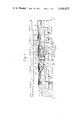
- FIG. 1 illustrates part of a record press embodying the invention
- FIG. 2 illustrates an enlarged portion of FIG. 1.
- the press illustrated in the drawing is particularly intended for the production of disc records of television signals by the impression of the contours of a matrix onto a thin sheet of thermoplastic material.
- the sheet may be elongate and be traversed between pressings so as to receive a series of impressions spaced apart along the sheet; subsequently the impressed regions may be trepanned from the sheet. It is alternatively possible to impress appropriately shaped pieces of sheet material separately.
- the press includes a thin conductive diaphragm 1 which is rigidly supported around its perimeter and which backs a thin conductive matrix 2 which on its front surface carries a negative of the physical contours that are to be impressed on the thermoplastic sheet.
- the sheet may be supported against the pressure of the diaphragm by a resilient cushion 3 or other means.
- the diaphragm 1 forms one broad wall of a narrow, substantially circular, pressure chamber 4, by which hydraulic pressure can be applied fluidly over the area of the diaphragm.
- the flexible diaphragm ensures that the matrix and the thermoplastic sheet, both flexible components, are centred horizontally between the compressing platens even though these may not be parallel and the matrix and the thermoplastic sheet may not be of constant thickness. It is desirable to produce impressions by a combination of pressure and heat and for this purpose heat can be transferred from the fluid in the pressure chamber through the thermally conductive diaphragm and matrix to the sheet of thermoplastic material which is disposed between the matrix 2 and the cushion 3. It is appropriate to provide a cycle of operation in which the inlet of relatively hot liquid is displaced by relatively cool liquid in preparation of the next pressing.
- the chamber 4 is bounded at its periphery by a wall 5 and its other broad wall is formed by an annular plate 6 which is connected at its inner periphery to a rubber securing ring 6a, which is in turn connected to a flange 7 of a flanged bush 8 having a central bore 9 communicating with the chamber 4 at the centre thereof.
- This bore provides a central outlet for liquid from the chamber 4.
- the perimeter gap between the plate 6 and the side wall 5 constitutes an annular inlet for liquid to the chamber 4 to facilitate the provision of a circumferentially symmetrical flow of liquid in the chamber.
- an antechamber 10 In communication with the chamber 4 by means of the perimeter gap 8 is an antechamber 10 which is generally annular.
- the antechamber 10 is bounded at its inner periphery by a sintered bronze collar 11 which is disposed between an annular portion 14 of a plate 12, which is spaced apart from and parallel to the plate 6, and a clamp ring 7a mounted on the flange 7.
- the bronze collar 11 fits closely around the flange 7 so as to provide the only means of entry into the antechamber from a substantially cylindrical inlet chamber 13 which is bounded by the bush 8, the collar 11, the flange 7, clamp ring 7a, a portion 12a of the plate 12 and a plate 13a.
- the other broad wall of the antechamber is principally constituted by a second annular portion 15 of plate 12 which is parallel to plate 6.
- the plate portion 15 constitutes the outer skin of a cellular structure 17 of which the internal walls 171 are disposed perpendicular to the general plane of the chambers 4 and 10.
- Inlet pipes 18 and 19 are provided for supplying hot and cold liquid (preferably oil) alternately to the inlet chamber 13 via a hole 16 in the plate 12.
- the plate 12 is formed with a frusto-conical baffle portion 16a which forces the incoming flow towards the bush 8 before it passes through the hole 16. The liquid flow is then forced through the collar, the antechamber l0 and the chamber 4 and out through the outlet bore 9.
- the purpose of the cellular structure 17 is to provide for the combined chamber constituted by the chamber 4 and the chamber 10, a wall which is of low thermal inertia and thereby assist rapid, alternate heating and cooling.
- At least the main pressure chamber 4 and in this embodiment both the chamber 4 and the chamber 10, are occupied by a multi-partite conductive structure denoted by 20 and 21 for the chamber 4 and the chamber 10 respectively.
- This structure provides sinuous paths for the liquid which traverses the chambers and helps to prevent laminar flow in the main chamber 4.
- the consequent increase of the length of travel of liquid across the chamber and the conductive nature of the structure both improve the transfer of heat between the liquid and the diaphragm.
- the flexible connection of the plate 6, which supports the structure 20, to the flange 7 via the rubber se curing ring 6a allows the plate 6 limited freedom of movement towards and away from the diaphragm so that an increase in the pressure gradient which causes flow of liquid through the chamber 4 raises the plate 6 to press the structure 20 against the diaphragm; this action improves the thermal connection between the diaphragm and the liquid.
- the depth of the chamber is adjusted automatically to that which just contains the structure.
- the sintered collar 11 provides a physical impedance to the flow of liquid into the pressure chamber from the inlet pipes.
- the inlet and outlet pipes are connected to appropriate hydraulic circuits preferably including a cold circuit chamber and appropriate valves for diverting hot and cold fluid to the nlet pipes.
- the circuits may be associated with a pressure intensifier which would normally be operated either immediately before or during the inlet of hot fluid to the pressure chamber.
- a record-making press comprising a narrow hydraulic pressure chamber of which one broad wall is constituted by a flexible thermally conductive diaphragm capable of impressing contours of a matrix onto a sheet of thermoplastic material, a hydraulic fluid inlet and hydraulic fluid outlet for the chamber, and a thermally conductive structure which extends throughout a substantial part of the chamber for inducing turbulence into the flow of fluid therethrough.
- thermally conductive structure is a multi partite conductive structure.
- thermoly conductive structure is a mesh.
Abstract
A record making press comprises a narrow hydraulic pressure chamber of which one broad wall is constituted by a flexible thermally conductive diaphragm capable of impressing contours of a matrix onto a sheet of thermoplastic material, a hydraulic fluid inlet and hydraulic fluid outlet for the chamber, and a thermally conductive structure which extends throughout a substantial part of the chamber for inducing turbulence into the flow of fluid therethrough.
Description
United States Patent Phillipson et al.
RECORD MAKING PRESS Inventors: Alan Phillipson; Basil Harry Royston Spiller; Cyril Leslie Newman; Robin Smith, all of London, England Assignee: Decca Limited, London, England Filed: Nov. 12, 1974 Appl. No.: 523,114
Foreign Application Priority Data Nov. 22, 1973 United Kingdom 54212/73 US. Cl. 425/384; 425/385; 425/810;
249/79 Int. Cl. B29C 17/00; B25D 17/00 Field of Search 425/384, 385, 810; 249/79 References Cited UNITED STATES PATENTS 9/1961 Renoux 425/810 X Nov. 11, 1975 3819.315 6/1974 Borchard et :11. 425/385 X 3,830,459 8/1974 Strausfeld 425/810 3860.382 l/l975 Spiller et a1 425/810 Primary E.\'uminer.l. Howard Flint, Jr. Almrney, Agem, 0r Firm-Edward F. Connors 5 Claims, 2 Drawing Figures Sheet 1 of 2 3,918,875
US. Patent Nov. 11, 1975 US. Patent Nov. 11, 1975 Sheet 2 of2 3,918,875
Q 9% Q 9Q Q RECORD MAKING PRESS This invention relates to a record making press which has a hydraulic pressure chamber for exerting pressure on a thin flexible conductive diaphragm in order to impress the contours of a matrix on a thin flexible thermoplastic sheet. Such a press is particularly, although not exclusively, intended for making disc records each bearing a physical representation of a television signal.
The main object of the invention is to facilitate the provision of a rapid cycle of operation of such a press.
According to the invention, there is provided a record-making press comprising a narrow hydraulic pressure chamber of which one broad wall is constituted by a flexible thermally conductive diaphragm capable of impressing contours of a matrix onto a sheet of thermoplastic material, a hydraulic fluid inlet and hydraulic fluid outlet for the chamber, and a thermally conductive structure which extends throughout a substantial part of the chamber for inducing turbulence into the flow of fluid therethrough.
The structure facilitates rapid transfer of heat between liquid in the chamber and the diaphragm.
Preferably the thermally conductive structure is a multi-partite structure, which may be a mesh. Means are preferably provided for supplying hot and cold hydraulic fluid alternately to the inlet of the chamber.
In a preferred embodiment, a second narrow hydraulic pressure chamber containing a thermally conductive structure as aforesaid for inducing turbulence into the flow is arranged adjacent and parallel to the first-mentioned chamber with the outlet of the second chamber in fluid communication with the inlet of the first chamber.
There follows a description of a record-making press incorporating one embodiment of the invention by way of example.
Reference will hereinafter be made to the accompanying drawings of which;
FIG. 1 illustrates part of a record press embodying the invention, and
FIG. 2 illustrates an enlarged portion of FIG. 1.
The press illustrated in the drawing is particularly intended for the production of disc records of television signals by the impression of the contours of a matrix onto a thin sheet of thermoplastic material. The sheet may be elongate and be traversed between pressings so as to receive a series of impressions spaced apart along the sheet; subsequently the impressed regions may be trepanned from the sheet. It is alternatively possible to impress appropriately shaped pieces of sheet material separately.
The press includes a thin conductive diaphragm 1 which is rigidly supported around its perimeter and which backs a thin conductive matrix 2 which on its front surface carries a negative of the physical contours that are to be impressed on the thermoplastic sheet. The sheet may be supported against the pressure of the diaphragm by a resilient cushion 3 or other means.
The diaphragm 1 forms one broad wall of a narrow, substantially circular, pressure chamber 4, by which hydraulic pressure can be applied fluidly over the area of the diaphragm. The flexible diaphragm ensures that the matrix and the thermoplastic sheet, both flexible components, are centred horizontally between the compressing platens even though these may not be parallel and the matrix and the thermoplastic sheet may not be of constant thickness. It is desirable to produce impressions by a combination of pressure and heat and for this purpose heat can be transferred from the fluid in the pressure chamber through the thermally conductive diaphragm and matrix to the sheet of thermoplastic material which is disposed between the matrix 2 and the cushion 3. It is appropriate to provide a cycle of operation in which the inlet of relatively hot liquid is displaced by relatively cool liquid in preparation of the next pressing.
The chamber 4 is bounded at its periphery by a wall 5 and its other broad wall is formed by an annular plate 6 which is connected at its inner periphery to a rubber securing ring 6a, which is in turn connected to a flange 7 of a flanged bush 8 having a central bore 9 communicating with the chamber 4 at the centre thereof. This bore provides a central outlet for liquid from the chamber 4. The perimeter gap between the plate 6 and the side wall 5 constitutes an annular inlet for liquid to the chamber 4 to facilitate the provision of a circumferentially symmetrical flow of liquid in the chamber.
In communication with the chamber 4 by means of the perimeter gap 8 is an antechamber 10 which is generally annular. The antechamber 10 is bounded at its inner periphery by a sintered bronze collar 11 which is disposed between an annular portion 14 of a plate 12, which is spaced apart from and parallel to the plate 6, and a clamp ring 7a mounted on the flange 7. The bronze collar 11 fits closely around the flange 7 so as to provide the only means of entry into the antechamber from a substantially cylindrical inlet chamber 13 which is bounded by the bush 8, the collar 11, the flange 7, clamp ring 7a, a portion 12a of the plate 12 and a plate 13a. The other broad wall of the antechamber is principally constituted by a second annular portion 15 of plate 12 which is parallel to plate 6. The plate portion 15 constitutes the outer skin of a cellular structure 17 of which the internal walls 171 are disposed perpendicular to the general plane of the chambers 4 and 10.
Inlet pipes 18 and 19 are provided for supplying hot and cold liquid (preferably oil) alternately to the inlet chamber 13 via a hole 16 in the plate 12. To inhibit nonuniformity of temperature in the liquid from either inlet pipe into the inlet chamber, the plate 12 is formed with a frusto-conical baffle portion 16a which forces the incoming flow towards the bush 8 before it passes through the hole 16. The liquid flow is then forced through the collar, the antechamber l0 and the chamber 4 and out through the outlet bore 9.
The purpose of the cellular structure 17 is to provide for the combined chamber constituted by the chamber 4 and the chamber 10, a wall which is of low thermal inertia and thereby assist rapid, alternate heating and cooling.
At least the main pressure chamber 4 and in this embodiment both the chamber 4 and the chamber 10, are occupied by a multi-partite conductive structure denoted by 20 and 21 for the chamber 4 and the chamber 10 respectively. This structure provides sinuous paths for the liquid which traverses the chambers and helps to prevent laminar flow in the main chamber 4. The consequent increase of the length of travel of liquid across the chamber and the conductive nature of the structure (which may be a mesh) both improve the transfer of heat between the liquid and the diaphragm.
The flexible connection of the plate 6, which supports the structure 20, to the flange 7 via the rubber se curing ring 6a allows the plate 6 limited freedom of movement towards and away from the diaphragm so that an increase in the pressure gradient which causes flow of liquid through the chamber 4 raises the plate 6 to press the structure 20 against the diaphragm; this action improves the thermal connection between the diaphragm and the liquid. Moreover, the depth of the chamber is adjusted automatically to that which just contains the structure.
The sintered collar 11 provides a physical impedance to the flow of liquid into the pressure chamber from the inlet pipes. By this means non-uniformities in the distribution of fluid to the inlet chamber are very largely vitiated so that liquid flows in the chambers 4 and substantially radially and uniformly, that is to say circumferentially invariantly.
The inlet and outlet pipes are connected to appropriate hydraulic circuits preferably including a cold circuit chamber and appropriate valves for diverting hot and cold fluid to the nlet pipes. The circuits may be associated with a pressure intensifier which would normally be operated either immediately before or during the inlet of hot fluid to the pressure chamber.
We claim:
1. A record-making press comprising a narrow hydraulic pressure chamber of which one broad wall is constituted by a flexible thermally conductive diaphragm capable of impressing contours of a matrix onto a sheet of thermoplastic material, a hydraulic fluid inlet and hydraulic fluid outlet for the chamber, and a thermally conductive structure which extends throughout a substantial part of the chamber for inducing turbulence into the flow of fluid therethrough.
2. A record-making press as claimed in claim 1, in which the thermally conductive structure is a multi partite conductive structure.
3. A record-making press as claimed in claim 1, in which the thermally conductive structure is a mesh.
4. A record-making press as claimed in claim 1, in which means are provided for supplying hot and cold hydraulic fluid alternately to the inlet of the chamber.
5. A record-making press as claimed in claim 1, in which a second narrow hydraulic pressure chamber containing a thermally conductive structure as aforesaid for inducing turbulence into the flow is arranged adjacent and parallel to the first-mentioned chamber with the outlet of the second chamber in fluid communication with the inlet of the first chamber.
=l l l l =l
Claims (5)
1. A record-making press comprising a narrow hydraulic pressure chamber of which one broad wall is constituted by a flexible thermally conductive diaphragm capable of impressing contours of a matrix onto a sheet of thermoplastic material, a hydraulic fluid inlet and hydraulic fluid outlet for the chamber, and a thermally conductive structure which extends throughout a substantial part of the chamber for inducing turbulence into the flow of fluid therethrough.
2. A record-making press as claimed in claim 1, in which the thermally conductive structure is a multi-partite conductive structure.
3. A record-making press as claimed in claim 1, in which the thermally conductive structure is a mesh.
4. A record-making press as claimed in claim 1, in which means are provided for supplying hot and cold hydraulic fluid alternately to the inlet of the chamber.
5. A record-making press as claimed in claim 1, in which a second narrow hydraulic pressure chamber containing a thermally conductive structure as aforesaid for inducing turbulence into the flow is arranged adjacent and parallel to the first-mentioned chamber with the outlet of the second chamber in fluid communication with the inlet of the first chamber.
Applications Claiming Priority (1)
| Application Number | Priority Date | Filing Date | Title |
|---|---|---|---|
| GB54212/73A GB1484257A (en) | 1973-11-22 | 1973-11-22 | Record-making press |
Publications (1)
| Publication Number | Publication Date |
|---|---|
| US3918875A true US3918875A (en) | 1975-11-11 |
Family
ID=10470296
Family Applications (1)
| Application Number | Title | Priority Date | Filing Date |
|---|---|---|---|
| US523114A Expired - Lifetime US3918875A (en) | 1973-11-22 | 1974-11-12 | Record making press |
Country Status (14)
| Country | Link |
|---|---|
| US (1) | US3918875A (en) |
| JP (1) | JPS5714967B2 (en) |
| AT (1) | AT347146B (en) |
| BE (1) | BE822469A (en) |
| CA (1) | CA1028458A (en) |
| CH (1) | CH581021A5 (en) |
| DE (1) | DE2455224A1 (en) |
| DK (1) | DK140521B (en) |
| FR (1) | FR2252199B1 (en) |
| GB (1) | GB1484257A (en) |
| IT (1) | IT1024890B (en) |
| NL (1) | NL164795C (en) |
| NO (1) | NO142056C (en) |
| SE (1) | SE410833B (en) |
Cited By (15)
| Publication number | Priority date | Publication date | Assignee | Title |
|---|---|---|---|---|
| US4018552A (en) * | 1974-11-27 | 1977-04-19 | U.S. Philips Corporation | Pressing block for die pressing thermoplastic material |
| US4141531A (en) * | 1976-02-29 | 1979-02-27 | Emi Electrola Gesellschaft Mit Beschrankter Haftung | Disc record press |
| US4219321A (en) * | 1978-12-21 | 1980-08-26 | U.S. Philips Corporation | Device for making discs |
| US4231730A (en) * | 1978-11-25 | 1980-11-04 | E M I Limited | Moulding video discs |
| US4245811A (en) * | 1978-06-06 | 1981-01-20 | Messerschmitt-Bolkow-Blohm Gesellschaft Mit Beschrankter Haftung | Press mould half, more especially for producing records |
| US4315723A (en) * | 1979-09-06 | 1982-02-16 | Thomson-Csf | Device for molding information-carrying disks |
| US4364720A (en) * | 1980-12-22 | 1982-12-21 | Ryder International Corporation | Molding machine and system for accomodating a plurality of such machines |
| US4397627A (en) * | 1982-03-18 | 1983-08-09 | Rca Corporation | Apparatus for molding a recorded disc |
| US4612081A (en) * | 1984-08-13 | 1986-09-16 | Maschinenfabrik J. Dieffenbacher Gmbh & Co. | Pressure equalizing pad for heated plate presses |
| US5316464A (en) * | 1992-12-16 | 1994-05-31 | Lexell Jason R | Compact disc labeling system |
| US5855933A (en) * | 1992-10-16 | 1999-01-05 | Innova Zug Ag | Temperature-controllable tool or mold for producing plastic moldings and process for making such tools or molds |
| EP1362682A1 (en) * | 2002-05-13 | 2003-11-19 | ZBD Displays Ltd, | Method and apparatus for liquid crystal alignment |
| US20050236738A1 (en) * | 2002-09-12 | 2005-10-27 | Harper Bruce M | Disk alignment apparatus and method for patterned media production |
| US20060286190A1 (en) * | 2005-06-17 | 2006-12-21 | Owens-Illinois Closure, Inc. | Molding machine |
| EP2388120A3 (en) * | 2010-05-22 | 2014-10-01 | Linter Spolka z ograniczona odpowiedzialnoscia | Heating press plate of vulcanizing press machine, unit of heating press plates and vulcanization method using heating press plates |
Families Citing this family (1)
| Publication number | Priority date | Publication date | Assignee | Title |
|---|---|---|---|---|
| JPS62134349U (en) * | 1986-02-19 | 1987-08-24 |
Citations (4)
| Publication number | Priority date | Publication date | Assignee | Title |
|---|---|---|---|---|
| US2998622A (en) * | 1957-12-23 | 1961-09-05 | Applic Ind Plastiques Soc D | Apparatus for pressing gramophone records |
| US3819315A (en) * | 1973-01-09 | 1974-06-25 | Ted Bildplatten | Apparatus for stamping information carriers from a plastic foil |
| US3830459A (en) * | 1972-06-28 | 1974-08-20 | Emi Electrola Gmbh | Record presses |
| US3860382A (en) * | 1972-02-23 | 1975-01-14 | Decca Ltd | Apparatus for the manufacture of contoured records |
-
1973
- 1973-11-22 GB GB54212/73A patent/GB1484257A/en not_active Expired
-
1974
- 1974-11-12 US US523114A patent/US3918875A/en not_active Expired - Lifetime
- 1974-11-18 NO NO744136A patent/NO142056C/en unknown
- 1974-11-20 CH CH1545474A patent/CH581021A5/xx not_active IP Right Cessation
- 1974-11-21 BE BE150743A patent/BE822469A/en unknown
- 1974-11-21 CA CA214,381A patent/CA1028458A/en not_active Expired
- 1974-11-21 FR FR7438238A patent/FR2252199B1/fr not_active Expired
- 1974-11-21 AT AT936174A patent/AT347146B/en not_active IP Right Cessation
- 1974-11-21 JP JP13320674A patent/JPS5714967B2/ja not_active Expired
- 1974-11-21 DK DK607574AA patent/DK140521B/en unknown
- 1974-11-21 SE SE7414637A patent/SE410833B/en unknown
- 1974-11-21 IT IT70413/74A patent/IT1024890B/en active
- 1974-11-21 DE DE19742455224 patent/DE2455224A1/en not_active Ceased
- 1974-11-21 NL NL7415192.A patent/NL164795C/en active
Patent Citations (4)
| Publication number | Priority date | Publication date | Assignee | Title |
|---|---|---|---|---|
| US2998622A (en) * | 1957-12-23 | 1961-09-05 | Applic Ind Plastiques Soc D | Apparatus for pressing gramophone records |
| US3860382A (en) * | 1972-02-23 | 1975-01-14 | Decca Ltd | Apparatus for the manufacture of contoured records |
| US3830459A (en) * | 1972-06-28 | 1974-08-20 | Emi Electrola Gmbh | Record presses |
| US3819315A (en) * | 1973-01-09 | 1974-06-25 | Ted Bildplatten | Apparatus for stamping information carriers from a plastic foil |
Cited By (24)
| Publication number | Priority date | Publication date | Assignee | Title |
|---|---|---|---|---|
| US4018552A (en) * | 1974-11-27 | 1977-04-19 | U.S. Philips Corporation | Pressing block for die pressing thermoplastic material |
| US4141531A (en) * | 1976-02-29 | 1979-02-27 | Emi Electrola Gesellschaft Mit Beschrankter Haftung | Disc record press |
| US4245811A (en) * | 1978-06-06 | 1981-01-20 | Messerschmitt-Bolkow-Blohm Gesellschaft Mit Beschrankter Haftung | Press mould half, more especially for producing records |
| US4231730A (en) * | 1978-11-25 | 1980-11-04 | E M I Limited | Moulding video discs |
| US4219321A (en) * | 1978-12-21 | 1980-08-26 | U.S. Philips Corporation | Device for making discs |
| US4315723A (en) * | 1979-09-06 | 1982-02-16 | Thomson-Csf | Device for molding information-carrying disks |
| US4364720A (en) * | 1980-12-22 | 1982-12-21 | Ryder International Corporation | Molding machine and system for accomodating a plurality of such machines |
| US4397627A (en) * | 1982-03-18 | 1983-08-09 | Rca Corporation | Apparatus for molding a recorded disc |
| US4612081A (en) * | 1984-08-13 | 1986-09-16 | Maschinenfabrik J. Dieffenbacher Gmbh & Co. | Pressure equalizing pad for heated plate presses |
| US5855933A (en) * | 1992-10-16 | 1999-01-05 | Innova Zug Ag | Temperature-controllable tool or mold for producing plastic moldings and process for making such tools or molds |
| US5316464A (en) * | 1992-12-16 | 1994-05-31 | Lexell Jason R | Compact disc labeling system |
| WO2003095175A2 (en) * | 2002-05-13 | 2003-11-20 | Zbd Displays Ltd | Embossing method and apparatus |
| EP1362682A1 (en) * | 2002-05-13 | 2003-11-19 | ZBD Displays Ltd, | Method and apparatus for liquid crystal alignment |
| WO2003095175A3 (en) * | 2002-05-13 | 2004-02-19 | Zbd Displays Ltd | Embossing method and apparatus |
| US20050150589A1 (en) * | 2002-05-13 | 2005-07-14 | Amos Richard M. | Embossing method and apparatus |
| US7824516B2 (en) | 2002-05-13 | 2010-11-02 | Zbd Displays Limited | Embossing method and apparatus |
| US20050236738A1 (en) * | 2002-09-12 | 2005-10-27 | Harper Bruce M | Disk alignment apparatus and method for patterned media production |
| US7682546B2 (en) * | 2002-09-12 | 2010-03-23 | Wd Media, Inc. | Disk alignment apparatus and method for patterned media production |
| US20060286190A1 (en) * | 2005-06-17 | 2006-12-21 | Owens-Illinois Closure, Inc. | Molding machine |
| US7431582B2 (en) | 2005-06-17 | 2008-10-07 | Rexam Closure Systems Inc. | Molding machine |
| US20080303183A1 (en) * | 2005-06-17 | 2008-12-11 | Rote B Jack | Molding machine |
| US7934920B2 (en) | 2005-06-17 | 2011-05-03 | Rexam Closure Systems Inc. | Molding machine |
| US8469695B2 (en) | 2005-06-17 | 2013-06-25 | Berry Plastics Corporation | Molding machine |
| EP2388120A3 (en) * | 2010-05-22 | 2014-10-01 | Linter Spolka z ograniczona odpowiedzialnoscia | Heating press plate of vulcanizing press machine, unit of heating press plates and vulcanization method using heating press plates |
Also Published As
| Publication number | Publication date |
|---|---|
| NL164795B (en) | 1980-09-15 |
| NO142056B (en) | 1980-03-10 |
| NL164795C (en) | 1981-02-16 |
| IT1024890B (en) | 1978-07-20 |
| DK140521B (en) | 1979-09-24 |
| FR2252199A1 (en) | 1975-06-20 |
| SE7414637L (en) | 1975-05-23 |
| DK607574A (en) | 1975-07-14 |
| CA1028458A (en) | 1978-03-28 |
| AU7531774A (en) | 1976-05-13 |
| BE822469A (en) | 1975-03-14 |
| GB1484257A (en) | 1977-09-01 |
| NO142056C (en) | 1980-06-18 |
| SE410833B (en) | 1979-11-12 |
| FR2252199B1 (en) | 1977-03-25 |
| ATA936174A (en) | 1978-04-15 |
| DK140521C (en) | 1980-02-18 |
| NL7415192A (en) | 1975-05-26 |
| CH581021A5 (en) | 1976-10-29 |
| DE2455224A1 (en) | 1975-05-28 |
| AT347146B (en) | 1978-12-11 |
| JPS50106602A (en) | 1975-08-22 |
| NO744136L (en) | 1975-06-16 |
| JPS5714967B2 (en) | 1982-03-27 |
Similar Documents
| Publication | Publication Date | Title |
|---|---|---|
| US3918875A (en) | Record making press | |
| JP2965908B2 (en) | Mold device for optical disk molding provided with temperature-controlled liquid sealing means | |
| CA2682907A1 (en) | Metal plate material hot press molding apparatus and hot press molding method | |
| US3830459A (en) | Record presses | |
| US3474494A (en) | Gramophone record presses | |
| GB956422A (en) | Improvements in or relating to heatable processes | |
| US3427687A (en) | Mold construction | |
| GB1348410A (en) | Extrusion dies | |
| US2435170A (en) | Apparatus for molding plastic articles | |
| US2290917A (en) | Lens molding press | |
| US3031960A (en) | Method of manufacturing electrotype plates | |
| US3209058A (en) | High temperature rotor | |
| US2156396A (en) | Extrusion mold | |
| US2715752A (en) | Apparatus for the manufacture of phonograph records | |
| JPH05278088A (en) | Mold for molding optical disc | |
| GB1205623A (en) | Improvements in or relating to a method and apparatus for the manufacture of gramophone records | |
| JPH0270407A (en) | Molding die | |
| GB923958A (en) | Improvements in and relating to presses for hot working of a metal billet within a container | |
| JPS6382714A (en) | Molding tool for disk base | |
| US2203787A (en) | Molding means for making thermoplastic articles | |
| CN116887531B (en) | Method for implementing temperature control hot-press shaping on sealing glue PCB substrate | |
| JPS60174619A (en) | Pressure mold | |
| JP2001097726A (en) | Mold for molding optical material | |
| JPS59145109A (en) | Molding process for rotating plate of heat cooking instrument | |
| GB2037651A (en) | Apparatus for pressing record discs |