US3911645A - Folding device for packaging material - Google Patents
Folding device for packaging material Download PDFInfo
- Publication number
- US3911645A US3911645A US422484A US42248473A US3911645A US 3911645 A US3911645 A US 3911645A US 422484 A US422484 A US 422484A US 42248473 A US42248473 A US 42248473A US 3911645 A US3911645 A US 3911645A
- Authority
- US
- United States
- Prior art keywords
- cell
- station
- article
- folder member
- sheet
- Prior art date
- Legal status (The legal status is an assumption and is not a legal conclusion. Google has not performed a legal analysis and makes no representation as to the accuracy of the status listed.)
- Expired - Lifetime
Links
- 239000005022 packaging material Substances 0.000 title description 13
- 239000000463 material Substances 0.000 claims abstract description 36
- 230000008878 coupling Effects 0.000 claims description 12
- 238000010168 coupling process Methods 0.000 claims description 12
- 238000005859 coupling reaction Methods 0.000 claims description 12
- 230000000977 initiatory effect Effects 0.000 abstract description 3
- 235000019504 cigarettes Nutrition 0.000 description 20
- 238000003780 insertion Methods 0.000 description 4
- 230000037431 insertion Effects 0.000 description 4
- 238000004806 packaging method and process Methods 0.000 description 4
- 239000000853 adhesive Substances 0.000 description 3
- 230000001070 adhesive effect Effects 0.000 description 3
- 238000010276 construction Methods 0.000 description 3
- 229920000297 Rayon Polymers 0.000 description 2
- ATJFFYVFTNAWJD-UHFFFAOYSA-N Tin Chemical compound [Sn] ATJFFYVFTNAWJD-UHFFFAOYSA-N 0.000 description 2
- 230000008901 benefit Effects 0.000 description 2
- 229920002678 cellulose Polymers 0.000 description 2
- 239000001913 cellulose Substances 0.000 description 2
- 230000009977 dual effect Effects 0.000 description 2
- 241001673391 Entandrophragma candollei Species 0.000 description 1
- 239000005030 aluminium foil Substances 0.000 description 1
- 238000013459 approach Methods 0.000 description 1
- 239000003795 chemical substances by application Substances 0.000 description 1
- 230000006872 improvement Effects 0.000 description 1
- 229910052751 metal Inorganic materials 0.000 description 1
- 239000002184 metal Substances 0.000 description 1
- 238000000034 method Methods 0.000 description 1
- 230000004048 modification Effects 0.000 description 1
- 238000012986 modification Methods 0.000 description 1
- 230000008569 process Effects 0.000 description 1
- 238000007789 sealing Methods 0.000 description 1
- 229910052718 tin Inorganic materials 0.000 description 1
Images
Classifications
-
- B—PERFORMING OPERATIONS; TRANSPORTING
- B65—CONVEYING; PACKING; STORING; HANDLING THIN OR FILAMENTARY MATERIAL
- B65B—MACHINES, APPARATUS OR DEVICES FOR, OR METHODS OF, PACKAGING ARTICLES OR MATERIALS; UNPACKING
- B65B19/00—Packaging rod-shaped or tubular articles susceptible to damage by abrasion or pressure, e.g. cigarettes, cigars, macaroni, spaghetti, drinking straws or welding electrodes
- B65B19/02—Packaging cigarettes
- B65B19/22—Wrapping the cigarettes; Packaging the cigarettes in containers formed by folding wrapping material around formers
- B65B19/223—Wrapping the cigarettes; Packaging the cigarettes in containers formed by folding wrapping material around formers in a curved path; in a combination of straight and curved paths, e.g. on rotary tables or other endless conveyors
Definitions
- the device comprises a revolver provided with wall members defining a plurality of cells, the revolver being so rotatable stepwise that each of the cells comes to rest successively at a first station, a second station, a third station and a fourth station of the device.
- the cells are constructed so to receive at the first station a sheet of wrapping material and so to receive at the second station an article to be wrapped that such sheet of wrapping material is disposed between ,the received article and walls of the cell in which that article is received, with lobes of the sheet projecting in a direction radial to the axis of rotation beyond a radially outward facing side of the article.
- Folder means are disposed at the second station, the folder means comprising a folder member rotatably mounted 'on carrier means reciprocatably displaceable along guide means, and drive means to displace the folder member between a first position in which the folder member is radially spaced apart from the radially outward facing side of a cell at the second station and a second position in which the folder member is disposed next adjacent the radially outward facing side of the cell at the second station.
- the drive means in displacing the folder member from its first position towardsits second position, initially imparts rotational motion to the folder member relative to the carrier means and, subsequently to the initiation of the rotational motion, imparts such translational motion to the carrier means that when the device is in use the folder member is moved along the radially outward facing side of the cell at the second station to engage one of the radially projecting lobes and to fold the latter against that side of an article in the cell.
- the present invention relates to a device for folding individual sheets of wrapping material around portions of the external surfaces of successive articles of parallelepipedonal shape.
- a device for folding a sheet of wrapping material around external surfaces of an article of parallelepipedonal shape comprising a revolver provided with wall members defining a plurality of cells, the revolver being so rotatable stepwise that each of the cells comes to rest successively at a first station, a second station, a third station and a fourth station of the device, the cells being constructed so to receive at the first station a sheet of wrapping material and so to receive at the second station an article to be wrapped that such sheet of wrapping material is disposed between the received article and walls of the cell in which that article is received, with lobes of the sheet projecting in a direction radial to the axis of rotation beyond a radially outward facing side of the article, folder means disposed at the second station, the folder means comprising a folder member rotatably mounted on carrier means reciprocatably displaceable along guide means, and drive means to displace the folder member between a first position in which the
- a folding means incorporating a folding element which executes both rotary and translational motion is a particularly convenient form of folding means to be provided at the second station of the folding device,
- such a folding means preferably being employed to fold the trailing projecting lobe of packaging material, ie the lobe which is at the rear of the package as far as the direction of motion of the package about the axis of rotation is concerned.
- the folding, in the opposite sense, of the leading lobe of packaging material may conveniently take place by means of a stationary folding element, while the cell executes its step of rotation from the second station to the third station.
- the folding means may thus include the end surface of a stationary folding element, for example of sheet metal, past which a cell moves just after commencing its motion from the position at the second station in which thecell comes to rest.
- the folding member which executes both rotary and translational motion preferably acts on the trailing lobe when the revolver is stationary.
- U.S. patent application Ser. No. 419,467 now U.S. Pat. No. 3,857,221 discloses a folding arrangement to be used at the third station of a packaging machine of the kind disclosed in U.S. patent application Ser. No. 403,732, that folding arrangement including folding means incorporating a folding member which executes both rotary and translational motion.
- the present folding element differs from that disclosed in U.S. patent application Ser. No. 419,467, in that in the present case nearly all, if not completely all, of the rotational motion of the folding element, which takes place in passing from the first position of the folding element to the second position, takes place before the translational motion.
- a common plate member is provided in the folding device to act as a support mounting for a set of guide rods which guide a carriage on which the folding element is mounted and or a housing having a rotatable shaft passing therethrough and carrying cams forming part of the drive means.
- the guide rods prefferably be of linear construction and thus to guide the carriage to be reciprocable along a linear path, mounting means which carry the folding element being rotatably mounted on the carriage in such a manner that the cams control both the rotational motion and the translational motion of the folding element.
- a convenient construction is one in which the housing is provided with rocker shaft means passing therethrough, and mounted in roller or friction bearings, the rocker shaft means carrying a pair of levers having rollers mounted thereon to constitute cam followers cooperable with the earns, the rocker shaft means also carrying a further lever articulated to a connecting rod which is also articulated to the mounting means, coupling means being provided to couple the rocker shaft with the carriage.
- the guide rods extend vertically, and the carriage is reciprocable vertically.
- the arrangement is such that the folding element, in passing from its first position to its second position, executes initially a pivotal movement relative to the carriage under the control of the connecting rod, followed by a translational movement to bring the folding element into contact with the trailing projecting lobe of packaging material, the translational movement being under the control of the coupling means.
- the coupling means may comprise a lever member articulated to the carriage at one end and coupled to the rocker shaft at the other end.
- the rollers may be provided in twos, in such a manner that two rollers are mounted on each of the levers provided with rollers, each individual roller being arranged to follow the contour of a respective one of the cams.
- a packaging machine may be constructed, which comprises two of the above defined folding devices, one being provided to act on a U-shaped web of packaging material intended eventually to form an inner one of two wrappers, for example of viscose or cellulose film, around a cigarette block, and the other being arranged to act on a further web of packaging material intended to form the outer one of such two wrappers.
- individual revolvers are, of course, provided for the application of the two respective wrappers.
- the rocker shaft means may comprise a central shaft portion and a tubular shaft portion fitted on the central shaft portion, the levers being rigidly carried by the tubular shaft portion.
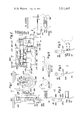
- FIG. I shows a front elevation, partly in section, of a folding device embodying the invention
- FIG. 2 shows a side elevational view of the embodiment shown in FIG. 1;
- FIG. 3 shows a detail, from the front, of a folding element and a cell of the revolver, in two different positions of the folding element
- FIG. 4 shows a similar detail to FIG. 3, in a different position of the folding element
- FIG. 5 shows a similar detail to FIG. 3 after a 5 anticlockwise movement of the revolver has taken place
- FIG. 6 shows schematically the various folds to be applied to a web of wrapping material.
- numeral 453 denotes a carriage slidable up and down on a plurality of vertical guide rods 454.
- a folding element 451 is carried by an arm 452 attached to mounting means in the form of a lever member 68 articulated to the carriage and rigid with a further lever 459 (FIG. 2) which carries a roller 484 which runs in a guideway defined between a pair of flanges 461 on a lever member 460.
- the guide rods 454 are carried by a support having a top member 455, a bottom member 456 and side wall members 481. The support is carried rigidly by and abuts against the lower surface of a plate member 77.
- the plate member 77 also carries rigidly by its lower surface, spaced a short distance from the support, a housing 479, 474 which carries a cam arrangement for driving the carriage for its up and down reciprocating movement.
- a shaft 465 passes through the housing 479, and is provided with a coupling element 471 at one end to coupled with a drive to rotate the shaft 465.
- Mounted on the shaft 465 at intervals are double cams 482 and 483 arranged in pairs as shown in FIG. 2, and a further shaft assembly in the form of rocker shaft means is shown above the shaft 465.
- the rocker shaft means comprises a central shaft portion 466 surrounded by a tubular shaft portion 467, the shaft portions 466 and 467 being rotatable relative to one another.
- a double armed lever 469 in the form of a bell crank is spaced from the lever 468, rigid with the portion 466 of the rocker shaft means, and carries a pair of rollers similar to the rollers 470 on opposite sides of the lever 469, and these rollers each separately engage one of the cams 482.
- Reference numeral 474 (FIG. 2) indicates a bottom portion of the housing 479, 474.
- Bearing members 475, 477 and 478, as well as roller or friction bearings 472, 473 and 476 are provided for mounting the shaft 465 and the rocker shaft means consisting of the portions 466 and 467 in the housing 479, 474.
- Closure plugs and sealing devices, as well as distance rings, Seeger rings, wedge members and other suitable fixing arrangements may be provided as required.
- connection is made between the support 455, 456, 481 and the housing 479, 474 by a lever 458 articulated to a thrust rod 457 (FIG. 2) carried by the carriage 453, the lever 458 being carried at the other end by the further shaft. and such connection is also made by a lever 464 articulated at its lefthand end (FIG. 1) either to the member 68 or to another member connected thereto, the lever 464 being articulated at its right-hand end (FIG. 1) to a lever 480 which, in similar manner to the levers 468 and 469, is carried by the rocker shaft means.
- the further shaft 466, 467 while being rotatable in the housing 479, 474 has no drive directly applied thereto from outside.
- An opening 482 is provided through the wall of the housing 479, 474 to enable the lever 458 to pass through the housing wall.
- the dual cam operated lever 468 drives the lever 464 in a reciprocating manner via the tubular shaft portion 467 and the connecting lever 480, while the lever 458 is driven in an oscillating manner by the dual cam operated lever 469 via the central shaft portion 466.
- the letter H indicates the distance through which the carriage 453 moves up and down in operationof the device.
- FIG. 1 also shows a cell of a four-cell revolver, the cell being carried by a mounting plate 213 of the revolver indicated generally at 351.
- a holder for the cell is shown at 324/325.
- the revolver may form part of a packaging machine of the kind disclosed in US. patent application Ser. No. 403,732.
- the revolver comprises rotatably supported article receiving means and cell defining means provided by wall members of the article receiving means to define a plurality of parallelepipedonal shaped cells spaced at angular intervals about the axis of rotation of the article receiving means and each extending in a generally radial direction relative to the axis. As indicated in the drawings, each cell has a radially outward facing opening.
- each opening extending substantially perpendicularly to the generally radial direction of the cells.
- Each cell is adapted to receive one parallelepipedonal shaped article.
- FIG. 1 two positions of the folding element 451 are shown, one in solid lines at 451a. which represents the first position of the folding element, i.e. that in which it is retracted out of the path of a projecting lobe of wrapper material extending radially outwardly of the revolver from a cell approaching the second station (the station shown in FIG. 1).
- the position of the folding element shown in dotted lines represents that adopted by the folding element after folding a trailing lobe of wrapping material, i.e. the upper lobe in FIG. 1, against the portion of the surface of a cigarette block in the cell beyond which both the leading and trailing lobes project prior to folding.
- FIG. 3 the trailing lobe is shown at 64g, and the leading lobe at 64/1.
- the wrapping material shown in FIG. 3 is an outer wrapper, characterised by the numeral 64.
- the numeral 63 in FIG. 2 indicates that a similar revolver may also be used in connection with a sheet of inner wrapper material for an American type of cigarette block.
- FIG. 3 there is also shown part of a stationary folding member 62, which acts to fold over, in the opposite sense to the trailing lobe, the leading lobe, in manner to be described more fully later.
- FIG. 3 shows the folding element 451 in broken lines in the first position at 451a, and in solid lines in an intermediate position 45lb.
- FIG. 4 shows the same folding element 451 in the second position at 451e, in which the folding element retains the upper or trailing lobe of the packaging material against the left-hand external surface portion of the cigarette block shown schematically only as representing five cigarettes. In practice of course, the entire cell is full of cigarettes to form a block.
- each cell of the revolver receives a U-shaped web of packaging material either with two equally long lobes projecting in a direction radial of the axis of rotation of the revolver (particularly convenient in the case of an inner wrapper sheet) or with the leading lobe longer than the trailing lobe (particularly convenient in the case of an outer wrapper sheet).
- the folding element 451 may be moved from position 45111 to position 451b and then to position 4510 to fold the trailing lobe over, which would, of course, be impossible if the cigarette block were not present at all in the cellv It is, however, convenient to carry out this fold while the block is only half introduced into the cell, and thus while the block is held together in a cell of a preceding revolver or in a feeding mouthpiece.
- the presence of the folding element 451 does of course contribute to the holding together of the cigarette block.
- the completion of the introduction of the cigarette block into the cell now takes place, and
- FIG. 5 shows the cell having advanced through 5 anti-clockwise from the second station shown in FIGS. 1, 3 and 4, from which it is clearly seen that the folding of the leading lobe of packaging material has almost been completed. This is, of course, completed before the cell arrives at the third station of the device.
- the folding element 451 and the sliding carriage 453 are at all times under the control of the cams carried by the rotating shaft 465.
- the cams are arranged to drive the folding element 451 in such a manner that initially it pivots relatively to the sliding carriage under the influence of the lever 464, and then it subsequently drops downwardly in FIG. 1 as a result of the entire carriage 453 being moved downwardly relatively to the guide rods 454 under. the influence of the lever 458.
- FIG. 2 On the right in FIG. 2 there are shown a leading lobe 63m and a trailing lobe 63k of inner wrapping material, of equal length in a direction radial of the axis of rotation of the revolver, and a leading lobe 64/1 and a trailing lobe 64g of outer wrapper material, of unequal length.
- This combined representation in FIG. 2 merely indicates that the described folding device may be used with either inner wrapper material or outer wrapper material.
- Either inner or outer wrapper material may for example consist of viscose or cellulose film, and the inner wrapper material may, if desired, be tin foil or aluminium foil.
- FIG. 6 shows diagrammatically the folding scheme followed in operation of the above described folding device, the trailing lobe projecting in the direction radial of the axis of rotation of the revolver being shown at 63k-1 in broken lines in its unfolded condition and at 63k-2 in solid lines in its condition as folded over by the folding element 451.
- the trailing lobe may be provided with a strip of adhesive, for example by means of the nozzle shown in the drawing of U.S. patent application Ser. No. 410,158. In this manner. securing of the two folded lobes may readily be accomplished. This is of particular advantage in the case of an outer wrapper. It may be preferred that an inner wrapper should not be provided with adhesive.
- revolver part of which is shown in the various Figures, may form either revolver II or revolver ll] of US. patent application Ser. No. 403,732.
- the above described initial half insertion of the cigarette block into the cell at the second station of the device may offer the following facilities;
- the cavity of the cell is about half filled and the folding element 451 can occupy the position 451C,
- the cigarette block is held together all the time during the process of insertion into the cell, either in the previous revolver from which the cigarette block is being supplied or in a mouthpiece component, and also in the above described cell at the second station of the device.
- a device for folding a sheet of wrapping material around external surfaces of an article of parallelepipedonal shape comprising, in combination:
- article receiving means rotatably mounted on said support to be rotatable about an axis
- each cell defining means provided by wall members of said article receiving means to define a plurality of parallelepipedonal shaped cells spaced at angular intervals about said axis and extending in a generally radial direction relative thereto, each cell having a radially outward facing opening each extending substantially perpendicularly to said generally radial direction, and each cell being adapted to re ceive one said article:
- first drive means to rotate said article receiving means stepwise about said axis to cause each said cell to be arrested successively at a first station where a sheet of wrapping material is introduced into one said cell, a second station where said article is introduced axially into said cell such that said sheet of wrapping material is disposed between said article and walls of said cell in which said article is received, with lobes of said sheet projecting beyond the said opening and in a direction generally radial to said axis, a third station and a fourth station of said device;
- carrier means mounted to be reciprocatably displaceable along said guide means; a folder member rotatably supported on said carrier means; and second drive means to displace said folder member between a first position in which said folder member is radially spaced apart from said opening of said cell at said second station and a second position in which said folder member is disposed next adjacent said opening of said cell of said second station said second drive means, in displacing said folder member from said first position towards said second position, initially imparting rotational motion to said folder member relative to said carrier means and, subsequently to said rotational motion, imparting translational motion to said carrier means, said translational motion being initiated only after said article has been partially introduced axially into said cell and before said article has been completely introduced therein; whereby said folder member is moved along said opening of said cell at said second station to engage one of said radially projecting lobes and to fold said one lobe against the radially outer side face of said article substantially contemporaneously with the introduction of said article into said cell.
- a device for folding a sheet of wrapper material around external surfaces of an article of parallelepipedonal shape comprising, in combination:
- article receiving means rotatably mounted on said support to be rotatable about an axis; cell defining means provided by wall members of said article receiving means to define a plurality of parallelepipedonal shaped cells spaced at angular intervals about said axis and extending in a generally radial direction relative thereto, each cell having a radially outward facing opening each extending substantially perpendicularly to said generally radial direction, and each cell being adapted to receive one said article;
- first drive means to' rotate said article receiving means stepwise about said axis to causeeach said cell to be arrested successively at a first station where a sheet of wrapping material is introduced into one said cell, a second station where said article is introduced into said cell such that said sheet of wrapping material is disposed between said article and walls of said cell in which said article is received, with lobes of said sheet projecting beyond the said opening and in a direction generally radial to said axis, a third station and a fourth station of said device;
- carrier means mounted to be reciprocatably displaceable along said guide means
- second drive means comprising a rotatably mounted shaft, a plurality of cams mounted on said shaft to rotate therewith, rocker shaft means extending parallel to said first mentioned shaft and provided with cam follower means to engage said cams on said first shaft, first coupling means coupling said folder member to said rocker shaft means, and second coupling means coupling said carrier means to said rocker shaft means, said second drive means being to said folder member relative to said carrier means and, subsequently to said rotational motion, imparting translational motion to said carrier means; whereby said folder member is moved along said opening of said cell at said second station to engage one of said radially projecting lobes and to fold said one lobe againstthe radially outer side face of said article in said cell.
Landscapes
- Engineering & Computer Science (AREA)
- Mechanical Engineering (AREA)
- Wrapping Of Specific Fragile Articles (AREA)
- Basic Packing Technique (AREA)
Abstract
A device for folding a sheet of wrapping material around external surfaces of an article of parallelepipedonal shape is disclosed. The device comprises a revolver provided with wall members defining a plurality of cells, the revolver being so rotatable stepwise that each of the cells comes to rest successively at a first station, a second station, a third station and a fourth station of the device. The cells are constructed so to receive at the first station a sheet of wrapping material and so to receive at the second station an article to be wrapped that such sheet of wrapping material is disposed between the received article and walls of the cell in which that article is received, with lobes of the sheet projecting in a direction radial to the axis of rotation beyond a radially outward facing side of the article. Folder means are disposed at the second station, the folder means comprising a folder member rotatably mounted on carrier means reciprocatably displaceable along guide means, and drive means to displace the folder member between a first position - in which the folder member is radially spaced apart from the radially outward facing side of a cell at the second station - and a second position - in which the folder member is disposed next adjacent the radially outward facing side of the cell at the second station. The drive means, in displacing the folder member from its first position towards its second position, initially imparts rotational motion to the folder member relative to the carrier means and, subsequently to the initiation of the rotational motion, imparts such translational motion to the carrier means that - when the device is in use - the folder member is moved along the radially outward facing side of the cell at the second station to engage one of the radially projecting lobes and to fold the latter against that side of an article in the cell.
Description
United States Patent [1 1 Schmermund [4 1 Oct. 14, 1975 FOLDING DEVICE FOR PACKAGING MATERIAL [22] Filed: Dec. 6, 1973 [2-1] Appl. No.: 422,484
[76] Inventor:
[30] Foreign Application Priority Data Dec. 21, 1972 United Kingdom 59033/72 [52] US. Cl. 53/234; 53/374; 53/378 [51] Int. Cl. B6513 11/36 [58] Field of Search 53/224, 225, 232, 234, 53/374, 378
[56] References Cited UNITED STATES PATENTS 1,481,207 l/1924 Johnson 53/378 X 1,545,513 7/1925 Peters 53/234 X 3,041,806 7/1962 Burt 53/224 X 3,253,385 5/1966 Beerman 53/234 X 3,681,893 8/1972 DeBarge 53/374 X 3,775,937 12/1973 Devan 53/374 X Primary Examiner-Travis S. MCGehee Assistant Examiner lohn Sipos Attorney, Agent, or Firm-Sughrue, Rothwell, Mion, Zinn & Macpeak [5 7 ABSTRACT A device for folding a sheet of wrapping material around external surfaces of an article of parallelepipedonal shape is disclosed. The device comprises a revolver provided with wall members defining a plurality of cells, the revolver being so rotatable stepwise that each of the cells comes to rest successively at a first station, a second station, a third station and a fourth station of the device. The cells are constructed so to receive at the first station a sheet of wrapping material and so to receive at the second station an article to be wrapped that such sheet of wrapping material is disposed between ,the received article and walls of the cell in which that article is received, with lobes of the sheet projecting in a direction radial to the axis of rotation beyond a radially outward facing side of the article. Folder means are disposed at the second station, the folder means comprising a folder member rotatably mounted 'on carrier means reciprocatably displaceable along guide means, and drive means to displace the folder member between a first position in which the folder member is radially spaced apart from the radially outward facing side of a cell at the second station and a second position in which the folder member is disposed next adjacent the radially outward facing side of the cell at the second station. The drive means, in displacing the folder member from its first position towardsits second position, initially imparts rotational motion to the folder member relative to the carrier means and, subsequently to the initiation of the rotational motion, imparts such translational motion to the carrier means that when the device is in use the folder member is moved along the radially outward facing side of the cell at the second station to engage one of the radially projecting lobes and to fold the latter against that side of an article in the cell.
2 Claims, 6 Drawing Figures US. Patant 0a. 14, 1975 wmv New it Q! 1 x A F a g y 93 fi ngwws %v a :1 J a. N V 9 N2 8 g R NAIR E N am kmv \mi R N8 FOLDING DEVICE FOR PACKAGING MATERIAL BACKGROUND OF THE INVENTION The present invention relates to a device for folding individual sheets of wrapping material around portions of the external surfaces of successive articles of parallelepipedonal shape.
In U.S. patent application Ser. No. 403,732 there is disclosed a packaging machine for wrapping block-like articles, such as cigarette blocks, successively in two layers of wrapping material, the two layers being applied in respective revolvers following one on the other in a flow path through the machine. The present invention concerns an improvement in, or modification of, the invention disclosed in that co-pending patent application, and relates to a folding device which may be employed to form part of such a machine.
SUMMARY OF THE INVENTION According to the present invention, there is provided a device for folding a sheet of wrapping material around external surfaces of an article of parallelepipedonal shape, the device comprising a revolver provided with wall members defining a plurality of cells, the revolver being so rotatable stepwise that each of the cells comes to rest successively at a first station, a second station, a third station and a fourth station of the device, the cells being constructed so to receive at the first station a sheet of wrapping material and so to receive at the second station an article to be wrapped that such sheet of wrapping material is disposed between the received article and walls of the cell in which that article is received, with lobes of the sheet projecting in a direction radial to the axis of rotation beyond a radially outward facing side of the article, folder means disposed at the second station, the folder means comprising a folder member rotatably mounted on carrier means reciprocatably displaceable along guide means, and drive means to displace the folder member between a first position in which the folder member is radially spaced apart from the radially outward facing side of a cell at the second station and a second position in which the folder member is disposed next adjacent the radially outward facing side of the cell at the second station the drive means, in displacing the folder member from its first position towards its second position, initially imparting rotational motion to the folder member relative to the carrier means and, subsequently to the initiation of the rotational motion, imparting such translational motion to the carrier means that when the device is in use the folder member is moved along the radially outward facing side of the cell at the second station to engage one of the radially projecting lobes and to fold the latter against that side of an article in the cell.
Four is the most convenient number of cells to provide in such a revolver but, if desired, in principle any multiple of four cells may be provided on the revolver. In practice, however, a revolver having 12 or more cells may well be found to be too unwieldy and cumbersome to operate efficiently. However, a revolver having eight cells may be constructed within the principle of the invention.
A folding means incorporating a folding element which executes both rotary and translational motion is a particularly convenient form of folding means to be provided at the second station of the folding device,
such a folding means preferably being employed to fold the trailing projecting lobe of packaging material, ie the lobe which is at the rear of the package as far as the direction of motion of the package about the axis of rotation is concerned. With such an arrangement, the folding, in the opposite sense, of the leading lobe of packaging material may conveniently take place by means of a stationary folding element, while the cell executes its step of rotation from the second station to the third station. The folding means may thus include the end surface of a stationary folding element, for example of sheet metal, past which a cell moves just after commencing its motion from the position at the second station in which thecell comes to rest. The folding member which executes both rotary and translational motion preferably acts on the trailing lobe when the revolver is stationary.
U.S. patent application Ser. No. 419,467 now U.S. Pat. No. 3,857,221 discloses a folding arrangement to be used at the third station of a packaging machine of the kind disclosed in U.S. patent application Ser. No. 403,732, that folding arrangement including folding means incorporating a folding member which executes both rotary and translational motion. However, the present folding element differs from that disclosed in U.S. patent application Ser. No. 419,467, in that in the present case nearly all, if not completely all, of the rotational motion of the folding element, which takes place in passing from the first position of the folding element to the second position, takes place before the translational motion. This is a significant difference from the arrangement of U.S. patent application Ser. No. 419,567, in which the two kinds of motion take place simultaneously, for example by co-operation of a stationary linear rack member with a rotatable pinion in mesh therewith.
Conveniently, a common plate member is provided in the folding device to act as a support mounting for a set of guide rods which guide a carriage on which the folding element is mounted and or a housing having a rotatable shaft passing therethrough and carrying cams forming part of the drive means.
It is expedient for the guide rods to be of linear construction and thus to guide the carriage to be reciprocable along a linear path, mounting means which carry the folding element being rotatably mounted on the carriage in such a manner that the cams control both the rotational motion and the translational motion of the folding element.
A convenient construction is one in which the housing is provided with rocker shaft means passing therethrough, and mounted in roller or friction bearings, the rocker shaft means carrying a pair of levers having rollers mounted thereon to constitute cam followers cooperable with the earns, the rocker shaft means also carrying a further lever articulated to a connecting rod which is also articulated to the mounting means, coupling means being provided to couple the rocker shaft with the carriage.
In one construction, the guide rods extend vertically, and the carriage is reciprocable vertically.
Preferably, the arrangement is such that the folding element, in passing from its first position to its second position, executes initially a pivotal movement relative to the carriage under the control of the connecting rod, followed by a translational movement to bring the folding element into contact with the trailing projecting lobe of packaging material, the translational movement being under the control of the coupling means.
The coupling means may comprise a lever member articulated to the carriage at one end and coupled to the rocker shaft at the other end.
' It is convenient for the parallelepipedonal article to be inserted into each cell, when the cell is situated at the second station of the folding device and to he inserted initially only up to half its length in the direction of the axis of rotation of the revolver, after which partial insertion the folding element can be actuated to carry out its rotational and translational movements.
If desired, the rollers may be provided in twos, in such a manner that two rollers are mounted on each of the levers provided with rollers, each individual roller being arranged to follow the contour of a respective one of the cams.
A packaging machine may be constructed, which comprises two of the above defined folding devices, one being provided to act on a U-shaped web of packaging material intended eventually to form an inner one of two wrappers, for example of viscose or cellulose film, around a cigarette block, and the other being arranged to act on a further web of packaging material intended to form the outer one of such two wrappers. In this case, individual revolvers are, of course, provided for the application of the two respective wrappers.
The rocker shaft means may comprise a central shaft portion and a tubular shaft portion fitted on the central shaft portion, the levers being rigidly carried by the tubular shaft portion.
BRIEF DESCRIPTION OF THE DRAWINGS An embodiment of the present invention will now be more particularly described with reference to the accompanying drawings, in which:
FIG. I shows a front elevation, partly in section, of a folding device embodying the invention;
FIG. 2 shows a side elevational view of the embodiment shown in FIG. 1;
FIG. 3 shows a detail, from the front, of a folding element and a cell of the revolver, in two different positions of the folding element;
FIG. 4 shows a similar detail to FIG. 3, in a different position of the folding element;
FIG. 5 shows a similar detail to FIG. 3 after a 5 anticlockwise movement of the revolver has taken place; and
FIG. 6 shows schematically the various folds to be applied to a web of wrapping material.
DESCRIPTION OF THE PREFERRED EMBODIMENTS In the drawing, numeral 453 denotes a carriage slidable up and down on a plurality of vertical guide rods 454. A folding element 451 is carried by an arm 452 attached to mounting means in the form of a lever member 68 articulated to the carriage and rigid with a further lever 459 (FIG. 2) which carries a roller 484 which runs in a guideway defined between a pair of flanges 461 on a lever member 460. The guide rods 454 are carried by a support having a top member 455, a bottom member 456 and side wall members 481. The support is carried rigidly by and abuts against the lower surface of a plate member 77.
The plate member 77 also carries rigidly by its lower surface, spaced a short distance from the support, a housing 479, 474 which carries a cam arrangement for driving the carriage for its up and down reciprocating movement. A shaft 465 passes through the housing 479, and is provided with a coupling element 471 at one end to coupled with a drive to rotate the shaft 465. Mounted on the shaft 465 at intervals are double cams 482 and 483 arranged in pairs as shown in FIG. 2, and a further shaft assembly in the form of rocker shaft means is shown above the shaft 465. The rocker shaft means comprises a central shaft portion 466 surrounded by a tubular shaft portion 467, the shaft portions 466 and 467 being rotatable relative to one another. A double armed lever 468 in the form of a bell crank, rigid with the portion 467 of the further shaft, projects downwardly in FIG. 2 and carries on opposite sides thereof a pair of rollers 470 (FIG. 1) each engaging one of the separate cams 483. Similarly, a double armed lever 469 in the form of a bell crank is spaced from the lever 468, rigid with the portion 466 of the rocker shaft means, and carries a pair of rollers similar to the rollers 470 on opposite sides of the lever 469, and these rollers each separately engage one of the cams 482. Reference numeral 474 (FIG. 2) indicates a bottom portion of the housing 479, 474. Bearing members 475, 477 and 478, as well as roller or friction bearings 472, 473 and 476 are provided for mounting the shaft 465 and the rocker shaft means consisting of the portions 466 and 467 in the housing 479, 474. Closure plugs and sealing devices, as well as distance rings, Seeger rings, wedge members and other suitable fixing arrangements may be provided as required.
Connection is made between the support 455, 456, 481 and the housing 479, 474 by a lever 458 articulated to a thrust rod 457 (FIG. 2) carried by the carriage 453, the lever 458 being carried at the other end by the further shaft. and such connection is also made by a lever 464 articulated at its lefthand end (FIG. 1) either to the member 68 or to another member connected thereto, the lever 464 being articulated at its right-hand end (FIG. 1) to a lever 480 which, in similar manner to the levers 468 and 469, is carried by the rocker shaft means. The further shaft 466, 467 while being rotatable in the housing 479, 474 has no drive directly applied thereto from outside. An opening 482 is provided through the wall of the housing 479, 474 to enable the lever 458 to pass through the housing wall. The dual cam operated lever 468 drives the lever 464 in a reciprocating manner via the tubular shaft portion 467 and the connecting lever 480, while the lever 458 is driven in an oscillating manner by the dual cam operated lever 469 via the central shaft portion 466.
In FIG. 1, the letter H indicates the distance through which the carriage 453 moves up and down in operationof the device.
FIG. 1 also shows a cell of a four-cell revolver, the cell being carried by a mounting plate 213 of the revolver indicated generally at 351. A holder for the cell is shown at 324/325. The revolver may form part of a packaging machine of the kind disclosed in US. patent application Ser. No. 403,732. The revolver comprises rotatably supported article receiving means and cell defining means provided by wall members of the article receiving means to define a plurality of parallelepipedonal shaped cells spaced at angular intervals about the axis of rotation of the article receiving means and each extending in a generally radial direction relative to the axis. As indicated in the drawings, each cell has a radially outward facing opening. each opening extending substantially perpendicularly to the generally radial direction of the cells. Each cell is adapted to receive one parallelepipedonal shaped article. In FIG. 1, two positions of the folding element 451 are shown, one in solid lines at 451a. which represents the first position of the folding element, i.e. that in which it is retracted out of the path of a projecting lobe of wrapper material extending radially outwardly of the revolver from a cell approaching the second station (the station shown in FIG. 1). The position of the folding element shown in dotted lines represents that adopted by the folding element after folding a trailing lobe of wrapping material, i.e. the upper lobe in FIG. 1, against the portion of the surface of a cigarette block in the cell beyond which both the leading and trailing lobes project prior to folding.
In FIG. 3, the trailing lobe is shown at 64g, and the leading lobe at 64/1. The wrapping material shown in FIG. 3 is an outer wrapper, characterised by the numeral 64. The numeral 63 in FIG. 2 indicates that a similar revolver may also be used in connection with a sheet of inner wrapper material for an American type of cigarette block. In FIG. 3 there is also shown part of a stationary folding member 62, which acts to fold over, in the opposite sense to the trailing lobe, the leading lobe, in manner to be described more fully later.
FIG. 3 shows the folding element 451 in broken lines in the first position at 451a, and in solid lines in an intermediate position 45lb.
FIG. 4 shows the same folding element 451 in the second position at 451e, in which the folding element retains the upper or trailing lobe of the packaging material against the left-hand external surface portion of the cigarette block shown schematically only as representing five cigarettes. In practice of course, the entire cell is full of cigarettes to form a block.
In operation of the device, each cell of the revolver receives a U-shaped web of packaging material either with two equally long lobes projecting in a direction radial of the axis of rotation of the revolver (particularly convenient in the case of an inner wrapper sheet) or with the leading lobe longer than the trailing lobe (particularly convenient in the case of an outer wrapper sheet). This occurs at the first station of the machine (not shown in any of the Figures) from which the cell proceeds to the second station shown in FIG. 1, where a cigarette block is introduced in a direction parallel to the longitudinal axis of the revolver, which is the axis of rotation, for example with an initial partial introduction of the cigarette block into the cell so that the block projects by half its length into the cell. If desired, at this moment the folding element 451 may be moved from position 45111 to position 451b and then to position 4510 to fold the trailing lobe over, which would, of course, be impossible if the cigarette block were not present at all in the cellv It is, however, convenient to carry out this fold while the block is only half introduced into the cell, and thus while the block is held together in a cell of a preceding revolver or in a feeding mouthpiece. The presence of the folding element 451 does of course contribute to the holding together of the cigarette block. The completion of the introduction of the cigarette block into the cell now takes place, and
the trailing lobe thus conforms itself to the shape of the cigarette block as required. In motion of the cell which now takes place to the third station of the device (not shown in any of the Figures), the stationary folding element 62 acts to fold over rearwardly the leading lobe of packaging material. FIG. 5 shows the cell having advanced through 5 anti-clockwise from the second station shown in FIGS. 1, 3 and 4, from which it is clearly seen that the folding of the leading lobe of packaging material has almost been completed. This is, of course, completed before the cell arrives at the third station of the device.
In moving from position 451a to position 4510, the folding element 451 and the sliding carriage 453 are at all times under the control of the cams carried by the rotating shaft 465. The cams are arranged to drive the folding element 451 in such a manner that initially it pivots relatively to the sliding carriage under the influence of the lever 464, and then it subsequently drops downwardly in FIG. 1 as a result of the entire carriage 453 being moved downwardly relatively to the guide rods 454 under. the influence of the lever 458. When it is desired to retract the folding element 451 back to position 451a this may take place by retracing the steps taken by the folding element 451 in passing from position 451a through position 451b to position 4516', or alternatively may take place in a diagonal manner directly from position 4516 to position 451a.
Some variation is possible in the precise relative timing of the movement of the folding element 451 and of the revolver cell, but it is important to ensure that as the cell approaches the second station of the device the folding element is then or has been retracted out of the path of the projecting lobes of packaging material, so that it cannot destroy or otherwise interfere with them, and that the folding element is moved into its first or operative position only when a cigarette block hasbeen at least partially introduced into the cell at the second station.
On the right in FIG. 2 there are shown a leading lobe 63m and a trailing lobe 63k of inner wrapping material, of equal length in a direction radial of the axis of rotation of the revolver, and a leading lobe 64/1 and a trailing lobe 64g of outer wrapper material, of unequal length. This combined representation in FIG. 2 merely indicates that the described folding device may be used with either inner wrapper material or outer wrapper material. Either inner or outer wrapper material may for example consist of viscose or cellulose film, and the inner wrapper material may, if desired, be tin foil or aluminium foil.
FIG. 6 shows diagrammatically the folding scheme followed in operation of the above described folding device, the trailing lobe projecting in the direction radial of the axis of rotation of the revolver being shown at 63k-1 in broken lines in its unfolded condition and at 63k-2 in solid lines in its condition as folded over by the folding element 451.
After the leading lobe has been folded over, this lobe rests against the outer surface of the trailing lobe. If desired, the trailing lobe may be provided with a strip of adhesive, for example by means of the nozzle shown in the drawing of U.S. patent application Ser. No. 410,158. In this manner. securing of the two folded lobes may readily be accomplished. This is of particular advantage in the case of an outer wrapper. It may be preferred that an inner wrapper should not be provided with adhesive.
The revolver, part of which is shown in the various Figures, may form either revolver II or revolver ll] of US. patent application Ser. No. 403,732.
The above described initial half insertion of the cigarette block into the cell at the second station of the device may offer the following facilities;
a. the cavity of the cell is about half filled and the folding element 451 can occupy the position 451C,
b. the folding of the trailing lobe is thus possible at this moment;
c. the cigarette block is held together all the time during the process of insertion into the cell, either in the previous revolver from which the cigarette block is being supplied or in a mouthpiece component, and also in the above described cell at the second station of the device.
If precautions were not taken to ensure that the block is adequately held together during insertion into the cell at the second station, the cigarettes might well fall out and lose their block configuration, being loose individual articles. This is particularly important in the case of the application of an inner wrapper material sheet, and not quite so important in the case of an outer wrapper material sheet, since in the latter case the inner sheet is already in position to assist in holding the cigarettes together in the block.
It can be an advantage that the side of the cigarette block which is radially outermost in the revolver which applies the inner wrapper becomes the side radially innermost in the following revolver, which applies the outer wrapper. With this arrangement, the two side folds occur on mutually opposite sides of the block, so that they are not superposed one on the other. In such a case, it would be more difficult for the packet to open spontaneously at an undesired moment if the outer wrapper sheet had no adhesive applied thereto.
I claim:
1. A device for folding a sheet of wrapping material around external surfaces of an article of parallelepipedonal shape, said device comprising, in combination:
a support;
article receiving means rotatably mounted on said support to be rotatable about an axis;
cell defining means provided by wall members of said article receiving means to define a plurality of parallelepipedonal shaped cells spaced at angular intervals about said axis and extending in a generally radial direction relative thereto, each cell having a radially outward facing opening each extending substantially perpendicularly to said generally radial direction, and each cell being adapted to re ceive one said article:
first drive means to rotate said article receiving means stepwise about said axis to cause each said cell to be arrested successively at a first station where a sheet of wrapping material is introduced into one said cell, a second station where said article is introduced axially into said cell such that said sheet of wrapping material is disposed between said article and walls of said cell in which said article is received, with lobes of said sheet projecting beyond the said opening and in a direction generally radial to said axis, a third station and a fourth station of said device;
guide means disposed at said second station;
carrier means mounted to be reciprocatably displaceable along said guide means; a folder member rotatably supported on said carrier means; and second drive means to displace said folder member between a first position in which said folder member is radially spaced apart from said opening of said cell at said second station and a second position in which said folder member is disposed next adjacent said opening of said cell of said second station said second drive means, in displacing said folder member from said first position towards said second position, initially imparting rotational motion to said folder member relative to said carrier means and, subsequently to said rotational motion, imparting translational motion to said carrier means, said translational motion being initiated only after said article has been partially introduced axially into said cell and before said article has been completely introduced therein; whereby said folder member is moved along said opening of said cell at said second station to engage one of said radially projecting lobes and to fold said one lobe against the radially outer side face of said article substantially contemporaneously with the introduction of said article into said cell.
2. A device for folding a sheet of wrapper material around external surfaces of an article of parallelepipedonal shape, said device comprising, in combination:
a support;
article receiving means rotatably mounted on said support to be rotatable about an axis; cell defining means provided by wall members of said article receiving means to define a plurality of parallelepipedonal shaped cells spaced at angular intervals about said axis and extending in a generally radial direction relative thereto, each cell having a radially outward facing opening each extending substantially perpendicularly to said generally radial direction, and each cell being adapted to receive one said article;
first drive means to' rotate said article receiving means stepwise about said axis to causeeach said cell to be arrested successively at a first station where a sheet of wrapping material is introduced into one said cell, a second station where said article is introduced into said cell such that said sheet of wrapping material is disposed between said article and walls of said cell in which said article is received, with lobes of said sheet projecting beyond the said opening and in a direction generally radial to said axis, a third station and a fourth station of said device;
guide means disposed at said second station;
carrier means mounted to be reciprocatably displaceable along said guide means;
a folder member rotatably supported on said carrier means; and
second drive means comprising a rotatably mounted shaft, a plurality of cams mounted on said shaft to rotate therewith, rocker shaft means extending parallel to said first mentioned shaft and provided with cam follower means to engage said cams on said first shaft, first coupling means coupling said folder member to said rocker shaft means, and second coupling means coupling said carrier means to said rocker shaft means, said second drive means being to said folder member relative to said carrier means and, subsequently to said rotational motion, imparting translational motion to said carrier means; whereby said folder member is moved along said opening of said cell at said second station to engage one of said radially projecting lobes and to fold said one lobe againstthe radially outer side face of said article in said cell.
Claims (2)
1. A device for folding a sheet of wrapping material around external surfaces of an article of parallelepipedonal shape, said device comprising, in combination: a support; article receiving means rotatably mounted on said support to be rotatable about an axis; cell defining means provided by wall members of said article receiving means to define a plurality of parallelepipedonal shaped cells spaced at angular intervals about said axis and extending in a generally radial direction relative thereto, each cell having a radially outward facing opening each extending substantially perpendicularly to said generally radial direction, and each cell being adapted to receive one said article: first drive means to rotate said article receiving means stepwise about said axis to cause each said cell to be arrested successively at a first station where a sheet of wrapping material is introduced into one said cell, a second station where said article is introduced axially into said cell such that said sheet of wrapping material is disposed between said article and walls of said cell in which said article is received, with lobes of said sheet projecting beyond the said opening and in a direction generally radial to said axis, a third station and a fourth station of said device; guide means disposed at said second station; carrier means mounted to be reciprocatably displaceable along said guide means; a folder member rotatably supported on said carrier means; and second drive means to displace said folder member between a first position - in which said folder member is radially spaced apart from said opening of said cell at said second station and a second position - in which said folder member is disposed next adjacent said opening of said cell of said second station - said second drive means, in displacing said folder member from said first position towards said second position, initially imparting rotational motion to said folder member relative to said carrier means and, subsequently to said rotational motion, imparting translational motion to said carrier means, said translational motion being initiated only after said article has been partially introduced axially into said cell and before said article has been completely introduced therein; whereby said folder member is moved along said opening of said cell at said second station to engage one of said radially projecting lobes and to fold said one lobe against the radially outer side face of said article substantially contemporaneously with the introduction of said article into said cell.
2. A device for folding a sheet of wrapper material around external surfaces of an article of paRallelepipedonal shape, said device comprising, in combination: a support; article receiving means rotatably mounted on said support to be rotatable about an axis; cell defining means provided by wall members of said article receiving means to define a plurality of parallelepipedonal shaped cells spaced at angular intervals about said axis and extending in a generally radial direction relative thereto, each cell having a radially outward facing opening each extending substantially perpendicularly to said generally radial direction, and each cell being adapted to receive one said article; first drive means to rotate said article receiving means stepwise about said axis to cause each said cell to be arrested successively at a first station where a sheet of wrapping material is introduced into one said cell, a second station where said article is introduced into said cell such that said sheet of wrapping material is disposed between said article and walls of said cell in which said article is received, with lobes of said sheet projecting beyond the said opening and in a direction generally radial to said axis, a third station and a fourth station of said device; guide means disposed at said second station; carrier means mounted to be reciprocatably displaceable along said guide means; a folder member rotatably supported on said carrier means; and second drive means comprising a rotatably mounted shaft, a plurality of cams mounted on said shaft to rotate therewith, rocker shaft means extending parallel to said first mentioned shaft and provided with cam follower means to engage said cams on said first shaft, first coupling means coupling said folder member to said rocker shaft means, and second coupling means coupling said carrier means to said rocker shaft means, said second drive means being adapted to displace said folder member between a first position - in which said folder member is radially spaced apart from said opening of said cell at said second station - and a second position - in which said folder member is disposed next adjacent said opening of said cell of said second station - said second drive means, in displacing said folder member from said first position towards said second position, initially imparting rotational motion to said folder member relative to said carrier means and, subsequently to said rotational motion, imparting translational motion to said carrier means; whereby said folder member is moved along said opening of said cell at said second station to engage one of said radially projecting lobes and to fold said one lobe against the radially outer side face of said article in said cell.
Applications Claiming Priority (1)
| Application Number | Priority Date | Filing Date | Title |
|---|---|---|---|
| GB5903372A GB1440929A (en) | 1972-12-21 | 1972-12-21 | Folding device for packaging material |
Publications (1)
| Publication Number | Publication Date |
|---|---|
| US3911645A true US3911645A (en) | 1975-10-14 |
Family
ID=10482930
Family Applications (1)
| Application Number | Title | Priority Date | Filing Date |
|---|---|---|---|
| US422484A Expired - Lifetime US3911645A (en) | 1972-12-21 | 1973-12-06 | Folding device for packaging material |
Country Status (7)
| Country | Link |
|---|---|
| US (1) | US3911645A (en) |
| JP (1) | JPS5435559B2 (en) |
| BE (1) | BE808619R (en) |
| DD (1) | DD119995A6 (en) |
| DE (1) | DE2361983A1 (en) |
| FR (1) | FR2213197B2 (en) |
| GB (1) | GB1440929A (en) |
Cited By (2)
| Publication number | Priority date | Publication date | Assignee | Title |
|---|---|---|---|---|
| US5718103A (en) * | 1995-04-27 | 1998-02-17 | Sasib S.P.A. | Process and device for packaging products, particularly cylindrical products such as cigarettes, or the like, in a wrapping sheet |
| US6612093B1 (en) * | 1999-10-04 | 2003-09-02 | Topack Verpackungstechnik Gmbh | Method of and apparatus for making packets for arrays of discrete commodities |
Families Citing this family (5)
| Publication number | Priority date | Publication date | Assignee | Title |
|---|---|---|---|---|
| GB2138382B (en) * | 1983-04-15 | 1987-05-20 | Molins Plc | Cigarette packing machines |
| US4607477A (en) * | 1983-04-15 | 1986-08-26 | Molins Plc | Cigarette packing machines |
| DE58901539D1 (en) * | 1988-10-27 | 1992-07-02 | Schmermund Maschf Alfred | FILM WRAPPING MACHINE FOR SQUARE OBJECTS. |
| CN101503122B (en) * | 2009-03-25 | 2011-11-23 | 长沙赛普尔自动化工程设备有限公司 | End-face paper folding mechanism for paper packing machine |
| CN107444963B (en) * | 2017-08-04 | 2023-05-09 | 浙江欧诺机械有限公司 | Packaging bag folding and loading machine |
Citations (6)
| Publication number | Priority date | Publication date | Assignee | Title |
|---|---|---|---|---|
| US1481207A (en) * | 1919-08-01 | 1924-01-15 | Percy E Ginn | Wrapping machine |
| US1545513A (en) * | 1917-03-24 | 1925-07-14 | Peters | Machine for molding and wrapping plastic and analogous material |
| US3041806A (en) * | 1960-04-28 | 1962-07-03 | Procter & Gamble | Machine for forming lined packages |
| US3253385A (en) * | 1963-02-14 | 1966-05-31 | Schmermund Alfred | Packing machines |
| US3681893A (en) * | 1970-06-22 | 1972-08-08 | Emhart Corp | Packing machine for folding blanks around article groups fed continuously therethrough |
| US3775937A (en) * | 1972-05-10 | 1973-12-04 | Devon Tape Corp | Automatic random size box sealer |
Family Cites Families (1)
| Publication number | Priority date | Publication date | Assignee | Title |
|---|---|---|---|---|
| US2407313A (en) * | 1940-07-03 | 1946-09-10 | Redington Co F B | Wrapping machine |
-
1972
- 1972-12-21 GB GB5903372A patent/GB1440929A/en not_active Expired
-
1973
- 1973-12-06 US US422484A patent/US3911645A/en not_active Expired - Lifetime
- 1973-12-13 DE DE2361983A patent/DE2361983A1/en not_active Withdrawn
- 1973-12-14 BE BE138847A patent/BE808619R/en active
- 1973-12-17 FR FR7344971A patent/FR2213197B2/fr not_active Expired
- 1973-12-19 DD DD175486A patent/DD119995A6/xx unknown
- 1973-12-19 JP JP14140473A patent/JPS5435559B2/ja not_active Expired
Patent Citations (6)
| Publication number | Priority date | Publication date | Assignee | Title |
|---|---|---|---|---|
| US1545513A (en) * | 1917-03-24 | 1925-07-14 | Peters | Machine for molding and wrapping plastic and analogous material |
| US1481207A (en) * | 1919-08-01 | 1924-01-15 | Percy E Ginn | Wrapping machine |
| US3041806A (en) * | 1960-04-28 | 1962-07-03 | Procter & Gamble | Machine for forming lined packages |
| US3253385A (en) * | 1963-02-14 | 1966-05-31 | Schmermund Alfred | Packing machines |
| US3681893A (en) * | 1970-06-22 | 1972-08-08 | Emhart Corp | Packing machine for folding blanks around article groups fed continuously therethrough |
| US3775937A (en) * | 1972-05-10 | 1973-12-04 | Devon Tape Corp | Automatic random size box sealer |
Cited By (2)
| Publication number | Priority date | Publication date | Assignee | Title |
|---|---|---|---|---|
| US5718103A (en) * | 1995-04-27 | 1998-02-17 | Sasib S.P.A. | Process and device for packaging products, particularly cylindrical products such as cigarettes, or the like, in a wrapping sheet |
| US6612093B1 (en) * | 1999-10-04 | 2003-09-02 | Topack Verpackungstechnik Gmbh | Method of and apparatus for making packets for arrays of discrete commodities |
Also Published As
| Publication number | Publication date |
|---|---|
| FR2213197A2 (en) | 1974-08-02 |
| FR2213197B2 (en) | 1979-05-04 |
| JPS4996899A (en) | 1974-09-13 |
| DD119995A6 (en) | 1976-05-20 |
| DE2361983A1 (en) | 1974-06-27 |
| GB1440929A (en) | 1976-06-30 |
| JPS5435559B2 (en) | 1979-11-02 |
| BE808619R (en) | 1974-03-29 |
Similar Documents
| Publication | Publication Date | Title |
|---|---|---|
| US3924386A (en) | Machine for packaging rod-shaped articles | |
| US4596112A (en) | Cigarette packing machines | |
| US3890766A (en) | Packing and aligning devices for pieces of candy | |
| US3590556A (en) | Machine for packing of cigarettes in soft packets | |
| WO1980000246A1 (en) | Packing machines | |
| US3978639A (en) | Method and apparatus for forming pack wrappers in cigarette packers | |
| US3911645A (en) | Folding device for packaging material | |
| GB1171762A (en) | Improvements in or relating to Packing Machines. | |
| JPH0349802B2 (en) | ||
| EP0275481A2 (en) | Method and device for packaging paper handkerchiefs | |
| GB1168446A (en) | Method and Apparatus for Packaging Cigarettes and Other Rod-Like Articles | |
| KR102586941B1 (en) | Packer machine and wrapping method to manufacture a packet of tobacco articles containing two distinct groups of tobacco articles | |
| JPS6218410B2 (en) | ||
| US4095396A (en) | Device for guiding and holding cigarette batches in an apparatus for transferring said batches from a conveyor to a packing machine | |
| US3922837A (en) | Packing machine for cigarettes or the like | |
| US1926192A (en) | Cigarette packaging machine | |
| ITBO970698A1 (en) | DEVICE AND METHOD FOR THE APPLICATION OF REMOVABLE COUPONS IN SUBSTANTIALLY PARALLELEPIPED PACKAGES. | |
| US3479787A (en) | Method and apparatus for packing blocks of cigarettes and the like | |
| JPS5924929B2 (en) | Cigarette packaging equipment | |
| US5154278A (en) | Apparatus for transferring arrays of rod-shaped articles of the tobacco processing industry | |
| US5979140A (en) | Packaging machine for the production of cigarette packets | |
| JPH04173516A (en) | Paper cigaret packer | |
| US3857221A (en) | Folding device for packaging material | |
| US2512922A (en) | Packet making or other machines comprising intermittently rotatable disks or turrets | |
| GB1481204A (en) | Cigarette packeting machines |