US3909511A - Arrangement for the identification of requests in program-controlled data switching systems - Google Patents
Arrangement for the identification of requests in program-controlled data switching systems Download PDFInfo
- Publication number
- US3909511A US3909511A US508620A US50862074A US3909511A US 3909511 A US3909511 A US 3909511A US 508620 A US508620 A US 508620A US 50862074 A US50862074 A US 50862074A US 3909511 A US3909511 A US 3909511A
- Authority
- US
- United States
- Prior art keywords
- identification
- stage
- request
- criterion
- pulse train
- Prior art date
- Legal status (The legal status is an assumption and is not a legal conclusion. Google has not performed a legal analysis and makes no representation as to the accuracy of the status listed.)
- Expired - Lifetime
Links
Images


Classifications
-
- H—ELECTRICITY
- H04—ELECTRIC COMMUNICATION TECHNIQUE
- H04Q—SELECTING
- H04Q3/00—Selecting arrangements
- H04Q3/42—Circuit arrangements for indirect selecting controlled by common circuits, e.g. register controller, marker
- H04Q3/54—Circuit arrangements for indirect selecting controlled by common circuits, e.g. register controller, marker in which the logic circuitry controlling the exchange is centralised
- H04Q3/545—Circuit arrangements for indirect selecting controlled by common circuits, e.g. register controller, marker in which the logic circuitry controlling the exchange is centralised using a stored program
-
- H—ELECTRICITY
- H04—ELECTRIC COMMUNICATION TECHNIQUE
- H04L—TRANSMISSION OF DIGITAL INFORMATION, e.g. TELEGRAPHIC COMMUNICATION
- H04L12/00—Data switching networks
- H04L12/50—Circuit switching systems, i.e. systems in which the path is physically permanent during the communication
- H04L12/52—Circuit switching systems, i.e. systems in which the path is physically permanent during the communication using time division techniques
Definitions
- connection circuits include storage devices and gate switching elements; the transfer of items of information occurring on the lines into the storage devices is controlled in groups by means of a central interrogation pulse train.
- Initially gate switching elements emit a request criterion; to identify the connection circuits transmitting a request criterion, for each position or digit of the code used to characterize the connection circuits there is provided a series of decentralized identification devices which are arranged in stages in accordance with the known coordinate principle, and are connected to one another via request and resetting lines; means are provided to code and store the identification result.
- the invention relates to an arrangement for the prompt identification of lines connected to connection circuits of a line termination unit of a programcontrolled data switching system, and for coding the identification result, wherein each connection circuit is assigned a specific number.
- each of the lines connected to a line termination unit is assigned its own cell in a central store.
- This storage cell referred to in the following as a feeder cell contains all the information required for the execution of switching-oriented functions.
- the traffic between the line termination unit and the central store takes place cyclically.
- As an address for the operation of the feeder cells in the central store one uses the number of a connection circuit to which the relevant line is connected. Thus it is necessary to find each line which is presenting an item of information, to determine the number of the connection circuit assigned to this line and to recode the number which has been found in this way a form suitable for the operation of the central store.
- Each action of the switching system which is initiated by the occurrence of an item of information on a line is thus conditional upon an identification and a coding process. These activities must also be carried out in the reverse direction, i.e., in the direction from the central storage unit to the line termination unit and from there to an outgoing line. In this case, on the basis of an item of address information read out from the central store, namely from the feeder cell, it is necessary to decode the read out address and to make a selection on the basis of the number thereby provided.
- the aim of the invention accordingly consists in providing an arrangement which ensures the identification of requests and the coding of the identification result at intervals of the cycle duration of the central store, without giving preference to individual lines making requests. This last point means that it is necessary to work through requests, i.e., to identify requesting lines in the sequence of the times at which the requests arrive. The waiting times are thus kept so short that disturbing distortions are avoided.
- the invention is based on carrying out identification in accordance with the so-called coordinate principle.
- the construction and mode of operation of a hunting and identification arrangement operating by the coordinate principle are described for example in the German Pat. Nos. 1 264 525 and l 287 600.
- connection circuits include storage devices and gate switching elements; the transfer of items of information occurring on the lines into the storage devices can be controlled in groups by means of a central interrogation pulse train.
- Gate switching elements emit a request criterion; in each case following the processing of an intermediately stored group of requests, with the aid of the central interrogation pulse train the items of information which have occurred meanwhile on the lines are transferred as a new request group.
- connection circuits transmitting a request criterion, for each position or digit of the code used to characterize the connection circuits there is provided a series of decentralized identification devices which are arranged in stages in accordance with the known coordinate principle, and are connected to one another via request and resetting lines; to provide the coding and the intermediate storage of the identification result, coding switching elements and registers are provided for each stage.
- This arrangement enables a substantial approxima tion of the socalled first in-first out principle.
- This means that the processing sequence is coordinated with the times of arrival of requests considerably better than in known arrangements, the correct processing times in each case relating to a group of requests.
- the groups do not contain constant numbers of requests, but as a rule consecutive groups will probably contain a variable number of requests.
- the items of information which have been transferred in groups and have been intermediately stored as request criteria can be identified and coded in such manner that the identification result of a coordinate stage is coded in a coder assigned to this stage, and is stored in a register which is common to the entire stage. Only when all the stages have been passed through is the entire identification result transferred to the central store, the request being simultaneously reset.
- this invention operates with continuous coding.
- a stage-by-stage coding takes place.
- the second embodiment is particularly suitable for cooperation with a central store whose cycle time is very short, for example approximately 200 na.
- a request need only pass through one stage with only one identification device.
- the identification result is intermediately stored in the stage themselves, the sequence in which the requests are identified can be made as rapid as permitted by the coding, identification and resetting processes in one single stage.
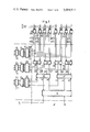
- FIG. 1 shows an arrangement which operates according to the principle of continuous coding
- FIG. 2 shows the construction of a connection circuit and an identification device which are used in an arrangement as shown in FIG. 1;
- FIG. 3 illustrates the identification and coding process of continuous coding of the FIG. 1 embodiment
- FIG. 4 shows an arrangement which operates by the principle of stage-by-stage coding
- FIG. 5 shows the construction of a connection circuit and an identification circuit which are employed in an arrangement as shown in FIG. 4;
- FIG. 6 shows the construction of a control circuit for the connection of the additional stores which are used in an arrangement as shown in FIG. 4;
- FIG. 7 shows a part of the arrangement shown in FIG. 4 with the aid of which an identification and coding process in stage-by-stage coding will be described in detail;
- FIG. 8 shows, in the form of a flow diagram, the pulse train sequence for an identification and coding process in stage-by-stage coding.
- FIG. 1 DESCRIPTION OF PREFERRED EMBODIMENT Arrangement with Continuous Coding
- the arrangement illustrated therein is designed for 512 terminals or lines which are referenced L.
- Each line L is assigned a connection circuit SAOOO to SASl l.
- the storage devices which serve to receive items of information 10 occurring on the lines are provided in the connection circuits.
- the identification takes place with the aid of the identification devices which are arranged in stages in 15 accordance with the known coordinate principle.
- each case there is in each case provided a stage with a series of identification devices.
- the present example is based on a three position octal code. This means that for 8 512 connection circuits in the first stage, in each case 8 64 identification devices are provided in the second stage, namely the identification devices E00 to E63; eight connection circuits of the first stage are connected to one identification device in the second stage. In each case eight identification devices in the second stage are each assigned one identification device A0 to A7 in the third stage. In each case eight identification devices in the third stage are in turn assigned an identification device S0 in the fourth stage.
- each identification device has one input and output in the direction of the following or the next higher stage. Furthermore each identification device is connected via an identification line to a coder provided in each stage. If necessary the coders are in each case preceded by mixer circuits. The coding results are stored in registers.
- the mixer circuit ME For the coding and storage of the identification result of the first stage (units digits of the selected code) the mixer circuit ME, the coder CE and the register RE are provided. The coding and the storage of the identification result of the second stage (tens digit of the code) is carried out via the mixer circuit MA, the coder CA and the register RA. In the third stage these functions are assumed by the mixer circuit MS, the coder CS and the register RS.
- the transfer by groups of items of information occurring on the lines L is carried out with the pulse train T1 which will be referred to as an interrogation pulse train in the following. Together with the interrogation pulse train T1, in the connection circuits the items of information are stored and at the same time the request criteria are formed.
- the erasure of a request when identification has taken place is carried out, as explained later, with a pulse train T2 which will be referred to in the line L prepared appropriately to be reversed with the next interrogation pulse train T1.
- the outputs of the two trigger stages K1 and K2 are connected to the inputs of an EXCLUSIVE-OR gate G1. A criterion is emitted at the output of this gate whenever the two trigger stages K1 and K2 have different states.
- a request criterion in the form of a 1 occurs at the output of the gate G1 whenever an item of information in the form of a polarity change has actually occurred on the line L, and has been intermediately stored with the interrogation pulse train Tl. Simulta-' neously with the request criterion, and AND gates G2 and G4 are prepared.
- the identification line c000 is connected to the output of gate G2 over which the identification result passes via the units position of the relevant connection circuit to the mixer circuit ME. This information is coded in the coder CE and stored as a 3-bit code in the register RE.
- the gate G4 serves to control the second trigger stage K2 which, when identification has taken place, with the transfer pulse train T2 is brought into the position corresponding to the new polarity change on the line L; at the same time the request criterion at the output of the gate G1 is disconnected.
- connection circuits SA000 to SA007 of the first stage are connected to the identification device E in the second stage.
- the latter contains the priority logic circuit PLl with the gates G5 to G12.
- each request criterion which occurs on one of the request lines a000 to 11007 is passed via a request line a00 to an identification device which has not been shown here in the following stage.
- the OR gates G6 to GI 2 are connected to the request lines 0000 to a007 in such manner that a resetting criterion always passes only via one of the resetting lines bOOO to b007 to one of the connection circuits SAOOO to SA007.
- the sequence for identification in the present example is such that the request criterion which arrives via the request line a000 possesses the highest priority.
- an identification criterion is available which passes via the identification line COO to the mixer circuit MA illustrated in FIG. 1, is coded in the coder CA and is transferred as 3-bit code into the register RA.
- the identification device E00 receives a resetting criterion from an identification device, not shown here, in the following stage. It should be mentioned at this point that all the identification devices and all the connection circuits are constructed based ion the teachings of FIG. 2.
- a request criterion is produced in the form of a 1 in the described manner via the gate G1 in the connection circuits SA007 and SA063.
- this request criterion passes via the request line a007 to the identification device E00 in the second stage, from there via the gate G5 and the request line a00 to the identification device A0 in the third stage.
- the request criterion in the connection circuit SA063 passes as l to the identification device A0 in the third stage. This path leads via the request line (1063 to vention. If the entire request for an identification and coding process is ready, the ready criterion (B in FIG. I) will be available at the resetting input of the identification device in the highest stage. Via the identification device in the fourth stage and via the line b0 this criterion passes in the form of a 0 to the resetting input of the identification device A0.
- this criterion passes as a 0 merely to 'the connection circuit SA007.
- This path leads across the identification device A0 and the reset f ting line [700 to the identification device E00 and from 4 there via the gate G12 and the resetting line b007 to th connection circuit AS007.
- the gates G3'in the connection circuit SA007, G13 in the identification device E00 and G13 in the identification'device A0 which have been prepared by the request criterion of the connection circuit SA007 are enabled.
- the coders CE, CA and CS in known manner, form the identification result ce, ca and cs in each case in the form of a 3-bit code for -.;the first position (units position), for the second posicurrently prevailing on the line L.
- the request criterion at the output of the gate G1 is thus disconnected.
- the transfer pulse train T2 is advantageously connected simultaneously to transfer the items of information ce, ca and cs stored in the individual code registers CE, CA and CS. 0
- connection circuit SA063 G12 in A0, 1207, G12 in E07, b063, SA063
- the gates which have been prepared by the request criterion transmitted from the connection circuit SA063 are enabled.
- this is the gate G2
- the identification devices E07 and A this is in each case the gate Gl3.
- the corresponding inputs of the mixer circuits ME, MA and MS are energized.
- the identification result 02 Via the coders CE, CA and CS the identification result 02, ca and cs for each position or digit of the code are transmitted in the form of a 3-bit code into the registers RE, RA and RS.
- the transfer pulse train T2 By means of the transfer pulse train T2 on the one hand these registers are read out and on the other hand the trigger stage K2 in the connection circuit SA063 is re- Arrangement With Stage-By-Stage Coding
- FIG. 4 An exemplary embodiment which operates with stage-by-stage coding is shown in FIG. 4.
- the intermediate storage of an identification result in coded form always takes place directly in the identification devices of the individual stages.
- connection circuits SA000 to SA511 are provided and that a three-position octal code is employed for coding.
- the identification of connection circuits which emit request criteria is again carried out through a multi-stage arrangement of identification devices.
- the first stage again contains the connection circuits SA000 to SA511 to which the lines L are connected.
- the request lines r1000 to a5l1 and via the resetting lines bOOO to b5ll the latter are connected in groups of eight to the identification devices EOO to E63 in the second stage.
- Each identification device is assigned a coder CE, a decoder DE and an intermediate storing register RE.
- the identification devices E00 to E63 in the second stage are connected to the identification devices A0 to A7 in the third stage.
- These are again in each case assigned a coder CA, a decoder DA and a register RA to accomodate an item of information which has been identified in the second stage and corresponds to the so-called tens position of the connection circuit.
- KA of these registers it is again in each case noted whether an identification device in the third stage was participating in an identification process in the preceding stage.
- identification devices A0 to A7 in the third stage are connected via request lines a0 to a7 and the resetting lines to b7 to the identification device S0 of the fourth and last stage.
- the latter is also assigned a coder CS, a decoder DS and a register R5 to accomodate the information corresponding to a hundreds position of an identified connection circuit.
- the particular preceding stage is in each case reset on the transfer of the request criterion; additional stores are provided which receive the identification result of the particular preceding stage.
- these stores are realised as 3-bit registers.
- the third stage contains the registers REl to RE7 which are connected via the identification lines ceOO to c263 to the registers RE.
- a select criterion for the transfer of a 3-bit combination is emitted from the identification devices of the relevant stage; thus, in the example from the identification devices A0 to A7.
- the identification result contained in the stores REI to RE7 is, with the progression of the identification process, transferred via the identification lines 020 to ce7 to the store REll in the fourth stage.
- the identification results contained in the registers RA of the third stage here are received by the store RAl which is connected to the registers RA via the identification lines caO to ca7.
- the fourth stage there is available the information ce for the units position, the information ca for the tens position and the information cs for the hundreds position of the selected connection circuit.
- the sequence of an identification and coding process is carried out in pulse-train-controlled fashion with the aid of the interrogation pulse train T1 and the transfer pulse train T2 to T4.
- the switch-through of the pulse train T1 to T4 is dependent upon the handling of a request in the particular following stage.
- the interrogation pulse train Tl passes to the connection circuits only when the identification devices E00 to E63 in the second stage are free, which takes place e.g., through the evaluation of the signals AGSA.
- the transfer pulse train T2 with which the transfer of requests from the first stage into the second stage is controlled is connected only when the identification devices A0 to A7 in the third stage are free. This is determined by evaluating the signals AGE.
- the transfer pulse train T3 with which the transfer of a request criterion from the second into the third stage is controlled, is connected only when the identification device in the fourth stage is free which is recognized by the valuation of the signals AGA.
- the information contained in the third stage is transferred into the fourth stage with the aid of the transfer pulse train T4 only when a following stage or a following central control unit has handled the items of information which were transferred during a previous identification process.
- the signals AGSA, AGE and AGA are formed by the monitoring of the identification devices of a stage.
- connection circuit and of an identification device for this embodiment will be described making reference to FIG. 5.
- Each connection circuit in the example only the connection circuit SAOOO has been shown in detail again contains the two trigger stages K1 and K2 which via an EXCLU- SIVE-OR gate form the output for the request criterion.
- the trigger stage K1 is prepared by a polarity change occurring on the line L, and is reversed on the arrival of the interrogation pulse train Tl.
- a 1 thereupon appears which passes via the request line 11000 to the first input of the identification device E00.
- the pulse train input of the trigger stage K2 is connected to the resetting line [9000.
- the resetting criterion is emitted from the first resetting output of the identification device E00.
- the identification device E represented in FIG. contains the priority logic circuit PL2 which is composed of the gates G to G22 and which ensures that in each case only one of the eight possible request criteria is evaluated; in the present exemplary embodiment, a request criterion on the line aOOO has the highest priority.
- the coder CE which follows the priority logic circuit PL2
- the number of the selected connection circuit is converted into an item of 3-bit information. This information is offered to the intermediate-storing register RE. The transfer only takes place however with the transfer pulse train T2.
- Each request arriving in the identification device E00 leads, via the gate G15, both to the formation of the signal AGSA, with which the interrogation pulse train T1 is blocked and also the preparation of the register position KE.
- the register position KE is set with a l and also the register positions RE are set in accordance with the information formed in the coder CE. Via the decoder DE the information is decoded.
- the resetting criterion is transferred via one of the resetting lines to the selected connection circuit. In the example shown in FIG. 5 the resetting criterion is omitted via the resetting line bOOO to the connection circuit SAOOO. There the trigger stage K2 is thus reversed and the request criterion on the request line 0000 is disconnected.
- connection circuits of the group SAOOO to SAOO7 contains further requests, these are now evaluated in accordance with their values in the priority logic of the identification device E00 and converted in the coder CE into an item of 3-bit information in the same manner.
- the signal AGSA remains in existence so that no further requests are transferred until the final handling of the requests which have been received in the connection circuits on the arrival of the first interrogation pulse train T1.
- the output of the register stage KE forms the request criterion for the following identification stage. It is emitted via the request line uOO, while a resetting input of the register stage KE is connected to the resetting line bOO, via which a resetting criterion arrives from the following stage.
- the outputs of the intermediatestorage register RE are connected to the identification lines referenced ceOO in FIG. 4. All the connection circuits and all the identification devices are constructed in this way.
- the stores which serve to receive an identification result which has been intermediately stored in the par- ,ticular preceding stage can also be 3-bit registers.
- FIG. 6 As an example of the construction of and the mode of connection to the identification device of a stage, FIG. 6
- the trigger stages of the store REl are connected via the gates G23 to the identification lines ceOO to ceO7 which lead out from the registers RE of the preceding second stage.
- the gates are controlled via the priority logic circuit of the identification device, in this case via the priority logic circuit of the identification device A0.
- a request criterion which is emitted for example from the identification device E00, and which arrives via the request line 1100 is always evaluated in the priority logic circuit of the identification device AO as a highest value request criterion. All the other request criteria are not considered in this case.
- the gates G23 to G25 are enabled for the information incoming via the identification line 0200. This information is transferred under the control of the transfer pulse train T3.
- the identification devices of the entire arrangement are free.
- the pulse train input gates are enabled for the interrogation pulse train T1 and for the transfer pulse trains T2 to T4.
- the identification devices E00, E07 in the second stage, the identification device A0 in the third stage and the identification device S0 in the fourth stage participate in the identification of waiting requests.
- the connection circuits and the identification devices are constructed as described in FIGS. 5 and 6.
- a request criterion is emitted, via the request lines 0000, (1007 and a063.
- this request criterion is evaluated.
- the identification device E00 this leads to the number of the first connection unit SAOO being coded in the coder CE.
- the number of the connection unit SAO63 is coded in the identification device E07; due to the emission of the signal AGSA, the pulse train gate blocks the interrogation pulse train Tl.
- the coded identification results are transferred into the registers RE; at the same time the register position KE is set in each case.
- the number of the connection circuit transmitting the request criterion is in each case formed and, via the resetting line b000 and b063 in the relevant connection circuits the request criterion is disconnected.
- the request criterion is passed on via the request line aOO and aO7.
- the identification result intermediately stored in the registers RE is likewise passed on via the identification lines ceOO and C607 to the next stage.
- the request criteria are evaluated in the priority logic circuit PLZ in such a manner that only the request criterion which arrives via the line a00 is coded in the coder CA.
- An appropriate control criterion is fed to the control circuit STA.
- the signal AGE is produced which blocks the pulse train input of the transfer pulse train T2.
- the information which has been selected via the control circuit STA is passed into the store REl.
- the coding result is transferred into the register RA and the register position KA is set.
- the selected identification device of the preceding stage is reset via the resetting line bOO.
- the information in the store RBI and the identification result in the register RA are passed on via the identification lines ceO and caO to the next stage.
- the request criterion is at the same time passed on via the request line a to the identification device S0 of the next stage.
- the request criterion arriving via the request line a0 is evaluated in the priority logic circuit PL2, is coded in the coder CS and at the same time the signal AGA is formed with which the pulse train input for the transfer pulse train T3 is blocked.
- the control circuits STSl and STSZ are likewise controlled via the priority logic circuit.
- the information emitted from the store REl via the identification lines ceO is transferred into the store REl l.
- the items of information offered from the register RA via the lines caO are transferred into the store RAl.
- the information formed in the coder CS is transferred into the register RS, and at the same time the register position KS is also set.
- the decoder DS Via the decoder DS and via the resetting line b0 the request in the preceding stage is reset.
- the information ce concerning the units position, the information ca concerning the tens position and the information cs concerning the hundreds position of the number of the selected connection circuit SA00 is now available at the output of the fourth stage.
- This information is handled in a manner not represented here by a central control unit.
- the latter can for example be activated by the criterion A emitted by the register position KS.
- the register position KS On completion the register position KS is reset via the line b by a centrally formed signal B.
- the following interrogation pulse train T1 and the following first transfer pulse train T2 have no effects in the connection circuits SA000, SA007 and SA063 and in the identification devices E00 and E07 of the second stage, as the relevant pulse train gates are blocked via the signals AGSA and AGE. Only the pulse train gate for the transfer pulse train T3 is enabled, as the identification device SO has become free again following the transfer of the items of information contained in the stores REll and RAl and in the register RS. As the request criterion present from the request line aOO7 has not yet been processed in the identification device E00 of the second stage, said stage is set immediately following the resetting of the register position KE. Also the coding result of this further request has been transferred into the register RE.
- the request from the identification device .EOO in the second stage is again available via the line aOO.
- the described processes are re-initiated i.e., both the contents of the register RE are transferred into the register RE] and also the coding result is transferred into the register RA and at the same time the register position KA is set again.
- the identification device of the preceding stage A0 is reset into the original state.
- the information ce, ca and cs concerning the units, tens and hundreds position of the connection circuit SA063 is now available at the output of the identification device S0.
- the pulse train gates for the pulse trains T1, T2 and T3 are enabled.
- the next group of interrogation process is started. All the polarity changes which have occurred in the meantime on the lines L are transferred into the connection circuits and lead to the formation of new request criteria.
- the pulse train control shown in FIG. 8 in the form of a simplified flow diagram, of the identification and coding processes permits, when identification and coding arrangement are provided in duplicate, a comparison of results at all pulse train times.
- identification and coding arrangement are provided in duplicate, a comparison of results at all pulse train times.
- connection circuits include storage devices and gate switching elements, the items of information occurring on the lines being transferred into the storage devices in groups in response to a central interrogation pulse train, the gate switching elements being responsive to the occurence of one of said items to emit a request criterion, a series of decentralized identification devices arranged in stages in accordance with coordinate principles, each stage including means for identifying one digit of the code characterizing the connection circuit emitting the requests and connected request and resetting lines connecting said identification devices in successive stages, and coding switching elements for coding the identification result of each stage and registers coupled to said coders for storing the results of said coding, said registers holding the resultant identification of said request.
- said coding switching elements and said registers for the intermediate storage of the identification result for all the connection circuits comprises a common coder and a common register for each of said stages, that the coder of the first stage is connected via identification lines to all the connection circuits, and the coders of the following stages, are connected via identification lines to the identification devices of the relevant stage with which the coder and register are associated.
- each identification device further comprises a priority logic circuit including means for switching through to the identification device of the next succeeding stage only the highest value arriving request criterion, the transmission of a resetting criterion emitted from an identification device of the following stage to the preceding stage being contemporaneously interrupted, each identification device including a gate circuit prepared by the request criterion and responsive to the disconnection of the resetting criterion to connect the identification device of the relevant stage to the identification line for the emission of the identification result.
- each identification device comprises a coder and a register connected to the output of said coder for coding and the intermediate storage of the identification result by a transfer pulse train, means controlled by passing the request criterion via the request line to the following stage, and the intermediately stored identification result from the register via the identification lines to an additional storage device in the following stage, and transmitting the resetting criterion via the resetting line to the preceding stage.
- each identification device contains a priority logic circuit for the selection of the particular highest value request criterion, said priority logic circuit including an additional position in the intermediately storing register and means for producing during each selection process a signal and blocks for preparing the storing register and for blocking the input of the transfer pulse train to the preceding stage, and including a decoder for decoding the intermediately stored identification result for forming a resetting criterion.
- the storage device of a connection circuit comprises two bistable trigger stages, that the first trigger stage is prepared in accordance with the information occurring on the line connected thereto and is responsive to the interrogation pulse train, whereas the second trigger stage is responsive to the resetting criterion, so that when the second trigger stage is reversed by said resetting criterion, the request criterion of the relevant connection circuit is disconnected.
- connection circuit including gate means having inputs connected to the request line, the resetting line and the transfer train and an output connected to the pulse train input of the second trigger stage for reversing said second trigger stage and disconnecting said request criterion.
Landscapes
- Engineering & Computer Science (AREA)
- Computer Networks & Wireless Communication (AREA)
- Signal Processing (AREA)
- Communication Control (AREA)
- Data Exchanges In Wide-Area Networks (AREA)
- Signal Processing For Digital Recording And Reproducing (AREA)
Applications Claiming Priority (1)
| Application Number | Priority Date | Filing Date | Title |
|---|---|---|---|
| DE19732348255 DE2348255C3 (de) | 1973-09-25 | Anordnung zur Identifizierung von Anforderungen in programmgesteuerten Datenvermittlungsanlagen |
Publications (1)
| Publication Number | Publication Date |
|---|---|
| US3909511A true US3909511A (en) | 1975-09-30 |
Family
ID=5893619
Family Applications (1)
| Application Number | Title | Priority Date | Filing Date |
|---|---|---|---|
| US508620A Expired - Lifetime US3909511A (en) | 1973-09-25 | 1974-09-23 | Arrangement for the identification of requests in program-controlled data switching systems |
Country Status (14)
| Country | Link |
|---|---|
| US (1) | US3909511A (de) |
| AT (1) | AT338883B (de) |
| BE (1) | BE820319A (de) |
| BR (1) | BR7407917D0 (de) |
| CA (1) | CA1048133A (de) |
| CH (1) | CH585489A5 (de) |
| FI (1) | FI60803C (de) |
| FR (1) | FR2245138B1 (de) |
| GB (1) | GB1479939A (de) |
| IN (1) | IN140575B (de) |
| IT (1) | IT1022237B (de) |
| NL (1) | NL7412315A (de) |
| SE (1) | SE393507B (de) |
| ZA (1) | ZA745070B (de) |
Families Citing this family (2)
| Publication number | Priority date | Publication date | Assignee | Title |
|---|---|---|---|---|
| GB2127187B (en) * | 1982-08-23 | 1986-03-05 | Hewlett Packard Co | Circuits for operating on n-digit operands |
| US4623982A (en) | 1985-06-10 | 1986-11-18 | Hewlett-Packard Company | Conditional carry techniques for digital processors |
Citations (5)
| Publication number | Priority date | Publication date | Assignee | Title |
|---|---|---|---|---|
| US3300759A (en) * | 1962-08-21 | 1967-01-24 | Johnson Service Co | Binary logic coded control |
| US3529293A (en) * | 1967-04-10 | 1970-09-15 | Leeds & Northrup Co | Supervisory and control system |
| US3531772A (en) * | 1968-02-16 | 1970-09-29 | Bell Telephone Labor Inc | Selective calling line controller for detecting and generating code characters |
| US3571798A (en) * | 1968-11-13 | 1971-03-23 | Ibm | Two level switching system |
| US3717723A (en) * | 1969-09-12 | 1973-02-20 | Siemens Ag | Process and apparatus for the selection and interrogation of connections in dial exchange data systems with central programable control |
-
1974
- 1974-07-26 GB GB33092/74A patent/GB1479939A/en not_active Expired
- 1974-08-06 AT AT642874A patent/AT338883B/de active
- 1974-08-08 ZA ZA00745070A patent/ZA745070B/xx unknown
- 1974-08-14 CA CA207,013A patent/CA1048133A/en not_active Expired
- 1974-09-17 CH CH1262574A patent/CH585489A5/xx not_active IP Right Cessation
- 1974-09-17 NL NL7412315A patent/NL7412315A/xx not_active Application Discontinuation
- 1974-09-17 FI FI2713/74A patent/FI60803C/fi active
- 1974-09-19 IN IN2088/CAL/74A patent/IN140575B/en unknown
- 1974-09-23 FR FR7432033A patent/FR2245138B1/fr not_active Expired
- 1974-09-23 US US508620A patent/US3909511A/en not_active Expired - Lifetime
- 1974-09-24 BR BR7917/74A patent/BR7407917D0/pt unknown
- 1974-09-24 IT IT27613/74A patent/IT1022237B/it active
- 1974-09-24 SE SE7411983A patent/SE393507B/xx not_active IP Right Cessation
- 1974-09-25 BE BE148873A patent/BE820319A/xx unknown
Patent Citations (5)
| Publication number | Priority date | Publication date | Assignee | Title |
|---|---|---|---|---|
| US3300759A (en) * | 1962-08-21 | 1967-01-24 | Johnson Service Co | Binary logic coded control |
| US3529293A (en) * | 1967-04-10 | 1970-09-15 | Leeds & Northrup Co | Supervisory and control system |
| US3531772A (en) * | 1968-02-16 | 1970-09-29 | Bell Telephone Labor Inc | Selective calling line controller for detecting and generating code characters |
| US3571798A (en) * | 1968-11-13 | 1971-03-23 | Ibm | Two level switching system |
| US3717723A (en) * | 1969-09-12 | 1973-02-20 | Siemens Ag | Process and apparatus for the selection and interrogation of connections in dial exchange data systems with central programable control |
Also Published As
| Publication number | Publication date |
|---|---|
| FI60803C (fi) | 1982-03-10 |
| SE393507B (sv) | 1977-05-09 |
| ATA642874A (de) | 1977-01-15 |
| FR2245138A1 (de) | 1975-04-18 |
| FR2245138B1 (de) | 1977-07-08 |
| AU7209574A (en) | 1976-02-12 |
| IT1022237B (it) | 1978-03-20 |
| BR7407917D0 (pt) | 1975-07-29 |
| DE2348255A1 (de) | 1975-04-03 |
| NL7412315A (nl) | 1975-03-27 |
| DE2348255B2 (de) | 1976-08-19 |
| FI60803B (fi) | 1981-11-30 |
| CH585489A5 (de) | 1977-02-28 |
| GB1479939A (en) | 1977-07-13 |
| ZA745070B (en) | 1975-08-27 |
| SE7411983L (de) | 1975-03-26 |
| AT338883B (de) | 1977-09-26 |
| CA1048133A (en) | 1979-02-06 |
| BE820319A (fr) | 1975-03-25 |
| FI271374A7 (de) | 1975-03-26 |
| IN140575B (de) | 1976-12-04 |
Similar Documents
| Publication | Publication Date | Title |
|---|---|---|
| US3805038A (en) | Data handling system maintenance arrangement for processing system fault conditions | |
| US4213201A (en) | Modular time division switching system | |
| US4090034A (en) | Usage-sensitive billing arrangement for private branch exchange subscribers | |
| US3652993A (en) | Rapid polling method for digital communications network | |
| US3591722A (en) | Circuit arrangement for data processing telephone exchange installations with systems for message transmission | |
| US4641303A (en) | Method and circuit arrangement for the transmission of data signal bits occurring with a first bit rate in a bit stream having a second bit rate which is higher than the first bit rate | |
| US3749839A (en) | Tdm telecommunication system for transmitting data or telegraphic signals | |
| US4313198A (en) | Synchronous demultiplexer with elastic bit store for TDM/PCM telecommunication system | |
| US4386425A (en) | Switching unit for the transfer of digitized signals in PCM system | |
| US3366737A (en) | Message switching center for asynchronous start-stop telegraph channels | |
| US3909511A (en) | Arrangement for the identification of requests in program-controlled data switching systems | |
| US4394759A (en) | Transmitting section of PCM station | |
| US3644896A (en) | Modem controller | |
| US2108140A (en) | Telephone system | |
| US3553384A (en) | Telephone switching unit with local and remote computer control | |
| US3268669A (en) | Common control for remote telephone switch units | |
| US4192966A (en) | Circuit arrangement for determining specific characters occurring directly consecutively in a sequence of characters, in particular for teleprinter exchange systems | |
| US3702380A (en) | Queue for electronic telephone exchange | |
| US3347992A (en) | Circuit arrangement controlling the release of lines in a communication system | |
| US4002851A (en) | Telecommunication system controlled by stored program instructions | |
| US3385931A (en) | Error detecting circuits for telephone register and sender apparatus | |
| GB1279330A (en) | Switching system controlled by a stored program | |
| US3689701A (en) | Multisignaller associated with a time division multiplex switching center | |
| GB1125563A (en) | Improvements in or relating to automatic switching systems | |
| US3686442A (en) | Process and circuit arrangement for the transmission of message signals, in particular pcm message signals, from a transmission station to a receiving station |