US3887328A - Heat treatment apparatus - Google Patents
Heat treatment apparatus Download PDFInfo
- Publication number
- US3887328A US3887328A US439330A US43933074A US3887328A US 3887328 A US3887328 A US 3887328A US 439330 A US439330 A US 439330A US 43933074 A US43933074 A US 43933074A US 3887328 A US3887328 A US 3887328A
- Authority
- US
- United States
- Prior art keywords
- supply pipe
- rotatable
- pipe
- axis
- radial
- Prior art date
- Legal status (The legal status is an assumption and is not a legal conclusion. Google has not performed a legal analysis and makes no representation as to the accuracy of the status listed.)
- Expired - Lifetime
Links
- 238000010438 heat treatment Methods 0.000 title claims abstract description 50
- 239000002184 metal Substances 0.000 claims abstract description 36
- 239000012530 fluid Substances 0.000 claims description 10
- 238000010276 construction Methods 0.000 claims description 7
- 230000000295 complement effect Effects 0.000 claims description 4
- 238000003780 insertion Methods 0.000 abstract description 2
- 230000037431 insertion Effects 0.000 abstract description 2
- 238000000034 method Methods 0.000 description 3
- 230000001105 regulatory effect Effects 0.000 description 3
- 238000003466 welding Methods 0.000 description 3
- ATUOYWHBWRKTHZ-UHFFFAOYSA-N Propane Chemical compound CCC ATUOYWHBWRKTHZ-UHFFFAOYSA-N 0.000 description 2
- QVGXLLKOCUKJST-UHFFFAOYSA-N atomic oxygen Chemical compound [O] QVGXLLKOCUKJST-UHFFFAOYSA-N 0.000 description 2
- 239000000446 fuel Substances 0.000 description 2
- 239000007789 gas Substances 0.000 description 2
- 239000008246 gaseous mixture Substances 0.000 description 2
- 239000001301 oxygen Substances 0.000 description 2
- 229910052760 oxygen Inorganic materials 0.000 description 2
- 229920002379 silicone rubber Polymers 0.000 description 2
- 239000004945 silicone rubber Substances 0.000 description 2
- 241000237519 Bivalvia Species 0.000 description 1
- 239000003795 chemical substances by application Substances 0.000 description 1
- 235000020639 clam Nutrition 0.000 description 1
- 238000002485 combustion reaction Methods 0.000 description 1
- 230000006835 compression Effects 0.000 description 1
- 238000007906 compression Methods 0.000 description 1
- 230000007547 defect Effects 0.000 description 1
- 210000004907 gland Anatomy 0.000 description 1
- 239000001294 propane Substances 0.000 description 1
Images

Classifications
-
- B—PERFORMING OPERATIONS; TRANSPORTING
- B23—MACHINE TOOLS; METAL-WORKING NOT OTHERWISE PROVIDED FOR
- B23K—SOLDERING OR UNSOLDERING; WELDING; CLADDING OR PLATING BY SOLDERING OR WELDING; CUTTING BY APPLYING HEAT LOCALLY, e.g. FLAME CUTTING; WORKING BY LASER BEAM
- B23K9/00—Arc welding or cutting
- B23K9/235—Preliminary treatment
-
- C—CHEMISTRY; METALLURGY
- C21—METALLURGY OF IRON
- C21D—MODIFYING THE PHYSICAL STRUCTURE OF FERROUS METALS; GENERAL DEVICES FOR HEAT TREATMENT OF FERROUS OR NON-FERROUS METALS OR ALLOYS; MAKING METAL MALLEABLE, e.g. BY DECARBURISATION OR TEMPERING
- C21D9/00—Heat treatment, e.g. annealing, hardening, quenching or tempering, adapted for particular articles; Furnaces therefor
- C21D9/08—Heat treatment, e.g. annealing, hardening, quenching or tempering, adapted for particular articles; Furnaces therefor for tubular bodies or pipes
-
- C—CHEMISTRY; METALLURGY
- C21—METALLURGY OF IRON
- C21D—MODIFYING THE PHYSICAL STRUCTURE OF FERROUS METALS; GENERAL DEVICES FOR HEAT TREATMENT OF FERROUS OR NON-FERROUS METALS OR ALLOYS; MAKING METAL MALLEABLE, e.g. BY DECARBURISATION OR TEMPERING
- C21D9/00—Heat treatment, e.g. annealing, hardening, quenching or tempering, adapted for particular articles; Furnaces therefor
- C21D9/50—Heat treatment, e.g. annealing, hardening, quenching or tempering, adapted for particular articles; Furnaces therefor for welded joints
-
- F—MECHANICAL ENGINEERING; LIGHTING; HEATING; WEAPONS; BLASTING
- F23—COMBUSTION APPARATUS; COMBUSTION PROCESSES
- F23D—BURNERS
- F23D23/00—Assemblies of two or more burners
Definitions
- Heat treatment apparatus for heating the internal surface of a metal pipe has an adjustable frame which is adapted for insertion within the pipe for variation in [30] Fol-mg Apphc au0n Pn0my Dam length perpendicular to the axis of the pipe.
- a pneu- 1973 Umted Kingdom 6129/73 matic motor is drivably connected to a rotatable supply pipe for a combustible gaseous medium mounted CL 432/224; 266/23 K; 266/23 M within the adjustable frame.
- Radial supply pipes ex- [5 Cl.
- the invention relates to heat treatment apparatus for the internal surface of a metal pipe.
- the internal heating has been carried out with a circular radiant heater which is mounted centrally within the pipe to be treated by means of three or more radially extending stays which engage the internal surface of the pipe.
- Variation in heating, for pipes having different wall thicknesses is controlled by varying the supply of combustible gaseous medium supplied to the heater because the heater is always located at a fixed distance from the internal surface of the pipe by the radially extending stays. Not only is this method of control cumbersome, it also tends to accentuate the major disadvantage of this method of heat treatment.
- heat treatment apparatus for heating the internal surface of a metal pipe, comprising at least one heater, such as a radiant heater, mounted at one end of a radial supply pipe for a combustible gaseous medium, the radial sup ply pipe extending perpendicularly from the axis of a rotatable supply pipe which is alignable with the axis of the metal pipe.
- a heater such as a radiant heater
- the radial supply pipe is of telescopic construction so as to allow adjustment of the heater for heating the internal surfaces of pipes of different diameters and may thus include a socket portion which is clamped to the rotatable supply pipe and extends equally on both sides of the rotatable supply pipe and an inner portion which extends from one end of the socket portion and is of the same length as the socket portion, the rotatable supply line being communica tively connected to the radial supply pipe by means of a branch pipe connected to the other end of the socket portion of the radial supply pipe.
- the or each heater may be held in very close proximity to the internal surface of the pipe so as to ensure much more radiant heating of this surface.
- the extent of heating can be controlled by varying the duration of heating and the speed of the or each heater as it rotates within the pipe.
- the rotatable supply pipe may be disposed below the axis of the metal pipe so that any convective heating of the upper part of the pipe may be counterbalanced by greater radiant heating of the lower part of the pipe.
- the rotatable supply pipe is mounted in an adjustable frame which is capable of variation in length perpendicular to the axis of the rotatable supply pipe and, in a preferred construction, the adjustable frame has two rectangular ends supported by telescopic legs and bearing spring loaded wheels which are engageable with the internal surface of the pipe so as to allow axial movement of the frame along the metal pipe.
- Each rectangular end may be supported at its corners by telescopic legs which each have at least two telescopically connected portions and clamps for locking each co-operating pair of inner and outer portions.
- each clamp includes a locking pad accommodated within a recess formed internally of the ring for engagement with the inner end of the adjusting screw and extending through an aperture formed in the outer portion of the telescopic leg for locking engagement with the inner portion of the telescopic leg, the locking pad having an inner surface which is complementary to the external surface of the inner portion.
- the rotary drive of the rotatable sup ply pipe may be provided by a pneumatic motor.
- the adjustable frame may therefore support a housing which encloses a pneumatic motor, a reduction drive connecting the pneumatic motor to the rotatable supply pipe, and bearings supporting the rotatable supply pipe.
- a mixing chamber may be mounted within the housing on one end of the rotatable supply pipe and connected to two inlet pipes provided with regulating valves for supplying, respectively, a gaseous fuel and oxygen to the rotatable supply pipe and it is possible that one of the gaseous media supplied to the mixing chamber may be first passed through the pneumatic motor to provide the rotary drive.
- FIG. 1 is a schematic perspective view of the apparatus
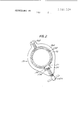
- FIG. 2 is an end view of a clamp forming part of the apparatus.
- two heaters 17, such as gas burners, are mounted on two radial supply pipes 15A, 15B projecting perpendicularly from a rotatable supply pipe 10, for rotation within metal pipes 21 and 22 to heat the metal in the region of the junction between these two pipes.
- the rotatable supply pipe 10 is aligned with the axes of the pipes 21 and 22 and supported in bearings 7 and 11 mounted in a housing 30 (only partly shown) forming part of an adjustable frame 23 which is supported for axial movement along the pipes 21 and 22 on wheels 18.
- Compressed air fed through a line 3 is fed to a pneumatic motor 4 provided with an integral reduction drive 5 and a pinion 9A mounted on the output shaft (not shown) of the reduction drive 5 meshes with a gear wheel 98 to provide a further speed reduction.
- the gear wheel 9B is non-rotatably connected to the rotatable supply pipe 10 so as to be rotatable by the pneumatic motor 4.
- Compressed air and propane are fed through pipes 1A and 2A provided with regulating valves 1 and 2 to a mixing chamber 6.
- the open end of the rotatable sup ply pipe 10 is enclosed by the mixing chamber 6 and a seal (not shown) prevents leakage of gas from the mixing chamber 6 around the outside of the rotatable supply pipe 10.
- the combustible gaseous mixture is thus fed through the rotatable supply pipe 10 into a manifold chamber 12 and, through branch lines 13A and 138 provided with stop valves 14A and 148, to the ends of two socket portions 15A of the radial supply pipes carrying the heaters 17.
- the two socket portions 15A are carried in a clamp 10A at the end of the rotatable supply pipe 10 and extend equally on opposite sides of the clamp 10A.
- Inner portions 158 of the radial supply lines, which are communicatively connected to the burners 17, are slideable in the socket portions 15A and secured in position by compression glands 16 which co-operate with silicone rubber O-rings (not shown).
- a further silicone rubber O-rings (not shown) is mounted between the inner end of each inner portion 158 and the enclosing socket portion 15A.
- the combustible gaseous mix ture fed to the burners 17 can therefore be burnt to provide radiant heating and the speed of rotation of the burners may be varied between 0 and 12 rpm. so as to control the extent of heatingv
- the socket portion 15A and the inner portion 158 of the radial supply pipe are both 2 feet in length so that the heat treating apparatus is capable of heating pipes which vary substantially in diameter.
- the supporting wheels 18 of the adjustable frame 23 are mounted at opposite ends of two leaf springs 18B which are mounted at axially opposite ends of rectangular ends 23A of the adjustable frame 23 and the four corners of each end 23A are supported by telescopic legs 24A, 24B, 24C which are connected to the housing 30 by means of brackets 31 and plates 32 (only partly shown).
- each clamp for locking together each co-operating pair of inner and outer portions 24A, 248 or 24B, 24C of each telescopic leg of the adjustable frame 23 has a ring 25 which is secured to the outside of the outer portion 24A (as shown in FIG. 2) by means of a locking screw 26A and secured to the inner portion 243 (as shown in FIG. 2) by means of an adjustment screw 268 which extends in screwthreaded engagement through a radial aperture formed in the ring 25 into abutment with a locking pad 27 which is accommodated in a recess 28 formed internally of the ring 25.
- the locking pad 27 has an inner surface 27A which is complementary to the external surface of the portion 248 and extends through an aperture 29 formed in the outer portion 28.
- Heat treatment apparatus for heating the internal surface of a metal pipe, comprising a rotatable supply pipe for a gaseous fluid which is alignable with the axis of the metal pipe, at least one radial supply pipe for the gaseous fluid extending perpendicularly from the axis of the rotatable supply pipe, a heater mounted at one end of the radial supply pipe, the radial supply pipe being of telescopic construction and having a socket portion which is clamped to the rotatable supply pipe and extends equally on both sides of the rotatable supply pipe and an inner portion which extends from one end of the socket portion and is of substantially the same length as the socket portion, and a branch supply pipe connected between the other end of the socket portion of the radial supply pipe and the rotatable sup- P y P p 2.
- Heat treatment apparatus according to claim 1, in which an adjustable frame which is capable of variation in length perpendicular to the axis of the rotatable supply pipe supports the rotatable supply pipe.
- Heat treatment apparatus for heating the internal surface of a metal pipe, comprising a rotatable supply pipe for a gaseous fluid which is alignable with the axis of the metal pipe, at least one radial supply pipe extending perpendicularly from the axis of the rotatable supply pipe, a heater mounted at one end of the radial supply pipe, and adjustable frame means supporting thereon the rotatable support pipe and capable of variation in length perpendicular to the axis of the rotatable supply pipe, said adjustable frame means having two rectangular ends supported by telescopic legs and bearing spring loaded wheels which are engageable with the internal surface of the metal pipe so as to allow axial movement of the frame means along the metal pipe.
- each rectangular end of the adjustable frame means is supported at its corners by four telescopic legs which each have at least two telescopically connected portions and clamps for locking each co-operating pair of inner and outer telescopically connected portions.
- each clamp comprises a ring surrounding an outer portion of a telescopic leg, an adjustment screw in screw-threaded engagement with a radial aperture through the ring, a locking pad accommodated in a recess formed internally of the ring for engagement with the inner end of the adjustment screw and extending through an aperture formed in the outer portion of the telescopic leg for locking engagement with the cooperating inner portion of the telescopic leg, the locking pad having an inner surface complementary to the external surface of the inner portion.
- Heat treatment apparatus for heating the internal surface of a metal pipe, comprising a rotatable supply pipe for a gaseous fluid which is alignable with the axis of the metal pipe, at least one radial supply pipe extending perpendicularly from the axis of the rotatable supply pipe, a heater mounted at one end of the radial supply pipe, and adjustable frame means supporting thereon the rotatable and capable of variation in length perpendicular to the axis of the rotatable supply pipe, the adjustable frame means supporting a housing which on one end of the rotatable supply pipe and connected to two inlet pipes provided with regulating valves for supplying, respectively, a gaseous fuel and oxygen to the rotatable supply pipe.
Landscapes
- Engineering & Computer Science (AREA)
- Chemical & Material Sciences (AREA)
- Mechanical Engineering (AREA)
- Physics & Mathematics (AREA)
- Materials Engineering (AREA)
- Thermal Sciences (AREA)
- Crystallography & Structural Chemistry (AREA)
- Metallurgy (AREA)
- Organic Chemistry (AREA)
- Combustion & Propulsion (AREA)
- General Engineering & Computer Science (AREA)
- Plasma & Fusion (AREA)
- Heat Treatment Of Articles (AREA)
- Furnace Details (AREA)
Applications Claiming Priority (1)
| Application Number | Priority Date | Filing Date | Title |
|---|---|---|---|
| GB612973A GB1446442A (en) | 1973-02-08 | 1973-02-08 | Heat treatment apparatus |
Publications (1)
| Publication Number | Publication Date |
|---|---|
| US3887328A true US3887328A (en) | 1975-06-03 |
Family
ID=9808959
Family Applications (1)
| Application Number | Title | Priority Date | Filing Date |
|---|---|---|---|
| US439330A Expired - Lifetime US3887328A (en) | 1973-02-08 | 1974-02-04 | Heat treatment apparatus |
Country Status (6)
| Country | Link |
|---|---|
| US (1) | US3887328A (enExample) |
| CA (1) | CA1013566A (enExample) |
| DE (1) | DE2405722A1 (enExample) |
| FR (1) | FR2217426B1 (enExample) |
| GB (1) | GB1446442A (enExample) |
| NL (1) | NL7401667A (enExample) |
Cited By (5)
| Publication number | Priority date | Publication date | Assignee | Title |
|---|---|---|---|---|
| US4257831A (en) * | 1978-06-12 | 1981-03-24 | Vinzenz Siller | Process for the continuous hardening of pump casings |
| US4298189A (en) * | 1978-06-12 | 1981-11-03 | Vinzenz Siller | Apparatus for the continuous hardening of pump casings |
| ITPC20130001A1 (it) * | 2013-01-09 | 2014-07-10 | T A C I Di Spinello Ivo & C S N C Sa | Attrezzatura per il riscaldamento di corpi tubolari |
| US9669580B2 (en) | 2011-11-09 | 2017-06-06 | Saipem S.P.A. | Method and apparatus for heating heat-shrinkable pipe sleeves |
| WO2022056044A1 (en) * | 2020-09-08 | 2022-03-17 | Mcweeney Gerard | Methods and apparatus for metal structure fabrication |
Families Citing this family (2)
| Publication number | Priority date | Publication date | Assignee | Title |
|---|---|---|---|---|
| FR2574523B1 (fr) * | 1984-12-06 | 1987-01-30 | Chauffage Distance Cie Gle | Procede de pose de canalisations formees de troncons raccordes et canalisations realisees selon ce procede |
| CN111411213B (zh) * | 2020-03-16 | 2022-01-25 | 甘肃电投常乐发电有限责任公司 | 一种堵阀对接焊缝内外壁同时电感应热处理工艺 |
Citations (2)
| Publication number | Priority date | Publication date | Assignee | Title |
|---|---|---|---|---|
| US2058388A (en) * | 1933-07-14 | 1936-10-20 | Spang Chalfant & Co Inc | Method and apparatus for descaling metal |
| US3675905A (en) * | 1970-09-17 | 1972-07-11 | Dorn Co V | Method and apparatus for infrared heating |
Family Cites Families (2)
| Publication number | Priority date | Publication date | Assignee | Title |
|---|---|---|---|---|
| FR978347A (fr) * | 1948-04-17 | 1951-04-12 | Firestone Tire & Rubber Co | Perfectionnements aux appareils pour la soudure |
| FR2087526A5 (enExample) * | 1970-05-22 | 1971-12-31 | Cme |
-
1973
- 1973-02-08 GB GB612973A patent/GB1446442A/en not_active Expired
-
1974
- 1974-02-04 US US439330A patent/US3887328A/en not_active Expired - Lifetime
- 1974-02-04 CA CA191,683A patent/CA1013566A/en not_active Expired
- 1974-02-06 FR FR7403930A patent/FR2217426B1/fr not_active Expired
- 1974-02-06 DE DE19742405722 patent/DE2405722A1/de active Pending
- 1974-02-07 NL NL7401667A patent/NL7401667A/xx unknown
Patent Citations (2)
| Publication number | Priority date | Publication date | Assignee | Title |
|---|---|---|---|---|
| US2058388A (en) * | 1933-07-14 | 1936-10-20 | Spang Chalfant & Co Inc | Method and apparatus for descaling metal |
| US3675905A (en) * | 1970-09-17 | 1972-07-11 | Dorn Co V | Method and apparatus for infrared heating |
Cited By (7)
| Publication number | Priority date | Publication date | Assignee | Title |
|---|---|---|---|---|
| US4257831A (en) * | 1978-06-12 | 1981-03-24 | Vinzenz Siller | Process for the continuous hardening of pump casings |
| US4298189A (en) * | 1978-06-12 | 1981-11-03 | Vinzenz Siller | Apparatus for the continuous hardening of pump casings |
| US9669580B2 (en) | 2011-11-09 | 2017-06-06 | Saipem S.P.A. | Method and apparatus for heating heat-shrinkable pipe sleeves |
| ITPC20130001A1 (it) * | 2013-01-09 | 2014-07-10 | T A C I Di Spinello Ivo & C S N C Sa | Attrezzatura per il riscaldamento di corpi tubolari |
| EP2754959A1 (en) * | 2013-01-09 | 2014-07-16 | S.A.T.A.C.I. di Spinello Ivo & C. S.n.c. | Apparatus for heating tubular bodies |
| WO2022056044A1 (en) * | 2020-09-08 | 2022-03-17 | Mcweeney Gerard | Methods and apparatus for metal structure fabrication |
| EP4211278A4 (en) * | 2020-09-08 | 2025-01-08 | Mcweeney, Gerard | Methods and apparatus for metal structure fabrication |
Also Published As
| Publication number | Publication date |
|---|---|
| FR2217426A1 (enExample) | 1974-09-06 |
| FR2217426B1 (enExample) | 1978-01-06 |
| CA1013566A (en) | 1977-07-12 |
| NL7401667A (enExample) | 1974-08-12 |
| DE2405722A1 (de) | 1974-08-22 |
| GB1446442A (en) | 1976-08-18 |
Similar Documents
| Publication | Publication Date | Title |
|---|---|---|
| US3887328A (en) | Heat treatment apparatus | |
| US2255540A (en) | Combustion apparatus | |
| US3794459A (en) | Furnace exhaust treatment system | |
| RU2109069C1 (ru) | Горелка металлообрабатывающей печи и способ ее эксплуатации | |
| AU5814480A (en) | Gas mixing apparatus | |
| EP0328418A1 (en) | Radiant tube furnace and method of burning a fuel | |
| RU2010114753A (ru) | Устройство и способ нагревания металлического материала | |
| CN202367364U (zh) | 封头堆焊用火焰加热装置 | |
| US3264732A (en) | Method of welding | |
| CN207873452U (zh) | 一种深海油气框架加工用旋转加热装置 | |
| US2849220A (en) | Industrial furnace with removable combustion tubes | |
| US2340120A (en) | Pressure heating device | |
| JP4934828B2 (ja) | 窒化炉および窒化処理方法 | |
| US2146410A (en) | Heater for furnaces and method of operating the same | |
| SU1217530A1 (ru) | Устройство дл закатки концов трубчатых заготовок | |
| SU821513A1 (ru) | Установка дл термообработки кольцевыхСВАРНыХ шВОВ пОлыХ издЕлий | |
| US1232756A (en) | Liquid-fuel burner. | |
| US3372916A (en) | Apparatus for stress-relieving pipe welds | |
| CN109916778A (zh) | 一种恒温恒压扩散实验装置 | |
| CN219141512U (zh) | 炉口冷却装置及钛白粉生产设备 | |
| CN121229903B (zh) | 一种多通道双涡流回转窑用燃烧器 | |
| CN102962611A (zh) | 大型厚壁工件动态焊接加热装置 | |
| KR100581260B1 (ko) | 이동식 가스 열처리 버너장치 | |
| JP2773250B2 (ja) | 塗覆装用加熱装置 | |
| US2293756A (en) | Gas burner |