US3881663A - Roll mill for flaking grain and the like - Google Patents
Roll mill for flaking grain and the like Download PDFInfo
- Publication number
- US3881663A US3881663A US442462A US44246274A US3881663A US 3881663 A US3881663 A US 3881663A US 442462 A US442462 A US 442462A US 44246274 A US44246274 A US 44246274A US 3881663 A US3881663 A US 3881663A
- Authority
- US
- United States
- Prior art keywords
- rolls
- housing
- grain
- mill
- slots
- Prior art date
- Legal status (The legal status is an assumption and is not a legal conclusion. Google has not performed a legal analysis and makes no representation as to the accuracy of the status listed.)
- Expired - Lifetime
Links
- 230000000712 assembly Effects 0.000 claims abstract description 31
- 238000000429 assembly Methods 0.000 claims abstract description 31
- 230000009977 dual effect Effects 0.000 claims description 17
- 230000007246 mechanism Effects 0.000 claims description 6
- 239000002184 metal Substances 0.000 claims description 3
- 238000005096 rolling process Methods 0.000 claims description 2
- 238000010025 steaming Methods 0.000 abstract description 9
- 238000005452 bending Methods 0.000 abstract description 2
- 230000000694 effects Effects 0.000 description 3
- 230000003014 reinforcing effect Effects 0.000 description 3
- 230000008439 repair process Effects 0.000 description 3
- 238000010276 construction Methods 0.000 description 2
- 230000001276 controlling effect Effects 0.000 description 2
- 230000008878 coupling Effects 0.000 description 2
- 238000010168 coupling process Methods 0.000 description 2
- 238000005859 coupling reaction Methods 0.000 description 2
- 241000283690 Bos taurus Species 0.000 description 1
- WYTGDNHDOZPMIW-RCBQFDQVSA-N alstonine Natural products C1=CC2=C3C=CC=CC3=NC2=C2N1C[C@H]1[C@H](C)OC=C(C(=O)OC)[C@H]1C2 WYTGDNHDOZPMIW-RCBQFDQVSA-N 0.000 description 1
- 230000008859 change Effects 0.000 description 1
- 230000006835 compression Effects 0.000 description 1
- 238000007906 compression Methods 0.000 description 1
- 230000005484 gravity Effects 0.000 description 1
- 238000007689 inspection Methods 0.000 description 1
- 239000000463 material Substances 0.000 description 1
- 238000000034 method Methods 0.000 description 1
- 230000004048 modification Effects 0.000 description 1
- 238000012986 modification Methods 0.000 description 1
- 230000008520 organization Effects 0.000 description 1
- 230000001105 regulatory effect Effects 0.000 description 1
- 230000000284 resting effect Effects 0.000 description 1
- 238000003466 welding Methods 0.000 description 1
Images

Classifications
-
- B—PERFORMING OPERATIONS; TRANSPORTING
- B02—CRUSHING, PULVERISING, OR DISINTEGRATING; PREPARATORY TREATMENT OF GRAIN FOR MILLING
- B02C—CRUSHING, PULVERISING, OR DISINTEGRATING IN GENERAL; MILLING GRAIN
- B02C11/00—Other auxiliary devices or accessories specially adapted for grain mills
- B02C11/04—Feeding devices
-
- B—PERFORMING OPERATIONS; TRANSPORTING
- B02—CRUSHING, PULVERISING, OR DISINTEGRATING; PREPARATORY TREATMENT OF GRAIN FOR MILLING
- B02C—CRUSHING, PULVERISING, OR DISINTEGRATING IN GENERAL; MILLING GRAIN
- B02C4/00—Crushing or disintegrating by roller mills
- B02C4/28—Details
- B02C4/32—Adjusting, applying pressure to, or controlling the distance between, milling members
- B02C4/38—Adjusting, applying pressure to, or controlling the distance between, milling members in grain mills
Definitions
- a heavy duty roller mill for flaking feed grain and the [76] Inventor: Andrew Brown, 4535 E 6th like comprises a housing for enclosing a pair of heavy Ave, Denver, Colo 80220 rollers and auxiliary equlpment such as a steaming chamber.
- a flexible curved plate grain flow control- [22] Ffledi 14, 1974 ling gate is mounted-in the housing above the rolls. 2
- APPL 42 4 2 The plate is adjusted by bending effected by cam pressure.
- the housing is provided with a pair of horizontal slots in its side walls and a structural frame for carry- [52] CL 241/225; 222/410; 241/227; ing the rollers mounted in their bearing assemblies.
- 241/285 R The slots open toward one end of the mill and a re- [51] Int. Cl. B02c 11/04; B020 4/38 movable door is provided to afford movement of the [58] Field of Search 241/284, 285, 287, 230, rolls into and out of i i in the housing During 241/232 285 285 A; 222/410; 308/34 operation of the mill the slots are closed by removable closure plates. Readily released pivotal arms are pro- [56] References Cited vided for retaining the bearing assemblies in operative UNITED STATES PATENTS positions.
- ROLL MILL FOR FLAKING GRAIN AND THE LIKE My invention relates to heavy duty roller mills for flaking grain and the like and particularly to improved structural arrangements of the rolls and the grain feeding control.
- Roll mills for flaking cattle feed grain and the like commonly comprise a pair of heavy mill rolls which may weigh around one ton each, together with grain supplying and steaming equipment.
- the removal of the rolls for servicing is necessary from time to time and requires that the mill be dismantled sufficiently to afford access for lifting the rolls and removing them. This requires removal of feed control equipment and steaming chamber and other auxiliary apparatus. Substantial lost operating time is thus required for each servicing of the rolls. Accordingly it is an object of my invention to provide a heavy duty roll mill or the like including an improved arrangement for removing the rolls for servicing, repair or replacement.
- FIG. 1 is a perspective view of a flaking mill embodying my invention
- FIG. 2 is a side-elevation view of the mill of FIG. 1;
- FIG. 3 is a side elevation similar to FIG. 2 with the roll tensioning assembly removed;
- FIG. 4 is a side elevation as in FIG. 3 with the front roll in position outside the mill housing;
- FIG. 5 is aside elevation view similar to FIG. 4 with both rolls removed;
- FIG. 6 is a front elevation of the mill in the position of FIG. 4;
- FIG. 7 is an enlarged side elevation of a part of the mill as shown in FIGS. 4 and 6;
- FIG. 8 is a top plan view of the part of FIG. 7;
- FIG. 9 is a side elevation of the mill on the side opposite that of FIG. 2;
- FIG. 10 is a partial sectional elevation view taken along the line 10-10 of FIG. 6.
- the roll mill illustrated in FIGS. 1 and 2 comprises a housing 10 of generally rectangular configuration and including side walls, one of which is indicated at 11 and front and rear walls, the front wall being indicated at 12.
- the side walls extend upwardly to an attaching flange 13 and the front and rear walls are sloped toward the flange as indicated at 12a and 14.
- the steaming chamber (not shown) for steaming the grain and facilitating the flaking thereof is mounted on top of the housing 10 in engagement with the flange 13.
- the heavy duty dual roll mill comprises front and rear mill rolls mounted on shafts l5 and 16, respectively, the shafts being carried in front and rear bearing assemblies 17 and 18, respectively.
- the rollers are carried on the walls of the housing and longitudinal structural members 20 are provided for facilitating the mounting of the bearing assemblies in position.
- the bearing assemblies 17 and 18 are carried in bearing retainer arms 21 and 22 respectively, these arms being pivotally mounted on the housing on bolts or pins 23 and 24 which are securely mounted in the supporting structure includingthe member 20 and a longitudinal reinforcing member 25 which is suitably secured to the housing wall by welding or bolting or otherwise.
- the bearing assembly 17 is held rigidly in position by additional bolts 26 and 27 secured in a longitudinal members 20 and 25 after the retainer arm 21 is in position in engagement with the assembly 17.
- the bearing assemblies 17 and 18 have cylindrical body portions, this portion of the assembly 18 is indicated at 19 in FIG. 1. These assemblies include inner plates 17b and 18b, respectively and outer plates 17c and 180, respectively. The inner and outer plates of the assembly 17 and 18 are secured together against the respective cylindrical body portions by sets of six bolts 29 and 30, respectively. The cylindrical portions fit in circular or cylindrical seats in the arms 17 and 18; these seats are shown at 21a and 22a in FIG. 5. When installed on the retainer arms three of the bolts of each set pass through the arm to secure the bearing assemblies rigidly in position on their respective arms. These three bolts are removed when the mill rolls are to be moved out of the housing for servicing and the bearing assemblies must be released from the retainer arms.
- the arms 21 When securing the retainer arms 21 and 22 in position to hold the rolls in operating relationship, the arms 21 are first moved into their upright positions and bolted therein and the bearing assemblies are bolted to the arms.
- the front and rear arms 21 and 22 are then clamped in position by the tension bars 28, one on either side of the housing, and which are attached to the retainer arms 21 and 22 at their upper ends.
- the arms are drawn together by operation of handle 31 which apply tension to the rods 28 against the pressure of compression springs 32 mounted on the far side of the retaining arm 22 and of the retainer 21 and which may be adjusted by nuts 33.
- Inspection doors are provided in the front wall 12 in the lower portion of the front wall indicated at 34 and another in an inclined portion 12a in the front wall indicated at 35.
- Scraper bars are provided within the housing 10 below the rolls for clearing the product from the rolls. These bars may be adjusted by pivoted arms 36 by moving the positions of these arms with respect to pivoted or swinging posts 37.
- a suitable feed roll and flow control described below is provided in the path of the grain supplied to the rollers and is driven by a feed roll drive shaft 38.
- the drive shaft 38 and the shafts l5 and 16 are connected to be driven by suitable motor or engine (not shown) through the shaft 15 which extends outwardly a substantial distance and has a keyway for securing a drive pulley or coupling (not shown).
- a suitable reversing drive such as a serpentine double V-Belt or reversing sheave drive as described below is provided on the opposite side for driving the rolls in opposite directions of rotation.
- the present invention provides an improved arrangement whereby the rolls may be moved out from the housing without dismantling the grain feed control, the steaming chamber or other equipment mounted on the housing and without dismantling the housing.
- the housing frame members including the members have been constructed and arranged so that the rolls may be moved outwardly along side wall portions as tracks and may be removed through a front door or panel 40 which is detachable and removable.
- the door 40 is provided with handles or hooks 41 by which the door may be lifted and moved aside.
- the tension rigging including the tension bars 28 and the mounting assemblies for the handle 31 are removed whereupon the mill appears as shown in FIG. 3.
- Bolts 26 and 27 are then removed and the bearing retainer arm 21 is rotated clockwise downwardly to a position as shown in FIG. 4.
- An enclosure plate 42 mounted in the front portion of a slot 43 extending longitudinally of the housing and opening toward the front is removed and a track extension member comprising an upright column 44 and a transverse member 45 is attached to the outer end of the arm 21 by bolts 46 which extend through holes also used for attaching the assembly for the handle 31.
- the horizontal member 45 when positioned with the arm 21 in its bottom position lies with its top edge constituting a continuation of the horizontal structural member or track 20 and this provides an extended track along which the front roll, indicated at 17a, may be rolled out with the bearing assemblies remaining in place thereon at both ends.
- the arms 21 and 22 have counterparts on the opposite side of the housing for retaining the bearing assemblies on the opposite side of the housing and that the reinforcing plates 20 and slot 43 are also duplicated on the opposite wall of the housing.
- the bearing assemblies and their positions on the housing also can be seen in FIG. 6 which is a front view of the housing with the door 40 removed as shown in FIG. 4.
- the closure plates 42 are securely attached in any suitable manner to the housing wall and provide an opening adjacent the bearing assemblies when in position which is somewhat elongated and affords slight movement of the rolls therein. However, the bearing assembly also closes the opening adjacent the assembly so that the housing is effectively closed when the plate is in position.
- a second plate 47 is provided between the two bearing assemblies and closes the central portion of the slot 43. After this plate has been detached from its position in the slot 43, the second roll, indicated at 18a, may be rolled out along the tracks indicated at 43a and which are provided by the bottom edges of the slot 43, and then along the extension 45. As shown in FIGS. 4 and 5, when the retainer arm is in its down position its end rests against a flange 48 of the base of the housing and when in this position locates the track 45 in alignment with the horizontal slot track 43a.
- the rear roll 18a is first placed upon the extended track and is rolled back into position, the arms 22 being brought up to receive the bearing assemblies 18 which are then bolted to the assemblies by three of the bolts 30. Plates 47 are then returned to their positions in the slot 43 and are secured to the housing wall, and the front roller 17a is placed on the tracks and rolled back into position along the horizontal slot tracks 43a.
- the track extension members 44 are then removed from the arms 21 and the arms are rotated upwardly into position about the bearing assemblies and are pressed to their upright positions thus lifting the roll 17a.
- Bolts 26 and 27 as well as the three bolts 29 are secured to firmly attach the retaining arms 21 to the bearing assemblies and in their operating positions.
- the tension assembly is then re-installed and the arms are drawn together to bring the bearing assemblies 18 also into their required slightly raised operating positions wherein the roll 18 is free from enagagement with the horizontal slot track 43a.
- FIG. 6 shows the roller 17a in the same position on the end supports 45 as shown in FIG. 4.
- the shaft 15 includes the left hand extension for coupling to the driving motor and carries the bearing assembly 17 in position adjacent the housing 10.
- the shaft 15 has enlarged portions which rest on the tracks formed by the edge of the housing adjacent the horizontal slots 43. It is this portion 50 which rides on the housing track 43a and then moves out onto the track extension 45 on which the roll is resting in FIG. 6.
- the tension riggings including the bars 28 and the driving mechanism for rotating the rolls in opposite directions do not appear in FIG. 6 because these parts of the mill have been removed for the purpose of removing the rolls.
- the mechanism for rotating the two rolls 17a and 18a in opposite directions and for driving the feed roll is shown in FIG. 9.
- the so-called serpintine drive for effecting opposite rotation of the two rolls includes a V-belt drive pulley wheel 51 mounted on a reduced shaft portion 52 which is an extension of the shaft 15.
- a second pulley of the same size is indicated at 53 which is secured on an extended shaft portion 54 of the shaft 16 and an idler pulley 55 is mounted on a support shelf at the back of the mill.
- a double V-belt 56 extends around the pulleys 51 and 55 on their top sides and then is reversed over the pulley 53 so that this pulley is driven in the opposite direction from pulleys 51 and 55.
- the direction of rotation of the pulley 51 and hence the roll 17a is clockwise as viewed in FIG. 9 and that of the pulley 53 counterclockwise.
- a feed roll not shown in FIG. 9 is utilized to facilitate the movement of the grain or other material toward the feed zone between the rollers 17a and 18a and is driven by a pulley 57, which in turn is driven by a belt 58 extending about the pulley 57 and about a small drive pulley (not shown) on the shaft 54.
- the pulley 57 is thus driven in a counterclockwise direction as viewed in FIG. 9.
- an adjustable feed control which cooperates with the feed roller to determine the rate of feed to the rolls. This control is actuated by a lever 60 movable along a curved guide 62 to effect a change in the cross section of the supply passage for the grain.
- - suitable lock indicated at 62 is slidable into position to lock the lever 60 in any selected position along the guide 61.
- the adjustable control for regulating the rate of feed to the rolls is illustrated in FIG. 10.
- This control includes a flexible resilient metal sheet or baffle 63 which is of generally cylindrical configuration with its convex side upward toward the top of the housing.
- the lower portion of the sheet 63 is arranged to move toward and away from the feed roll indicated at 64 which, preferably is grooved or fluted longitudinally and may be spiraled.
- the grain supply chute is completed by the side walls of the housing and a baffle 65 rigidly secured to the housing and extending from the upper right hand corner of the housing at the top downwardly to a position adjacent the roll 64 it being slightly spaced from the roll to prevent frictional engagement.
- This baffle is also of generally cylindrical curvature with its convex side up.
- the baffles 63 and 65 have reinforcing flanges, 63a and 65a, respectively, along their lower edges.
- the flexible sheet 63 is securely anchored to the upper left hand comer of the housing as viewed in FIG. 10 where it is welded or otherwise suitably attached rigidly to the housing structure.
- the main portion of the sheet is free to flex and is held in a position such that it is biased by its own resilience toward the roller 64.
- the lever 60 is connected to a shaft 66 on which are eccentrically mounted a plurality of cylinders 67 at spaced intervals along the shaft 66.
- a rectangular guide box or frame 68 is attached to the flexible sheet 63 adjacent each cylinder and has an internal passage of the same width as the diameter of the cylinder 67, so that when the cylinder is turned the sheet 63 is flexed either toward or away from the roll 64 and changes the spacing between the sheet 63 and the roll 64, thereby changing the opening through which the grain is supplied and controlling the rate of flow of grain. It will be observed that the sheet 63 may move slightly with respect to the cylinder 67 because the guide 68 does not restrain the sheet in the vertical direction.
- the sheet 63 positioned as shown provides a substantially vertical lower portion adjacent the roll 64 so that the passage through which the grain flows to reach the rolls is substantially vertical where the grain moves through the opening between the sheet 63 and the roller 64 from which the grain falls vertically to the line of engagement of the rolls, this zone being called the knip or bite.
- The. sheet 63 provides a simple and very effective arrangement for controlling the flow of feed and makes it possible to use a relatively small area of the housing for the flow control mechanism. Furthermore, particularly in view of the manner in which the flow is directed toward the knip or zone of entrance or contact of the rolls, the feed control may easily be positioned above the top plane of the rolls so that the rolls are free to move out of. the housing without interference with the control mechanism which thus can remainin place during servicing of the rolls.
- This construction requires a minimum of moving parts, the flexible sheet 63 making it possible to eliminate hinged gates or similar valving arrangements. Improved operation and ease of control by manipulation of the lever is thus effected.
- a dual roll mill for flaking grain or the like comprising:
- a housing having front, rear and side walls;
- said means including bearing assemblies for said shafts and releasable means for locking said bearing assemblies in position on said supporting structure; detachable means for closing said slots;
- removable closure means at one end of said housing for affording when removed an open passage for said rolls;
- a dual roll mill for flaking grain or the like as set forth in claim 2 including detachable means on said structural member for providing an extension of said tracks for supporting either of said rolls during movement out of said housing after removal of said front wall closure.
- a dual roll mill for flaking grain or the like as set forth in claim 1 including front and rear bearing supports pivotally mounted on said frame on each side thereof for holding said shafts out of engagement with said tracks in one position and rotatable away from one another for lowering said shafts to said tracks upon rotation from said one position, and means for urging the front and rear bearing support toward one another.
- a dual roll mill for flaking grain and the like as set forth in claim 1 including a grain feed control assembly mounted in said housing directly above the adjacent faces of said rolls, said assembly comprising:
- a grain chute one wall of which is a cylindrical flexible metal sheet extending across said housing and having its upper face convex;
- said sheet being rigidly secured to said housing along its upper edge and curving downwardly toward the lower end of said chute;
- said chute terminating above said rolls a sufficient distance to afiord clearing said rolls when they are rolled from said housing;
- feed adjusting means comprising a camming mechanism for flexing said sheet from a position of maximum feed to a position of minimum feed, said sheet being biased toward said maximum feed position.
Landscapes
- Engineering & Computer Science (AREA)
- Food Science & Technology (AREA)
- Crushing And Grinding (AREA)
Abstract
A heavy duty roller mill for flaking feed grain and the like comprises a housing for enclosing a pair of heavy rollers and auxiliary equipment such as a steaming chamber. A flexible curved plate grain flow controlling gate is mounted in the housing above the rolls. The plate is adjusted by bending effected by cam pressure. The housing is provided with a pair of horizontal slots in its side walls and a structural frame for carrying the rollers mounted in their bearing assemblies. The slots open toward one end of the mill and a removable door is provided to afford movement of the rolls into and out of position in the housing. During operation of the mill the slots are closed by removable closure plates. Readily released pivotal arms are provided for retaining the bearing assemblies in operative positions. Upon release of the bearing assembly retainers and removal of the door and the slot closure plates the rolls may roll outside the cabinet without disturbing the flow control, the steaming chamber or other equipment. A track extension is provided to support the rolls in position outside the housing.
Description
Primary ExaminerRoy Lake Assistant ExaminerHoward N. Goldberg Attorney, Agent, or Firm-Wm. Griffith Edwards I United States Patent 11 1 1111 3,881,663
Brown 1 May 6, 1975 ROLL MILL FOR FLAKING GRAIN AND [57] ABSTRACT v THE LIKE A heavy duty roller mill for flaking feed grain and the [76] Inventor: Andrew Brown, 4535 E 6th like comprises a housing for enclosing a pair of heavy Ave, Denver, Colo 80220 rollers and auxiliary equlpment such as a steaming chamber. A flexible curved plate grain flow control- [22] Ffledi 14, 1974 ling gate is mounted-in the housing above the rolls. 2 APPL 42 4 2 The plate is adjusted by bending effected by cam pressure. The housing is provided with a pair of horizontal slots in its side walls and a structural frame for carry- [52] CL 241/225; 222/410; 241/227; ing the rollers mounted in their bearing assemblies.
241/285 R The slots open toward one end of the mill and a re- [51] Int. Cl. B02c 11/04; B020 4/38 movable door is provided to afford movement of the [58] Field of Search 241/284, 285, 287, 230, rolls into and out of i i in the housing During 241/232 285 285 A; 222/410; 308/34 operation of the mill the slots are closed by removable closure plates. Readily released pivotal arms are pro- [56] References Cited vided for retaining the bearing assemblies in operative UNITED STATES PATENTS positions. Upon release of the bearing assembly retain- 447,765 3/1891 Dewald 241 232 ers and removal of the door and the Slot Closure Plates 1,042,923 10/1912 Kaiser 241/227 X the rolls may roll outside the cabinet without disturbl,l99,938 10/1916 Sorensen.... 241/230 X ing the flow control, the steaming chamber or other 1,823,437 9/ Cooper 241/227 X equipment. A track extension is provided to support COX et all the rolls in position outside the housing 3,220,658 11/1965 Shelton, Jr 241/285 A UX 8 Claims, 10 Drawing Figures W a 1n M"! 2* HIM WI t llimlI HM] h 0 O PATENTEBHAY 6l975 3,881,663.
SHEET 30? 5 PATENTEDI-ZAY SE75 3,881,663
sum u a; 5
FIGS
M m i v F 4| ROLL MILL FOR FLAKING GRAIN AND THE LIKE My invention relates to heavy duty roller mills for flaking grain and the like and particularly to improved structural arrangements of the rolls and the grain feeding control.
Roll mills for flaking cattle feed grain and the like commonly comprise a pair of heavy mill rolls which may weigh around one ton each, together with grain supplying and steaming equipment. The removal of the rolls for servicing is necessary from time to time and requires that the mill be dismantled sufficiently to afford access for lifting the rolls and removing them. This requires removal of feed control equipment and steaming chamber and other auxiliary apparatus. Substantial lost operating time is thus required for each servicing of the rolls. Accordingly it is an object of my invention to provide a heavy duty roll mill or the like including an improved arrangement for removing the rolls for servicing, repair or replacement.
It is another object of my invention to provide a roll mill for flaking grains and the like including an improved arrangement for removing and re-installing the rolls.
It is another object of my invention to provide an improved grain feeding control of simple and rugged construction for roll mills and which affords lateral removal of the rolls without adjustment or removal of the control.
The features of my invention which I believe to be novel are set forth with particularity in the appended claims. My invention itself, however, both as to its organization and method of operation, together with further objects and advantages thereof, may best be understood by reference to the following description taken in connection with the accompanying drawings in which:
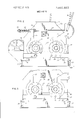
FIG. 1 is a perspective view of a flaking mill embodying my invention;
FIG. 2 is a side-elevation view of the mill of FIG. 1;
FIG. 3 is a side elevation similar to FIG. 2 with the roll tensioning assembly removed;
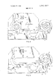
FIG. 4 is a side elevation as in FIG. 3 with the front roll in position outside the mill housing;
FIG. 5 is aside elevation view similar to FIG. 4 with both rolls removed;
FIG. 6 is a front elevation of the mill in the position of FIG. 4;
FIG. 7 is an enlarged side elevation of a part of the mill as shown in FIGS. 4 and 6;
FIG. 8 is a top plan view of the part of FIG. 7;
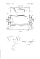
FIG. 9 is a side elevation of the mill on the side opposite that of FIG. 2; and,
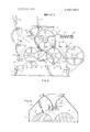
FIG. 10 is a partial sectional elevation view taken along the line 10-10 of FIG. 6.
Referring now to the drawings, the roll mill illustrated in FIGS. 1 and 2 comprises a housing 10 of generally rectangular configuration and including side walls, one of which is indicated at 11 and front and rear walls, the front wall being indicated at 12. The side walls extend upwardly to an attaching flange 13 and the front and rear walls are sloped toward the flange as indicated at 12a and 14. When the mill as illustrated in FIGS. 1 and 2 is installed for operation the steaming chamber (not shown) for steaming the grain and facilitating the flaking thereof is mounted on top of the housing 10 in engagement with the flange 13. The heavy duty dual roll mill comprises front and rear mill rolls mounted on shafts l5 and 16, respectively, the shafts being carried in front and rear bearing assemblies 17 and 18, respectively. The rollers are carried on the walls of the housing and longitudinal structural members 20 are provided for facilitating the mounting of the bearing assemblies in position.
The bearing assemblies 17 and 18 are carried in bearing retainer arms 21 and 22 respectively, these arms being pivotally mounted on the housing on bolts or pins 23 and 24 which are securely mounted in the supporting structure includingthe member 20 and a longitudinal reinforcing member 25 which is suitably secured to the housing wall by welding or bolting or otherwise. The bearing assembly 17 is held rigidly in position by additional bolts 26 and 27 secured in a longitudinal members 20 and 25 after the retainer arm 21 is in position in engagement with the assembly 17.
The bearing assemblies 17 and 18 have cylindrical body portions, this portion of the assembly 18 is indicated at 19 in FIG. 1. These assemblies include inner plates 17b and 18b, respectively and outer plates 17c and 180, respectively. The inner and outer plates of the assembly 17 and 18 are secured together against the respective cylindrical body portions by sets of six bolts 29 and 30, respectively. The cylindrical portions fit in circular or cylindrical seats in the arms 17 and 18; these seats are shown at 21a and 22a in FIG. 5. When installed on the retainer arms three of the bolts of each set pass through the arm to secure the bearing assemblies rigidly in position on their respective arms. These three bolts are removed when the mill rolls are to be moved out of the housing for servicing and the bearing assemblies must be released from the retainer arms.
When securing the retainer arms 21 and 22 in position to hold the rolls in operating relationship, the arms 21 are first moved into their upright positions and bolted therein and the bearing assemblies are bolted to the arms. The front and rear arms 21 and 22 are then clamped in position by the tension bars 28, one on either side of the housing, and which are attached to the retainer arms 21 and 22 at their upper ends. The arms are drawn together by operation of handle 31 which apply tension to the rods 28 against the pressure of compression springs 32 mounted on the far side of the retaining arm 22 and of the retainer 21 and which may be adjusted by nuts 33. Inspection doors are provided in the front wall 12 in the lower portion of the front wall indicated at 34 and another in an inclined portion 12a in the front wall indicated at 35.
Scraper bars (not shown) are provided within the housing 10 below the rolls for clearing the product from the rolls. These bars may be adjusted by pivoted arms 36 by moving the positions of these arms with respect to pivoted or swinging posts 37. A suitable feed roll and flow control described below is provided in the path of the grain supplied to the rollers and is driven by a feed roll drive shaft 38. The drive shaft 38 and the shafts l5 and 16 are connected to be driven by suitable motor or engine (not shown) through the shaft 15 which extends outwardly a substantial distance and has a keyway for securing a drive pulley or coupling (not shown). A suitable reversing drive such as a serpentine double V-Belt or reversing sheave drive as described below is provided on the opposite side for driving the rolls in opposite directions of rotation.
During the operation of the mill when roll replacement repair or servicing is required it has heretofore been necessary to dismantle the mill structure in order to gain access to the rolls so that they may be lifted out of their positions therein. In order to avoid long shutdown periods during servicing, repair or replacement, the present invention provides an improved arrangement whereby the rolls may be moved out from the housing without dismantling the grain feed control, the steaming chamber or other equipment mounted on the housing and without dismantling the housing. For this purpose the housing frame members including the members have been constructed and arranged so that the rolls may be moved outwardly along side wall portions as tracks and may be removed through a front door or panel 40 which is detachable and removable. The door 40 is provided with handles or hooks 41 by which the door may be lifted and moved aside. When it is desired to remove the rolls, the tension rigging including the tension bars 28 and the mounting assemblies for the handle 31 are removed whereupon the mill appears as shown in FIG. 3. Bolts 26 and 27 are then removed and the bearing retainer arm 21 is rotated clockwise downwardly to a position as shown in FIG. 4. An enclosure plate 42 mounted in the front portion of a slot 43 extending longitudinally of the housing and opening toward the front is removed and a track extension member comprising an upright column 44 and a transverse member 45 is attached to the outer end of the arm 21 by bolts 46 which extend through holes also used for attaching the assembly for the handle 31. The horizontal member 45 when positioned with the arm 21 in its bottom position lies with its top edge constituting a continuation of the horizontal structural member or track 20 and this provides an extended track along which the front roll, indicated at 17a, may be rolled out with the bearing assemblies remaining in place thereon at both ends. It will be understood that the arms 21 and 22 have counterparts on the opposite side of the housing for retaining the bearing assemblies on the opposite side of the housing and that the reinforcing plates 20 and slot 43 are also duplicated on the opposite wall of the housing. The bearing assemblies and their positions on the housing also can be seen in FIG. 6 which is a front view of the housing with the door 40 removed as shown in FIG. 4. The closure plates 42 are securely attached in any suitable manner to the housing wall and provide an opening adjacent the bearing assemblies when in position which is somewhat elongated and affords slight movement of the rolls therein. However, the bearing assembly also closes the opening adjacent the assembly so that the housing is effectively closed when the plate is in position. A second plate 47 is provided between the two bearing assemblies and closes the central portion of the slot 43. After this plate has been detached from its position in the slot 43, the second roll, indicated at 18a, may be rolled out along the tracks indicated at 43a and which are provided by the bottom edges of the slot 43, and then along the extension 45. As shown in FIGS. 4 and 5, when the retainer arm is in its down position its end rests against a flange 48 of the base of the housing and when in this position locates the track 45 in alignment with the horizontal slot track 43a.
During normal operation of the rolls the shaft and bearing assemblies are out of Contact with the track 20, a slight lifting of the assemblies from the track being effected by rotating or arcuate movement of the arms 21 and 22 into their upright positions. The rolls are lowered into engagement with the tracks upon release of the tension rods 28 which allows the arms 21 and 22 to rotate out of their upright positions. The front roll on the shaft 15 may be removed from the track 46 and the second roll moved forward along the track 43a to the track 46 for similar removal. It will thus be seen that heavy rollers which may have weights of the order of 2,000 pounds each may thus be moved out from the mill housing without disturbing any of the structure above the rollers, and dismantling of the mill is therefore not necessary for roll servicing purposes.
When the rolls 17a and 18a are to be returned to their operating positions, the rear roll 18a is first placed upon the extended track and is rolled back into position, the arms 22 being brought up to receive the bearing assemblies 18 which are then bolted to the assemblies by three of the bolts 30. Plates 47 are then returned to their positions in the slot 43 and are secured to the housing wall, and the front roller 17a is placed on the tracks and rolled back into position along the horizontal slot tracks 43a. The track extension members 44 are then removed from the arms 21 and the arms are rotated upwardly into position about the bearing assemblies and are pressed to their upright positions thus lifting the roll 17a. Bolts 26 and 27 as well as the three bolts 29 are secured to firmly attach the retaining arms 21 to the bearing assemblies and in their operating positions. The tension assembly is then re-installed and the arms are drawn together to bring the bearing assemblies 18 also into their required slightly raised operating positions wherein the roll 18 is free from enagagement with the horizontal slot track 43a.
The end view, FIG. 6, shows the roller 17a in the same position on the end supports 45 as shown in FIG. 4. The shaft 15 includes the left hand extension for coupling to the driving motor and carries the bearing assembly 17 in position adjacent the housing 10. The shaft 15 has enlarged portions which rest on the tracks formed by the edge of the housing adjacent the horizontal slots 43. It is this portion 50 which rides on the housing track 43a and then moves out onto the track extension 45 on which the roll is resting in FIG. 6. The tension riggings including the bars 28 and the driving mechanism for rotating the rolls in opposite directions do not appear in FIG. 6 because these parts of the mill have been removed for the purpose of removing the rolls.
The mechanism for rotating the two rolls 17a and 18a in opposite directions and for driving the feed roll is shown in FIG. 9. The so-called serpintine drive for effecting opposite rotation of the two rolls includes a V-belt drive pulley wheel 51 mounted on a reduced shaft portion 52 which is an extension of the shaft 15. A second pulley of the same size is indicated at 53 which is secured on an extended shaft portion 54 of the shaft 16 and an idler pulley 55 is mounted on a support shelf at the back of the mill. A double V-belt 56 extends around the pulleys 51 and 55 on their top sides and then is reversed over the pulley 53 so that this pulley is driven in the opposite direction from pulleys 51 and 55. The direction of rotation of the pulley 51 and hence the roll 17a is clockwise as viewed in FIG. 9 and that of the pulley 53 counterclockwise.
A feed roll not shown in FIG. 9 is utilized to facilitate the movement of the grain or other material toward the feed zone between the rollers 17a and 18a and is driven by a pulley 57, which in turn is driven by a belt 58 extending about the pulley 57 and about a small drive pulley (not shown) on the shaft 54. The pulley 57 is thus driven in a counterclockwise direction as viewed in FIG. 9. Within the sloping upper portion of the housing there is arranged an adjustable feed control which cooperates with the feed roller to determine the rate of feed to the rolls. This control is actuated by a lever 60 movable along a curved guide 62 to effect a change in the cross section of the supply passage for the grain. A
- suitable lock indicated at 62 is slidable into position to lock the lever 60 in any selected position along the guide 61.
The adjustable control for regulating the rate of feed to the rolls is illustrated in FIG. 10. This control includes a flexible resilient metal sheet or baffle 63 which is of generally cylindrical configuration with its convex side upward toward the top of the housing. The lower portion of the sheet 63 is arranged to move toward and away from the feed roll indicated at 64 which, preferably is grooved or fluted longitudinally and may be spiraled. The grain supply chute is completed by the side walls of the housing and a baffle 65 rigidly secured to the housing and extending from the upper right hand corner of the housing at the top downwardly to a position adjacent the roll 64 it being slightly spaced from the roll to prevent frictional engagement. This baffle is also of generally cylindrical curvature with its convex side up. The baffles 63 and 65 have reinforcing flanges, 63a and 65a, respectively, along their lower edges.
The flexible sheet 63 is securely anchored to the upper left hand comer of the housing as viewed in FIG. 10 where it is welded or otherwise suitably attached rigidly to the housing structure. The main portion of the sheet is free to flex and is held in a position such that it is biased by its own resilience toward the roller 64. The lever 60 is connected to a shaft 66 on which are eccentrically mounted a plurality of cylinders 67 at spaced intervals along the shaft 66. A rectangular guide box or frame 68 is attached to the flexible sheet 63 adjacent each cylinder and has an internal passage of the same width as the diameter of the cylinder 67, so that when the cylinder is turned the sheet 63 is flexed either toward or away from the roll 64 and changes the spacing between the sheet 63 and the roll 64, thereby changing the opening through which the grain is supplied and controlling the rate of flow of grain. It will be observed that the sheet 63 may move slightly with respect to the cylinder 67 because the guide 68 does not restrain the sheet in the vertical direction. The sheet 63 positioned as shown provides a substantially vertical lower portion adjacent the roll 64 so that the passage through which the grain flows to reach the rolls is substantially vertical where the grain moves through the opening between the sheet 63 and the roller 64 from which the grain falls vertically to the line of engagement of the rolls, this zone being called the knip or bite.
During the operation of the feed control, the passage of the grain induced by gravity and by the rotation of the feed roller and the resulting driving effect on the grain a downward force is transmitted to sheet 63. This downward force produces a slight vertical up or down movement of the flexing sheet and facilitates the passage of grain through the opening between the feed roll and the sheet and results in a more uniform rate of feed of the grain. It has also been observed that the feed passage along the roll 64 tends to clear itself of any bridging of the grain between the roll 64 and the sheet 63. The curvature of the sheets 63 and 65 working in conjunction'with the movement 'of the jfeed roll appear to enhance this effect. A
The. sheet 63 providesa simple and very effective arrangement for controlling the flow of feed and makes it possible to use a relatively small area of the housing for the flow control mechanism. Furthermore, particularly in view of the manner in which the flow is directed toward the knip or zone of entrance or contact of the rolls, the feed control may easily be positioned above the top plane of the rolls so that the rolls are free to move out of. the housing without interference with the control mechanism which thus can remainin place during servicing of the rolls. This construction requires a minimum of moving parts, the flexible sheet 63 making it possible to eliminate hinged gates or similar valving arrangements. Improved operation and ease of control by manipulation of the lever is thus effected.
While the invention has been described in connection with a specific form of flaker mill, other applications and embodiments will occur to those skilled in the art. I therefore intend by the appended claims to cover all modifications which fall within the spirit and the scope of the invention.
I claim:
1. A dual roll mill for flaking grain or the like comprising:
a housing having front, rear and side walls;
the side walls of said housing having horizontal slots opening toward the front wall thereof;
a pair of mill rolls having shafts extending from the ends thereof;
roll supporting structure adjacent said slots;
means for mounting said rolls in said housing with the shafts thereof extending through said slots, said means including bearing assemblies for said shafts and releasable means for locking said bearing assemblies in position on said supporting structure; detachable means for closing said slots;
removable closure means at one end of said housing for affording when removed an open passage for said rolls; and,
means providing tracks adjacent the lower sides of said slots for affording rolling movement of said roll shafts whereby upon removal of said locking means and said slot closing means and said front wall closure means said rolls may be rolled forward and out through said front wall.
2. A dual roll mill for flaking grain or the like as set forth in claim 1 wherein said housing includes a base structure and said releasable bearing locking means includes structural members rotatably mounted adjacent the front ends of said side walls and movable from positions engaging the bearings of the front one of said rollers to positions engaging said base structure whereby the rolls may be rolled freely out of said slots.
3. A dual roll mill for flaking grain or the like as set forth in claim 2 including detachable means on said structural member for providing an extension of said tracks for supporting either of said rolls during movement out of said housing after removal of said front wall closure.
4. A dual roll mill for flaking grain or the like as set forth in claim 1 including front and rear bearing supports pivotally mounted on said frame on each side thereof for holding said shafts out of engagement with said tracks in one position and rotatable away from one another for lowering said shafts to said tracks upon rotation from said one position, and means for urging the front and rear bearing support toward one another.
5. A dual roll mill for flaking grain or the like as set forth in claim 4 wherein said shafts engaging said tracks between respective ends of said rolls and said bearing assemblies.
6. A dual roll mill for flaking grain and the like as set forth in claim 1 including a grain feed control assembly mounted in said housing directly above the adjacent faces of said rolls, said assembly comprising:
a grain chute, one wall of which is a cylindrical flexible metal sheet extending across said housing and having its upper face convex;
said sheet being rigidly secured to said housing along its upper edge and curving downwardly toward the lower end of said chute;
said chute terminating above said rolls a sufficient distance to afiord clearing said rolls when they are rolled from said housing; and,
feed adjusting means comprising a camming mechanism for flexing said sheet from a position of maximum feed to a position of minimum feed, said sheet being biased toward said maximum feed position.
7. A dual roll mill for flaking grain and the like as set forth in claim 6 wherein said chute includes a feeder roll mounted along the lower edge of said sheet for moving the grain downwardly toward the bite of said mill rolls.
8. A dual roll mill for flaking grain and the like as set forth in claim 7 wherein the lower curved portion of said sheet presents a substantially vertical wall throughout the range of adjustment of the positions of said sheet.
Claims (8)
1. A dual roll mill for flaking grain or the like comprising: a housing having front, rear and side walls; the side walls of said housing having horizontal slots opening toward the front wall thereof; a pair of mill rolls having shafts extending from the ends thereof; roll supporting structure adjacent said slots; means for mounting said rolls in said housing with the shafts thereof extending through said slots, said means including bearing assemblies for said shafts and releasable means for locking said bearing assemblies in position on said supporting structure; detachable means for closing said slots; removable closure means at one end of said housing for affording when removed an open passage for said rolls; and, means providing tracks adjacent the lower sides of said slots for affording rolling movement of said roll shafts whereby upon removal of said locking means and said slot closing means and said front wall closure means said rolls may be rolled forward and out through said front wall.
2. A dual roll mill for flaking grain or the like as set forth in claim 1 wherein said housing includes a base structure and said releasable bearing locking means includes structural members rotatably mounted adjacent the front ends of said side walls and movable from positions engaging the bearings of the front one of said rollers to positions engaging said base structure whereby the rolls may be rolled freely out of said slots.
3. A dual roll mill for flaking grain or the like as set forth in claim 2 including detachable means on said structural member for providing an extension of said tracks for supporting either of said rolls during movement out of said housing after removal of said front wall closure.
4. A dual roll mill for flaking grain or the like as set forth in claim 1 including front and rear bearing supports pivotally mounted on said frame on each side thereof for holding said shafts out of engagement with said tracks in one position and rotatable away from one another for lowering said shafts to said tracks upon rotation from said one position, and means for urging the front and rear bearing support toward one another.
5. A dual roll mill for flaking grain or the like as set forth in claim 4 wherein said shafts engaging said tracks between respective ends of said rolls and said bearing assemblies.
6. A dual roll mill for flaking grain and the like as set forth in claim 1 including a grain feed control assembly mounted in said housing directly above the adjacent faces of said rolls, said assembly comprising: a grain chute, one wall of which is a cylindrical flexible metal sheet extending across said housing and having its upper face convex; said sheet being rigidly secured to said housing along its upper edge and curving downwardly toward the lower end of said chute; said chute terminating above said rolls a sufficient distance to afford clearing said rolls when they are rolled from said housing; and, feed adjusting means comprising a camming mechanism for flexing said sheet from a position of maximum feed to a position of minimum feed, said sheet being biased toward said maximum feed position.
7. A dual roll mill for flaking grain and the like as set forth in claim 6 wherein said chute includes a feeder roll mounted along the lower edge of said sheet for moving the grain downwardly toward the bite of said mill rolls.
8. A dual roll mill for flaking grain and the like as set forth in claim 7 wherein the lower curved portion of said sheet presents a substantially vertical wall throughout the range of adjustment of the positions of said sheet.
Priority Applications (1)
| Application Number | Priority Date | Filing Date | Title |
|---|---|---|---|
| US442462A US3881663A (en) | 1974-02-14 | 1974-02-14 | Roll mill for flaking grain and the like |
Applications Claiming Priority (1)
| Application Number | Priority Date | Filing Date | Title |
|---|---|---|---|
| US442462A US3881663A (en) | 1974-02-14 | 1974-02-14 | Roll mill for flaking grain and the like |
Publications (1)
| Publication Number | Publication Date |
|---|---|
| US3881663A true US3881663A (en) | 1975-05-06 |
Family
ID=23756873
Family Applications (1)
| Application Number | Title | Priority Date | Filing Date |
|---|---|---|---|
| US442462A Expired - Lifetime US3881663A (en) | 1974-02-14 | 1974-02-14 | Roll mill for flaking grain and the like |
Country Status (1)
| Country | Link |
|---|---|
| US (1) | US3881663A (en) |
Cited By (29)
| Publication number | Priority date | Publication date | Assignee | Title |
|---|---|---|---|---|
| US3970256A (en) * | 1974-01-18 | 1976-07-20 | Buhler Ag | Grinding mill |
| US4047673A (en) * | 1975-04-12 | 1977-09-13 | Aulmann & Beckschulte | Single-roll crusher |
| US4423844A (en) | 1981-10-02 | 1984-01-03 | Triple/S Dynamics, Inc. | Apparatus for shredding materials |
| EP0124872A3 (en) * | 1983-05-06 | 1986-02-05 | GOLFETTO S.p.A. | Roller mill of the horizontal roll type for cereals |
| US4630781A (en) * | 1984-07-11 | 1986-12-23 | T.J. Gundlach Machine Company | Apparatus and method for removing crushing rolls from a crushing apparatus |
| EP0212882A3 (en) * | 1985-08-07 | 1988-04-27 | Wolverine Corporation | cereal flaking mill |
| WO1993013857A1 (en) * | 1992-01-20 | 1993-07-22 | Golfetto S.P.A. | Roller mill for cereals |
| US5566902A (en) * | 1995-05-12 | 1996-10-22 | California Pellet Mill Company | Roll arrangement for a milling machine, and an inter-roll drive therefor |
| US5609308A (en) * | 1995-10-16 | 1997-03-11 | California Pellet Mill Company | Fine adjustment/quick acting manual actuator for roller mill feed gates |
| US5823452A (en) * | 1997-05-05 | 1998-10-20 | Ballew; Russell | Flaker mill |
| US6129296A (en) * | 1999-06-08 | 2000-10-10 | Poarch Bros. Inc. | Double roll peg feeder assembly for flaking mills |
| USD549747S1 (en) * | 2005-04-21 | 2007-08-28 | Satake Corporation | Roll mill |
| USD552134S1 (en) * | 2005-04-21 | 2007-10-02 | Satake Corporation | Roll mill |
| US20080073454A1 (en) * | 2006-09-25 | 2008-03-27 | Yu-Chao Chao | Housing for high-speed rotational wood chopping cutter |
| USD612873S1 (en) * | 2009-03-06 | 2010-03-30 | Wieland Dental & Technik Gmbh & Co. Kg | Milling machine |
| US20100090044A1 (en) * | 2008-09-29 | 2010-04-15 | Hartmut Pallmann | Device for processing feedstock |
| US20120266581A1 (en) * | 2009-10-09 | 2012-10-25 | Agco Gmbh | Compression Roll Housing |
| US20130298373A1 (en) * | 2012-05-11 | 2013-11-14 | Metso Minerals Industries, Inc. | Handling apparatus and methods for handling a roller of a roller crusher |
| USD706320S1 (en) * | 2014-01-31 | 2014-06-03 | Zapadoceska Univerzita V Plzni | Milling machine |
| CN103919254A (en) * | 2014-04-30 | 2014-07-16 | 山东泗水冠峰粮食机械有限公司 | Constant-distance and constant-pressure cereal sheet rolling machine |
| CN105413802A (en) * | 2015-12-27 | 2016-03-23 | 刘汉佑 | Food pulverizing device |
| WO2016115229A1 (en) * | 2015-01-16 | 2016-07-21 | Flsmidth A/S | Extraction mechanism for a comminution device |
| USD765155S1 (en) * | 2014-09-12 | 2016-08-30 | Bühler AG | Roller mill |
| DE102012009590C5 (en) * | 2012-05-11 | 2016-09-22 | Envipco Holding N.V. | Compacting device for empties |
| US20160339441A1 (en) * | 2015-05-21 | 2016-11-24 | Takraf Gmbh | Machinery frame for a roller crusher |
| CN107309023A (en) * | 2017-07-24 | 2017-11-03 | 安徽省禾健米业集团有限公司 | A kind of grain high-efficiency grinding system |
| CN107413444A (en) * | 2017-07-25 | 2017-12-01 | 安徽省禾健米业集团有限公司 | A kind of grain processing metering system |
| USD924947S1 (en) * | 2018-05-28 | 2021-07-13 | Bühler AG | Roller mill for grain milling |
| USD1065272S1 (en) * | 2024-02-05 | 2025-03-04 | Achenbach Buschhütten GmbH & Co. KG | Rolling mill for metal |
Citations (6)
| Publication number | Priority date | Publication date | Assignee | Title |
|---|---|---|---|---|
| US447765A (en) * | 1891-03-10 | Roller-mill | ||
| US1042923A (en) * | 1912-05-16 | 1912-10-29 | William O Kaiser | Ointment-machine. |
| US1199938A (en) * | 1913-04-26 | 1916-10-03 | Sprout Waldron & Company | Roller-mill. |
| US1823437A (en) * | 1928-02-22 | 1931-09-15 | Cooper Dhanjishah Bomonjee | Crushing machine |
| US2135174A (en) * | 1931-06-12 | 1938-11-01 | Cox Henry Edward | Roller and roller and breast mills |
| US3220658A (en) * | 1961-12-18 | 1965-11-30 | Gruendler Crusher & Pulverizer | Hammermills |
-
1974
- 1974-02-14 US US442462A patent/US3881663A/en not_active Expired - Lifetime
Patent Citations (6)
| Publication number | Priority date | Publication date | Assignee | Title |
|---|---|---|---|---|
| US447765A (en) * | 1891-03-10 | Roller-mill | ||
| US1042923A (en) * | 1912-05-16 | 1912-10-29 | William O Kaiser | Ointment-machine. |
| US1199938A (en) * | 1913-04-26 | 1916-10-03 | Sprout Waldron & Company | Roller-mill. |
| US1823437A (en) * | 1928-02-22 | 1931-09-15 | Cooper Dhanjishah Bomonjee | Crushing machine |
| US2135174A (en) * | 1931-06-12 | 1938-11-01 | Cox Henry Edward | Roller and roller and breast mills |
| US3220658A (en) * | 1961-12-18 | 1965-11-30 | Gruendler Crusher & Pulverizer | Hammermills |
Cited By (38)
| Publication number | Priority date | Publication date | Assignee | Title |
|---|---|---|---|---|
| US3970256A (en) * | 1974-01-18 | 1976-07-20 | Buhler Ag | Grinding mill |
| US4047673A (en) * | 1975-04-12 | 1977-09-13 | Aulmann & Beckschulte | Single-roll crusher |
| US4423844A (en) | 1981-10-02 | 1984-01-03 | Triple/S Dynamics, Inc. | Apparatus for shredding materials |
| EP0124872A3 (en) * | 1983-05-06 | 1986-02-05 | GOLFETTO S.p.A. | Roller mill of the horizontal roll type for cereals |
| US4630781A (en) * | 1984-07-11 | 1986-12-23 | T.J. Gundlach Machine Company | Apparatus and method for removing crushing rolls from a crushing apparatus |
| EP0212882A3 (en) * | 1985-08-07 | 1988-04-27 | Wolverine Corporation | cereal flaking mill |
| WO1993013857A1 (en) * | 1992-01-20 | 1993-07-22 | Golfetto S.P.A. | Roller mill for cereals |
| US5566902A (en) * | 1995-05-12 | 1996-10-22 | California Pellet Mill Company | Roll arrangement for a milling machine, and an inter-roll drive therefor |
| US5609308A (en) * | 1995-10-16 | 1997-03-11 | California Pellet Mill Company | Fine adjustment/quick acting manual actuator for roller mill feed gates |
| US5823452A (en) * | 1997-05-05 | 1998-10-20 | Ballew; Russell | Flaker mill |
| US6129296A (en) * | 1999-06-08 | 2000-10-10 | Poarch Bros. Inc. | Double roll peg feeder assembly for flaking mills |
| USD549747S1 (en) * | 2005-04-21 | 2007-08-28 | Satake Corporation | Roll mill |
| USD552134S1 (en) * | 2005-04-21 | 2007-10-02 | Satake Corporation | Roll mill |
| US20080073454A1 (en) * | 2006-09-25 | 2008-03-27 | Yu-Chao Chao | Housing for high-speed rotational wood chopping cutter |
| US20100090044A1 (en) * | 2008-09-29 | 2010-04-15 | Hartmut Pallmann | Device for processing feedstock |
| US8267341B2 (en) * | 2008-09-29 | 2012-09-18 | Pallmann Maschinenfabrik Gmbh & Co. Kg | Device for processing feedstock |
| USD612873S1 (en) * | 2009-03-06 | 2010-03-30 | Wieland Dental & Technik Gmbh & Co. Kg | Milling machine |
| US20120266581A1 (en) * | 2009-10-09 | 2012-10-25 | Agco Gmbh | Compression Roll Housing |
| US9192106B2 (en) * | 2009-10-09 | 2015-11-24 | Agco Gmbh | Compression roll housing |
| US20130298373A1 (en) * | 2012-05-11 | 2013-11-14 | Metso Minerals Industries, Inc. | Handling apparatus and methods for handling a roller of a roller crusher |
| US8973856B2 (en) * | 2012-05-11 | 2015-03-10 | Metso Minerals Industries, Inc. | Handling apparatus and methods for handling a roller of a roller crusher |
| DE102012009590C5 (en) * | 2012-05-11 | 2016-09-22 | Envipco Holding N.V. | Compacting device for empties |
| USD706320S1 (en) * | 2014-01-31 | 2014-06-03 | Zapadoceska Univerzita V Plzni | Milling machine |
| CN103919254A (en) * | 2014-04-30 | 2014-07-16 | 山东泗水冠峰粮食机械有限公司 | Constant-distance and constant-pressure cereal sheet rolling machine |
| USD765155S1 (en) * | 2014-09-12 | 2016-08-30 | Bühler AG | Roller mill |
| US10232380B2 (en) | 2015-01-16 | 2019-03-19 | Flsmidth A/S | Extraction mechanism for comminution device |
| WO2016115229A1 (en) * | 2015-01-16 | 2016-07-21 | Flsmidth A/S | Extraction mechanism for a comminution device |
| US20160339441A1 (en) * | 2015-05-21 | 2016-11-24 | Takraf Gmbh | Machinery frame for a roller crusher |
| US10307764B2 (en) * | 2015-05-21 | 2019-06-04 | Takraf Gmbh | Machinery frame for a roller crusher |
| CN105413802A (en) * | 2015-12-27 | 2016-03-23 | 刘汉佑 | Food pulverizing device |
| CN107309023A (en) * | 2017-07-24 | 2017-11-03 | 安徽省禾健米业集团有限公司 | A kind of grain high-efficiency grinding system |
| CN107413444A (en) * | 2017-07-25 | 2017-12-01 | 安徽省禾健米业集团有限公司 | A kind of grain processing metering system |
| USD924947S1 (en) * | 2018-05-28 | 2021-07-13 | Bühler AG | Roller mill for grain milling |
| USD934928S1 (en) | 2018-05-28 | 2021-11-02 | Bühler AG | Roller mill for grain milling |
| USD941896S1 (en) | 2018-05-28 | 2022-01-25 | Bühler AG | Top box for grain milling |
| USD1065272S1 (en) * | 2024-02-05 | 2025-03-04 | Achenbach Buschhütten GmbH & Co. KG | Rolling mill for metal |
| USD1089332S1 (en) * | 2024-02-05 | 2025-08-19 | Achenbach Buschhütten GmbH & Co. KG | Rolling mill for metal |
| USD1089333S1 (en) * | 2024-02-05 | 2025-08-19 | Achenbach Buschhütten GmbH & Co. KG | Rolling mill for metal |
Similar Documents
| Publication | Publication Date | Title |
|---|---|---|
| US3881663A (en) | Roll mill for flaking grain and the like | |
| US6685118B1 (en) | Two roll crusher and method of roller adjustment | |
| US4948017A (en) | Rotary feeder | |
| AU2008274475B2 (en) | Roller press with retractable grinding material guide metal sheet | |
| US2429142A (en) | Roller leveler machine | |
| CA2179121C (en) | Bale shredder | |
| US4630781A (en) | Apparatus and method for removing crushing rolls from a crushing apparatus | |
| JP2005225677A (en) | Roller retainer and conveyor equipped with retainer | |
| CA2101481C (en) | Combination cobble cover and guide trough for rolling mill | |
| US3174696A (en) | Roller mill | |
| US3525517A (en) | Sheet feeding apparatus | |
| US3222901A (en) | Rolling mill | |
| US5461763A (en) | Curtain apparatus | |
| US4640338A (en) | Roller apron for casting of support-pre-profiles or sectional shapes and blooms in a continuous casting installation | |
| US3818567A (en) | Apparatus for positioning journal assemblies in pulverizers | |
| US3229805A (en) | Magnetic rail conveyor | |
| US5640747A (en) | Curtain apparatus | |
| US4577672A (en) | Device for manufacturing metal strip | |
| US2771249A (en) | Slide track mounting means for different mesh size screens in screening mills | |
| CN86104686A (en) | Apparatus and method for removing crushing rolls from a crushing plant | |
| CN220277875U (en) | Multifunctional waste box suitable for high-speed rolling | |
| US1257691A (en) | Machine for grinding dies. | |
| JPS58116902A (en) | Equipment that can selectively or sequentially perform temper rolling and straightening of workpiece materials | |
| CN219073069U (en) | Anti-blocking discharging mechanism | |
| CN213010510U (en) | A barrel cover shunt conveying device |