US3880446A - Hydropneumatic suspension for land vehicles especially tracked vehicles - Google Patents
Hydropneumatic suspension for land vehicles especially tracked vehicles Download PDFInfo
- Publication number
- US3880446A US3880446A US414828A US41482873A US3880446A US 3880446 A US3880446 A US 3880446A US 414828 A US414828 A US 414828A US 41482873 A US41482873 A US 41482873A US 3880446 A US3880446 A US 3880446A
- Authority
- US
- United States
- Prior art keywords
- gas cushion
- control piston
- main gas
- valve
- cushion
- Prior art date
- Legal status (The legal status is an assumption and is not a legal conclusion. Google has not performed a legal analysis and makes no representation as to the accuracy of the status listed.)
- Expired - Lifetime
Links
- 239000000725 suspension Substances 0.000 title claims abstract description 45
- 230000008602 contraction Effects 0.000 claims description 16
- 239000012530 fluid Substances 0.000 claims description 12
- 238000006073 displacement reaction Methods 0.000 claims description 7
- 238000007906 compression Methods 0.000 abstract description 5
- 230000009466 transformation Effects 0.000 abstract description 2
- 230000010355 oscillation Effects 0.000 description 17
- 238000013016 damping Methods 0.000 description 10
- 239000007788 liquid Substances 0.000 description 8
- 230000035939 shock Effects 0.000 description 6
- 239000012528 membrane Substances 0.000 description 5
- 239000006096 absorbing agent Substances 0.000 description 4
- 230000006835 compression Effects 0.000 description 4
- 239000011324 bead Substances 0.000 description 2
- 230000015556 catabolic process Effects 0.000 description 2
- 238000010276 construction Methods 0.000 description 2
- 208000036366 Sensation of pressure Diseases 0.000 description 1
- 230000000903 blocking effect Effects 0.000 description 1
- 239000003795 chemical substances by application Substances 0.000 description 1
- 238000004891 communication Methods 0.000 description 1
- 239000002826 coolant Substances 0.000 description 1
- 230000001934 delay Effects 0.000 description 1
- 230000001419 dependent effect Effects 0.000 description 1
- 230000001788 irregular Effects 0.000 description 1
- 238000005192 partition Methods 0.000 description 1
- 230000000149 penetrating effect Effects 0.000 description 1
- 229920000136 polysorbate Polymers 0.000 description 1
- 230000001737 promoting effect Effects 0.000 description 1
- 230000003068 static effect Effects 0.000 description 1
Images

Classifications
-
- B—PERFORMING OPERATIONS; TRANSPORTING
- B62—LAND VEHICLES FOR TRAVELLING OTHERWISE THAN ON RAILS
- B62D—MOTOR VEHICLES; TRAILERS
- B62D55/00—Endless track vehicles
- B62D55/08—Endless track units; Parts thereof
- B62D55/104—Suspension devices for wheels, rollers, bogies or frames
- B62D55/112—Suspension devices for wheels, rollers, bogies or frames with fluid springs, e.g. hydraulic pneumatic
- B62D55/1125—Hydro-pneumatic or pneumatic, e.g. air-cushioned
-
- B—PERFORMING OPERATIONS; TRANSPORTING
- B60—VEHICLES IN GENERAL
- B60G—VEHICLE SUSPENSION ARRANGEMENTS
- B60G11/00—Resilient suspensions characterised by arrangement, location or kind of springs
- B60G11/26—Resilient suspensions characterised by arrangement, location or kind of springs having fluid springs only, e.g. hydropneumatic springs
- B60G11/30—Resilient suspensions characterised by arrangement, location or kind of springs having fluid springs only, e.g. hydropneumatic springs having pressure fluid accumulator therefor, e.g. accumulator arranged in vehicle frame
-
- F—MECHANICAL ENGINEERING; LIGHTING; HEATING; WEAPONS; BLASTING
- F16—ENGINEERING ELEMENTS AND UNITS; GENERAL MEASURES FOR PRODUCING AND MAINTAINING EFFECTIVE FUNCTIONING OF MACHINES OR INSTALLATIONS; THERMAL INSULATION IN GENERAL
- F16F—SPRINGS; SHOCK-ABSORBERS; MEANS FOR DAMPING VIBRATION
- F16F9/00—Springs, vibration-dampers, shock-absorbers, or similarly-constructed movement-dampers using a fluid or the equivalent as damping medium
- F16F9/06—Springs, vibration-dampers, shock-absorbers, or similarly-constructed movement-dampers using a fluid or the equivalent as damping medium using both gas and liquid
- F16F9/08—Springs, vibration-dampers, shock-absorbers, or similarly-constructed movement-dampers using a fluid or the equivalent as damping medium using both gas and liquid where gas is in a chamber with a flexible wall
- F16F9/081—Springs, vibration-dampers, shock-absorbers, or similarly-constructed movement-dampers using a fluid or the equivalent as damping medium using both gas and liquid where gas is in a chamber with a flexible wall being of the fluid displacement type, i.e. the piston not comprising damping arrangements
Definitions
- a second pressurizable gas chamber is provided and is connected to the primary gascompression chamber by a valve operated with a predetermined lag or delay so that the energy generated by movement of the suspended part toward the chassis or body of the vehicle is stored and supplied to the suspended part at a subsequent time without substantial transformation of the suspension energy into heat or other dissipation of this energy.
- My present invention relates to vehicle suspensions and especially suspensions for land vehicles of the tracked type, eg tanks, earth movers and cranes. More particularly, the invention relates to a suspension system having means for storing and releasing the suspension energy.
- a motorvehicle suspension is disposed between the vehicle chassis or body and a suspended member such a vehicle wheel or axle and includes in addition to leaf, coil or torsion spring, one or more oscillation-damping or shock-absorbing members.
- the latter may comprise a piston displaceable in a cylinder and a throttle connecting two chambers and through which the hydraulic medium is displaced in a so-called dashpot.
- the oscillation energy of the suspended body is converted into kinetic energy of the liquid in the cylinder and eventually transformed into heat which is dissipated by the shock absorber.
- the oscillation damping member must be disposed between the body of the vehicle and a wheel capable of undergoing vertical displacement relative to the vehicle body.
- the displacement can be considered a contraction as the wheel moves toward the body and an expansion as the wheel moves away from the body.
- the shock energy produced during contraction is freed. in the absence of a damper, during expansion and results in oscillation of the vehicle body.
- the vehicle and its spring system thus form an oscillatable system whose characteristic frequency is dependent upon the vehicle mass and the spring constant.
- the oscillation system can reach a resonant state and yield abnormally high oscillation amplitudes.
- a second disadvantage of a conventional oscillation damping system of the character described is that the generated thermal energy rapidly produces breakdowns of the shock absorber, in the absence of special precautions to dissipate or eliminate the generated heat.
- the problem is multiplied by the fact that not only must the oscillation damping heat be eliminated, but the heat of the engine must be dissipated from the vehicle as well.
- Another object of this invention is to provide a longwearing, low cost and highly effective shock-damping or oscillation-damping system for a land vehicle, especially a tracked vehicle, in which the thermal drawbacks mentioned earlier do not arise.
- the present invention obviates the aforedescribed disadvantages by eliminating in large measure frictional dissipation of shock energy and by providing for the storage of the contraction energy (energy resulting from movement of the vehicle body and wheel toward one another) and release of this stored energy during an expansion phase but at times offset from the beginning of the contraction and expansions phases respectively.
- At least part of the oscillation energy which is generated in the hydropneumatic suspension is stored in a separate container and is supplied to the hydropneumatic suspension during a second (expansion) phase
- This storage and resupply of energy, in the form of compression of a gas other than the hydropneumatic suspension gas cushion, is effected by a valve.
- the system thus differs from the conventional damping system in which the oscillation energy is dissipated as heat by providing for compression and expansion of a gas out of phase with the beginning of the contraction and expansion phases respectively so that the oscillations are counteracted rather than dissipated.
- the contraction is counteracted by pressurizing a gas previously stored and a similar counteraction occurs during the expansion phase.
- the oscillation tendency is reduced by the supply or the withdrawal of energy in an out-of-phase relationship, to the vehicle oscillation mode.
- the valve is controlled automatically and in a simple manner by providing it between the pneumatic chamber of the hydropneumatic suspension and the auxiliary pneumatic accumulator and controlling the valve by a member responsive to fluid pressure and enabling the fluid pressure on one side of the member to respond rapidly while a throttle connects this side of the actuating member with the other side.
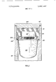
- FIG. 1 is a vertical cross-sectional view. partly in dia gramatic form of a suspension arrangement according to the invention.
- FIG. 2 is a partial sectional view of a modified suspension member.
- the suspension member illustrated in FIG. 1 comprises a housing 21 forming a main or primary gas accumulator or cushion 2, an auxiliary or secondary gas cushion or chamber 4 separated from the primary chamber 2 by a partition 23. and a liquid-filled space 1 disposed between a piston 5 and membrane 3 separating the hydraulic chamber 1 from the primary accumulator chamber 2.
- the piston 5 is provided with a flange-type seal 50 and is connected by a piston rod 6 with the suspended member. e.g. a wheel guiding the track of the vehicle.
- the housing 21 is attached to the vehicle body or chassis by conventional means. A clearance 60 around the piston rod 6 permits air to flow into and out of the space Zla between the piston 5 and the bottom wall 30 of the housing.
- valve assembly 7 which. in the manner to be described hereinafter, permits out-of-phase communication be tween the gas cushions.
- the blocking valve 7 comprises a valve plate 8 which bears against an annular valve set 80 around a bore 8b under the force of a helical compression spring 11 in a chamber 150 communicating by a passage 15 with the main gas cushion 2.
- the oppositely effective plate valve 9 bears against a valve seat 90 surrounding a bore 9b under the force of a helical coil spring 10 in a chamber 14a communicating with a passage 14 which opens into the storage cushion 4.
- the springs l0 and 11 are respectively seated against walls 7a and 7b of the valve assembly 7.
- the valve assembly 7 also includes a chamber 7c between the two valves 8 and 9 and in which a valvecontrol member 12 is provided.
- the control member 12 includes a pair of rod portions 120 and 12b respectively. and penetrating into the chambers a and 14a for engagement with the valve members 8 and 9.
- the valve member 12 is provided with a disk-like control piston 13 which subdivides the chamber 7c into a lower space 16 and an upper space 160. The space 160 communicates with passage 15 via an opening 16b.
- the fluid pressure from the main cushion 2 is applied by a passage 15 to the upper surface ofthe control piston l3, i.e. to the chamber 160.
- the control piston 13 has a diameter which is slightly less than the inner diameter of the cylindrical chamber to form a narrow throttle slit 17 around the periphery of this control piston.
- a controllable throttle may be provided between the chambers or opposite sides of the control piston.
- the chamber 7c is formed with a bore 18a into which a valve needle 18 may fit. the latter having a threaded shank 18b enabling the throttle to be adjusted by a screw head 181 from the exterior of the housing 21.
- the throttle means may be constituted by one or more bores provided directly in the piston 13.
- the membrane 3, which may be composed of rubber resistant to the hydraulic fluid. has a bead 24 which is received within an annular groove 25 formed in the housing 21 around the valve assembly 7.
- the piston 5 is shown in its normal (static) rest position. i.e. the suspension is neither contracted nor expanded. Should the vehicle be traveling along a terrain in which a hill or bump is encountered, the wheel or track roller will rise while inertia and gravitational forces acting upon the vehicle body limit the lifting thereof. The suspension thus undergoes contraction in which the piston 5 is displaced upwardly relative to the housing 21 to drive the liquid 1 (a hydraulic medium) in the same direction and compress the volume of the main gas cushion 2.
- the pressure rise is transmitted via passage 15 to the space 16a above the control piston 13. Because of the throttle l7 and/l8, the chamber 16 has lower pressure than that rapidly increasing in chamber I611.
- the pres' sure differential thus applied to the control piston 13 holds the latter downwardly and. via rod 12b maintains the valve 9 in a closed position. Only toward the end of the contraction stroke. at a time determined by the throttle cross section. is the control piston 12 able to be displaced away from its original position and the valve 9 able to open.
- the pressure buildup in cushion 2 is thus applied through the valve 9 and passage 14 to the auxiliary gas cushion 4.
- the pressure transfer thus results in a storage of energy during the contraction stroke in the gas cushion 4 which is not released during return of the piston 5 to its original position.
- the piston 5 moves in the opposite direction while the control piston 13 prevents opening of the valve body 8.
- the stored energy thus remains past the initial expan sion stage.
- the expansion causes the pressure in the chamber 2 to drop rapidly and thereby lowers the pressure in chamber while chamber 16 remains at an elevated pressure until equalization through the throttle l7 and/l8.
- the control piston 12 is held against the valve member 8 during this period.
- the valve 8 is opened to permit the stored pressure to flow via passage 15 into the main cushion 2.
- the adjustable throttle [8 ) enables the delay to be established over a very wide range as is necessary for the particular requirements of the vehicle.
- the throttle 18 can be provided with directional characteristics so that the delay during contraction differs from the delay during expansion.
- the pressure storage and reapplication of the stored pressure can be applied to prevent the development of a resonant oscillation condition without complex control means and without uncontrolled delays resulting from control trains and the like. This can be understood by the realization that with a sudden pressure increase in chamber 2, the equalization to compartment 16 occurs equally rapidly.
- the pneumatic energy transfer from the main cushion 2 to the auxiliary cushion 4 and vice versa is ef fected with minimum mass transfer.
- the valve assembly 7 can be provided with replaceable and interchangeable parts and has the advantage that it is of simple construction with few parts. Furthermore, while I prefer to construct the device as a single compact unit, the liquid space 1. the main gas cushion 2 and the storage gas cushion 4 can be made a separate unit with the valve assembly 7 disposed as still another unit in a conduit connecting the main gas cushion and the storage cushion.
- FIG. 2 shows an ambodiment of the invention in which the valve assembly 107 has the same construction as the valve assembly 7 previously described and in which it is formed integrally with the wall 123.
- the latter has a disk configuration and is externally threaded as shown in 123 so that it can be screwed into an internal thread of the pressure-storage chamber 104 to clamp the bead 124 of membrane 103 against a shoulder 125.
- the liquid chamber is provided at 101 below the membrane 103 and a cap 120, having an O- ring seal 122, is threaded into the top of the housing 121 to close the latter.
- the delay time can be adjusted by replacing the valve assembly 107 and providing in the interchangeable valve assembly throttles of different dimensions.
- a hydropneumatic suspension adapted to be interposed between a body member and a wheel member of a land vehicle. said suspension comprising:
- housing means forming a chamber containing a hydraulic medium connected to one of said members, and a displacement element in said chamber for displacing said medium and connected to the other member;
- valve assembly in said housing means directly interconnecting said main gas cushion and said storage gas cushion out of contact with said medium and effective to enable storage of pressure in said storage gas cushion upon pressurization of said main gas cushion and to feed pressure from said storage gas cushion to said main gas cushion upon relief of said main gas cushion, said assembly comprising at least one valve member interposed between said gas cushions, a control piston engageable with said valve member. means for applying the pressure of said main gas cushion to one side of said control piston and a throttle for controlled equalization of pressures on opposite sides of said control piston.
- valve assembly comprises a pair of oppositely effective spring-loaded valve members selectively displaceable respectively to permit flow of fluid from one of said cushions to the other cushion and vice versa
- control piston having a pair of rods selectively engageable with said valve members and extending in opposite directions from said control piston, said control piston and said throttle being so constructed and arranged that the valve member controlling the flow from said storage gas cushion to said main gas cushion is blocked upon expansion of said assembly and the valve member permitting fluid flow from said main gas cushion to said storage gas cushion is blocked upon contraction of said suspension.
- valve assembly includes a compartment receiving said control piston with an annular clearance at least in part forming said throttle.
- a hydropneumatic suspension adapted to be interposed between a body member and a wheel member of a land vehicle. said suspension comprising:
- valve assembly interconnecting said main gas cushion and said storage gas cushion and effective to enable storage of pressure in said storage gas cushion upon pressurization of said main gas cushion and to feed pressure from said storage gas cushion to said main gas cushion upon relief of said main gas cushion.
- said assembly comprising at least one valve member interposed between said gas cushions.
- a control piston engageable with said valve member, means for applying the pressure of said main gas cushion to one side of said control piston and a throttle for controlled equalization of pres sures on opposite sides of said control piston.
- said valve assembly comprising a pair of oppositely effective spring-loaded valve members selectively displaceable respectively to permit flow of fluid from one of said cushions to the other cushion and vice versa.
- said control piston having a pair of rods selectively engageable with said valve members and extending in opposite directions from said control piston, said control piston and said throttle being so constructed and arranged that the valve member controlling the flow from said storage gas cushion to said main gas cushion is blocked upon expansion of said assembly and the valve member permitting fluid flow from said main gas cushion to said storage gas cushion is blocked upon contraction of said suspension, a common housing for said chamber, said gas cushions and said valve assembly, said element including a piston displaceable in said housing, said main gas cushion being separated from said chamber in said housing by a flexible diaphragm, said housing being provided with a wall separating said gas cushions and receiving said valve assembly, said valve assembly comprising a cylindrical compartment formed in said wall between said gas cushions, a pair of bores respectively opening into said gas cushion and aligned along the axis of said compartment, said valve members being seated around the respective bores, said assembly including a first passage connecting said storage gas cushion with a space behind the valve member seated around the bore communicating with said main gas cushion, and a second passage communicating between
- control piston being received with an annular clearance at least in part constituting said throttle within said compartment, said compartment communicating with said second passage on one side of said control piston.
- adjustment member threaded into said housing for controlling the cross section of said throttle.
Landscapes
- Engineering & Computer Science (AREA)
- Mechanical Engineering (AREA)
- General Engineering & Computer Science (AREA)
- Chemical & Material Sciences (AREA)
- Combustion & Propulsion (AREA)
- Transportation (AREA)
- Vehicle Body Suspensions (AREA)
- Fluid-Damping Devices (AREA)
Applications Claiming Priority (1)
| Application Number | Priority Date | Filing Date | Title |
|---|---|---|---|
| DE2255348A DE2255348C2 (de) | 1972-11-11 | 1972-11-11 | Hydropneumatisches Federungsaggregat fur gelandegängige Fahrzeuge, insbesonde re Gleiskettenfahrzeuge |
Publications (1)
| Publication Number | Publication Date |
|---|---|
| US3880446A true US3880446A (en) | 1975-04-29 |
Family
ID=5861471
Family Applications (1)
| Application Number | Title | Priority Date | Filing Date |
|---|---|---|---|
| US414828A Expired - Lifetime US3880446A (en) | 1972-11-11 | 1973-11-12 | Hydropneumatic suspension for land vehicles especially tracked vehicles |
Country Status (4)
| Country | Link |
|---|---|
| US (1) | US3880446A (enExample) |
| DE (1) | DE2255348C2 (enExample) |
| FR (1) | FR2206204B1 (enExample) |
| GB (1) | GB1426193A (enExample) |
Cited By (8)
| Publication number | Priority date | Publication date | Assignee | Title |
|---|---|---|---|---|
| US4052088A (en) * | 1974-07-10 | 1977-10-04 | Girling Limited | Vehicle suspension units |
| WO1995017313A1 (en) * | 1993-12-23 | 1995-06-29 | Lord Corporation | Non-active regenerative systems |
| US6763729B1 (en) | 1999-04-16 | 2004-07-20 | Siemens Flow Instruments A/S | Method for testing an electromagnetic flowmeter, and an electromagnetic flowmeter arrangement |
| WO2007068312A1 (de) * | 2005-12-17 | 2007-06-21 | Continental Aktiengesellschaft | Luftfeder- und dämpfereinheit mit vorgesteuertem hauptventil |
| US20090309278A1 (en) * | 2008-06-13 | 2009-12-17 | Stromsholmen Ab | Hydropneumatic suspension unit |
| US20110049774A1 (en) * | 2008-04-08 | 2011-03-03 | Thomas Naber | Shock absorber having compressible fluid |
| WO2012100098A1 (en) * | 2011-01-19 | 2012-07-26 | Firestone Industrial Products Company, Llc | Gas spring piston assembly as well as gas spring assembly and suspension system including same |
| US11046375B2 (en) | 2017-11-08 | 2021-06-29 | Claas Industrietechnik Gmbh | Track roller unit for an agricultural working machine |
Families Citing this family (8)
| Publication number | Priority date | Publication date | Assignee | Title |
|---|---|---|---|---|
| DE3044616C2 (de) * | 1980-11-27 | 1982-09-30 | Integral Hydraulik & Co, 4000 Düsseldorf | Hydro-pneumatische Kettenspanneinheit für Gleiskettenfahrzeuge |
| NL8204790A (nl) * | 1982-12-10 | 1984-07-02 | Fokker Bv | Dubbelwerkende oleo-pneumatische schokdemper. |
| US4613116A (en) * | 1984-11-28 | 1986-09-23 | Toyota Jidosha Kabushiki Kaisha | Air suspension |
| DE3442622A1 (de) * | 1984-11-29 | 1986-05-22 | Toyota Jidosha K.K., Toyota, Aichi | Luftfedervorrichtung |
| DE4124516A1 (de) * | 1990-09-07 | 1992-03-26 | Iveco Magirus | Mehrstufige luftfeder, insbesondere fuer eine luftgefederte fahrzeugachse eines nutzfahrzeuges |
| DE4117455A1 (de) * | 1991-05-28 | 1992-12-03 | Hemscheidt Maschf Hermann | Hydropneumatisches federungssystem |
| ES2069344T3 (es) * | 1991-05-28 | 1995-05-01 | Hemscheidt Fahrwerktech Gmbh | Sistema de suspension. |
| DE102008033103A1 (de) * | 2008-07-15 | 2010-01-21 | Rheinisch-Westfälische Technische Hochschule Aachen | Verfahren und Vorrichtung zum Bremsen einer bewegten Masse |
Citations (3)
| Publication number | Priority date | Publication date | Assignee | Title |
|---|---|---|---|---|
| US2984501A (en) * | 1955-07-25 | 1961-05-16 | Rech S Pour L Applic Ind Des B | Arrangement for absorbing shocks particularly for vehicles |
| US3499639A (en) * | 1966-04-27 | 1970-03-10 | Saviem | Hydropneumatic suspension systems of vehicles |
| US3778081A (en) * | 1971-05-12 | 1973-12-11 | Honda Motor Co Ltd | Automatic control system to provide stability to a vehicle |
Family Cites Families (2)
| Publication number | Priority date | Publication date | Assignee | Title |
|---|---|---|---|---|
| GB1026167A (en) * | 1961-10-25 | 1966-04-14 | Bridgestone Tire Co Ltd | Gas suspension device for a vehicle with variable throttling means |
| DE2043512C3 (de) * | 1969-06-07 | 1975-05-07 | Pietzsch, Ludwig, Dr.-Ing., 7500 Karlsruhe | Federsystem für geländegängige Fahrzeuge |
-
1972
- 1972-11-11 DE DE2255348A patent/DE2255348C2/de not_active Expired
-
1973
- 1973-11-09 GB GB5223873A patent/GB1426193A/en not_active Expired
- 1973-11-09 FR FR7340580A patent/FR2206204B1/fr not_active Expired
- 1973-11-12 US US414828A patent/US3880446A/en not_active Expired - Lifetime
Patent Citations (3)
| Publication number | Priority date | Publication date | Assignee | Title |
|---|---|---|---|---|
| US2984501A (en) * | 1955-07-25 | 1961-05-16 | Rech S Pour L Applic Ind Des B | Arrangement for absorbing shocks particularly for vehicles |
| US3499639A (en) * | 1966-04-27 | 1970-03-10 | Saviem | Hydropneumatic suspension systems of vehicles |
| US3778081A (en) * | 1971-05-12 | 1973-12-11 | Honda Motor Co Ltd | Automatic control system to provide stability to a vehicle |
Cited By (15)
| Publication number | Priority date | Publication date | Assignee | Title |
|---|---|---|---|---|
| US4052088A (en) * | 1974-07-10 | 1977-10-04 | Girling Limited | Vehicle suspension units |
| WO1995017313A1 (en) * | 1993-12-23 | 1995-06-29 | Lord Corporation | Non-active regenerative systems |
| US5570286A (en) * | 1993-12-23 | 1996-10-29 | Lord Corporation | Regenerative system including an energy transformer which requires no external power source to drive same |
| US6763729B1 (en) | 1999-04-16 | 2004-07-20 | Siemens Flow Instruments A/S | Method for testing an electromagnetic flowmeter, and an electromagnetic flowmeter arrangement |
| WO2007068312A1 (de) * | 2005-12-17 | 2007-06-21 | Continental Aktiengesellschaft | Luftfeder- und dämpfereinheit mit vorgesteuertem hauptventil |
| US20080308367A1 (en) * | 2005-12-17 | 2008-12-18 | Continental Aktiengesellschaft | Air Spring and Damper Unit Having a Pilot-Controlled Main Valve |
| US8025272B2 (en) | 2005-12-17 | 2011-09-27 | Continental Aktiengesellschaft | Air spring and damper unit having a pilot-controlled main valve |
| US8844912B2 (en) * | 2008-04-08 | 2014-09-30 | Knorr-Bremse Systeme Fuer Nutzfahrzeuge Gmbh | Shock absorber having compressible fluid |
| US20110049774A1 (en) * | 2008-04-08 | 2011-03-03 | Thomas Naber | Shock absorber having compressible fluid |
| US20090309278A1 (en) * | 2008-06-13 | 2009-12-17 | Stromsholmen Ab | Hydropneumatic suspension unit |
| US8813925B2 (en) * | 2008-06-13 | 2014-08-26 | Stromsholmen Ab | Hydropneumatic suspension unit |
| US9550403B2 (en) | 2008-06-13 | 2017-01-24 | Stromsholmen Ab | Hydropneumatic suspension unit |
| US8807576B2 (en) | 2011-01-19 | 2014-08-19 | Firestone Industrial Products Company, Llc | Gas spring piston assembly as well as gas spring assembly and suspension system including same |
| WO2012100098A1 (en) * | 2011-01-19 | 2012-07-26 | Firestone Industrial Products Company, Llc | Gas spring piston assembly as well as gas spring assembly and suspension system including same |
| US11046375B2 (en) | 2017-11-08 | 2021-06-29 | Claas Industrietechnik Gmbh | Track roller unit for an agricultural working machine |
Also Published As
| Publication number | Publication date |
|---|---|
| DE2255348C2 (de) | 1974-11-14 |
| DE2255348B1 (de) | 1974-04-11 |
| FR2206204B1 (enExample) | 1976-10-01 |
| DE2255348A1 (enExample) | 1974-04-11 |
| FR2206204A1 (enExample) | 1974-06-07 |
| GB1426193A (en) | 1976-02-25 |
Similar Documents
| Publication | Publication Date | Title |
|---|---|---|
| US3880446A (en) | Hydropneumatic suspension for land vehicles especially tracked vehicles | |
| US5529152A (en) | Variable constant force hydraulic components and systems | |
| US4159106A (en) | Vehicular suspension unit | |
| US5460355A (en) | Adjustable shock absorber | |
| US6311961B1 (en) | Hydro-pneumatic suspension unit for land-vehicles | |
| KR100219694B1 (ko) | 경로에 좌우되는 완충력 영역을 갖춘 피스톤-실린더유닛 | |
| US5154263A (en) | Method and apparatus for controlling the flow of damping fluid through a piston | |
| US3047283A (en) | Fluid actuated frictional damping device | |
| EP1358082B1 (en) | Vehicle suspension roll control system | |
| US2905430A (en) | Control device for vehicle pneumatic suspension systems | |
| US2756989A (en) | Suspension device for vehicles | |
| US3062330A (en) | Adjustable shock absorber system for vehicles | |
| US4154461A (en) | Automobile suspension system | |
| US3085796A (en) | Hydropneumatic suspension and damping device for vehicles | |
| US3147826A (en) | Hydro-pneumatic suspension strut | |
| US3256960A (en) | Hydraulic shock absorber with adjustable valve biasing means | |
| US4619467A (en) | Variable rate air spring apparatus for vehicle suspension | |
| US3059916A (en) | Shock absorber | |
| US6332622B1 (en) | Suspension apparatus having two interconnected shock absorbers | |
| US3752498A (en) | Oleo-pneumatic suspension assembly | |
| US3232390A (en) | Shock absorber including spring loaded valve in piston | |
| US12115822B2 (en) | Motor vehicle suspension gas spring | |
| JPS6222017B2 (enExample) | ||
| US3050316A (en) | Equalization spring system for vehicles, especially motor vehicles | |
| US5052712A (en) | Torque beam, equalized pneumatic and hydraulic axle suspension |