US3879655A - Polarity indicating battery receptacle - Google Patents
Polarity indicating battery receptacle Download PDFInfo
- Publication number
- US3879655A US3879655A US357972A US35797273A US3879655A US 3879655 A US3879655 A US 3879655A US 357972 A US357972 A US 357972A US 35797273 A US35797273 A US 35797273A US 3879655 A US3879655 A US 3879655A
- Authority
- US
- United States
- Prior art keywords
- receptacle
- battery
- switch
- cover member
- contact members
- Prior art date
- Legal status (The legal status is an assumption and is not a legal conclusion. Google has not performed a legal analysis and makes no representation as to the accuracy of the status listed.)
- Expired - Lifetime
Links
- 239000004020 conductor Substances 0.000 abstract description 5
- 239000003990 capacitor Substances 0.000 description 3
- 230000037431 insertion Effects 0.000 description 3
- 238000003780 insertion Methods 0.000 description 3
- 238000010276 construction Methods 0.000 description 2
- 230000002093 peripheral effect Effects 0.000 description 2
- 238000007792 addition Methods 0.000 description 1
- 230000004075 alteration Effects 0.000 description 1
- 239000007787 solid Substances 0.000 description 1
Images
Classifications
-
- G—PHYSICS
- G03—PHOTOGRAPHY; CINEMATOGRAPHY; ANALOGOUS TECHNIQUES USING WAVES OTHER THAN OPTICAL WAVES; ELECTROGRAPHY; HOLOGRAPHY
- G03B—APPARATUS OR ARRANGEMENTS FOR TAKING PHOTOGRAPHS OR FOR PROJECTING OR VIEWING THEM; APPARATUS OR ARRANGEMENTS EMPLOYING ANALOGOUS TECHNIQUES USING WAVES OTHER THAN OPTICAL WAVES; ACCESSORIES THEREFOR
- G03B7/00—Control of exposure by setting shutters, diaphragms or filters, separately or conjointly
- G03B7/26—Power supplies; Circuitry or arrangement to switch on the power source; Circuitry to check the power source voltage
-
- G—PHYSICS
- G01—MEASURING; TESTING
- G01R—MEASURING ELECTRIC VARIABLES; MEASURING MAGNETIC VARIABLES
- G01R19/00—Arrangements for measuring currents or voltages or for indicating presence or sign thereof
- G01R19/14—Indicating direction of current; Indicating polarity of voltage
Definitions
- a battery energized device such as the light measuring or automatic exposure control system of a camera includes a cylindrical housing for holding a battery having an end opening and a removable closure member.
- a switch is opened by the locked condition of the closure member and is in a closed condition when the closure member is retracted from its closed condition and a diode and an electric lamp are connected in series with the switch across terminals in the housing which engage the battery so that only when the battery is properly oriented in the housing the lamp is momentarily lit as the closure member is moved toward its fully closed position.
- the switch may include a resilient switch arm which is urged from its normally closed condition by a projection on the closure member as it is turned to its closed position or a pair of contacts on the receptacle are engaged by a conductor on the closure member only before the closure member is in its fully closed position.
- the present invention relates generally to improvements in battery operated devices and it relates particularly to improved mechanism for indicating the proper orientation of an energizing battery in the receptacle therefor in a battery operated device.
- Another object of the present invention is to provide an improved electrically operated device energized by a battery of symmetrical configuration.
- Still another object of the present invention is to provide an improved battery operated device with means indicating the proper polarity orientation of the energizing battery.
- a further object of the present invention is to provide an improved battery receiving receptacle having means for indicating the proper polarity orientation of the battery attendant to the housing of the battery in the receptacle.
- Still a further object of the present invention is to provide a device of the above nature characterized by its reliability, simplicity, low cost, ease and convenience of use and great versatility and adaptability.
- the present invention contemplates the provision of a battery operated device including a battery housing receptacle having an access opening for the insertion of a battery and a cover for the opening movable between a closed advanced position and re-' tractable to an open position.
- a switch is actuated to an open position with the advance of the closure member to a fully closed position and is in a closed condition when the closure member is rearwardly of its advanced closed position.
- a polarity responsive electrically actuated indicator is connected in series with the switch across the battery receptacle terminals so as to be energized during the closure of the receptacle only when the battery is properly oriented and is deenergized when the closure member is advanced to its fully closed position.
- the polarity responsive indicator includes an electric lamp and a diode connected in series, the diode being oriented to conduct only when the battery is properly oriented in the receptacle.
- the closure member in its preferred form is rotatable between its closed and open position and the resilient arm of a normally closed switch is located in the path of an eccentric projection on the closure member which bears on the arm and opens the switch when the closure member is in its fully closed position.
- An alternative form of switch includes a pair of peripherally spaced mutually insulated contact elements located on the inside face of the receptacle cylindrical wall and the closure member includes a skirt wall having on its outer face a conducting strip which bridges the two contact elements when the closure member is rearwardly of its advanced position and is out of engagement with at least one of the contact elements when the closure member is in its fully advanced position.
- the improved device is simple, reliable, of low cost and operates with the insertion or replacement of an energizing battery to provide an indication of the proper orientation of the battery and the application and proper closing of the closure member with an insignificant consumption of current.
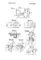
- FIG. 1 is a schematic view of the electrical network of a preferred embodiment of the present invention as applied to a camera shutter automatic timing system;
- FIG. 2 is a fragmentary top plan view of the battery receptacle section thereof in a partially closed condition
- FIG. 3 is a view similar to FIG. 2 with the battery receptacle being shown in a fully closed condition;
- FIG. 4 is a sectional view taken along line A-A in FIG. 2;
- FIG. 5 is a perspective view of another form of battery receptacle and switch structure which may be employed in the present system shown in a fully open condition;
- FIG. 6 is a view similar to FIG. 5 showing the receptacle in a partially closed condition
- FIG. 7 is a view similar to FIG. 6 showing the receptacle in a fully closed condition.
- the reference numeral 10 generally designates the shutter timing network which is of conventional construction and includes a solenoid 11 whose state of energization controls the closing of the camera shutter and is connected through the output of a solid state switch network 12 and a switch 14 across a battery E.
- the switch network 12 is controlled by the timing capacitor C connected to the input of switch network 12, the capacitor C being connected in series with an incident light exposed photoconductor PR across a battery E through switch 12.
- the capacitor C is shunted by a normally closed switch 13 which is opened with the opening of the shutter and the normally open switch 12 is closed with the depression of the shutter release button.
- the operation of network 10 is well known and need not be described.
- the battery E is replaceably housed in the usual manner in a battery housing in the camera body provided with terminal contacts which engage the terminals of the housed battery and a voltage polarity indicating network is connected between the battery housing terminals and is deactuated when the housing cover is fully closed.
- the polarity indicating network includes a diode D. an electric lamp L, a current limiting resistor R and a. switch S1 connected in series between the housing terminals.
- the diode D is so oriented as to conduct only when switch S1 is closed and the battery E is correctly oriented in the battery housing and the switch S1 is open when the battery housing cover is in its fully closed position and is closed when the cover is in a position retracted from its fully closed position.
- a transparent window 2 carrying suitable indicia, for example, the letters OK, is formed in a wall of the camera body 1 or the body of any associated device, proximate a cylinderical battery housing receptacle 4 closed at its inner end, open at its outer end, which registers with a corresponding opening in the body wall.
- the receptacle 4 is closed by a closure member or cover which is of circular shape and externally threaded to engage a corresponding thread in the body wall so that the cover 3 is advanced to its fully closed position at a predetermined point by rotation of the cover 3 from its initial engaged position.
- a switch actuating pin 3a depends from the outer border of cover 3. Contact terminals are centrally located on the bottom face of cover 3 and on the inside face of the bottom wall of the receptacle 4.
- the lamp L is suitably supported behind the window 2.
- the switch S1 is mounted with the body 1 proximate the upper border of receptacle 4 and includes a stationary contact element and a resilient switch arm C1 whose end registers with an aperture in the upper border of the receptacle 4 and which is in normal closed engagement with the switch stationary contact.
- the switch arm is so positioned relative to actuating pin 30 that the switch is normally closed until the cover 3 is turned to its closed position, in which closed position the pin 3a engages the end of the switch arm and retains it out of engagement with the switch stationary contact, thereby retaining switch S1 in open condition.
- the cover 3 is unscrewed and separated, the spent battery E removed from the receptacle 4 and replaced by a fresh battery E.
- the switch S1 is closed and the receptacle contacts engage the battery terminals, if the battery E is properly oriented in receptacle 4, the lamp L will light by reason of the low resistance of diode D thereby indicating the proper positioning of the battery E.
- the cover 3 is then turned to its closed position, as shown in FIG.
- the receptacle 24 includes a cylindrical wall and is closed at its bottom and open at its top and positioned in the manner of receptacle 4.
- Formed in the receptacle cylindrical wall is an L-shaped bayonet slot 4a including a vertical section extending to the top of the wall and a lower horizontal peripheral section.
- a pair of peripherally spaced flat contact elements 4b Positioned on the inner face of the lower border of the receptacle peripheral wall are a pair of peripherally spaced flat contact elements 4b which define the terminals of the switch S1.
- the closure member 23 is of the shape of a cap and includes a circular top wall and a coaxial depending skirt wall of lesser diameter than the top wall and of an outside diameter slightly less than the inside diameter of the receptacle cylindrical wall.
- a guide pin 5a radially outwardly projects from the closure member skirt wall and is adapted to slideably engage the bayonet slot 4a with the application of closure member 23.
- a peripherally extending conducting band 5b is positioned on the outside face of the lower border of the closure member skirt wall and is of a length somewhat greater than the distance between the remote edges of contact elements 4b.
- contact elements 4b and conductor band 5b are such that when closure member 23 is inserted in receptacle 24 as guided by the pin 5a travelling along the vertical section of bayonet slot 4a, conductor band 5b engages both contact elements 4b upon closure member 23 reaching its lowermost position to thereby close switch S1 and upon the rotation of closure member 23 to bring guide pin 5a from the elbow of bayonet slot 4a to the outer end of the horizontal arm thereof, the conductor band disengages one of the contact elements 4b to open the switch S1.
- the embodiment last described is similar to that described and their op: erations are likewise similar.
- a battery energized electrical device comprising a battery receiving receptacle having an access opening and including a separable cover member covering the battery positioned in the receptacle and movable in its covering position between an advanced predetermined closed position and a retracted position, a pair of contact elements, one of said contact elements being mounted inside of said receptacle and the other on said cover member, said pair of contact elements engaging the poles of the battery in said receptacle with said cover member in said covering position, a switch including a pair of electric contact members, means connected to said cover member permitting said contact members to be electrically connected in the retracted position and causing said contact members to be opened in the advanced predetermined closed position, and an indicating means for indicating whether said battery is positioned in the receptacle correctly with regard to its polarity, said indicating means being connected in series with said switch between said contact elements.
- said indicating means includes a diode and an electric lamp, said switch diode and lamp being connected in series between said contact elements.
- said switch includes a switch arm having one of said contact members resiliently urged into engagement with the other of said contact member, and said means connected to said cover including an actuating element located on and movable with the advance of said cover member along a path engaging said switch arm and urging it out of engagement, with the other of said switch contact members.
- a battery energized electrical device comprising a battery receiving receptacle having an access opening and including a cover member movable between an ad'- vanced predetermined closed position registering with said opening and a retracted position, a pair of contact elements for engaging the poles of a battery positioned in said receptacle in the advanced predetermined position and the retracted position, a switch including a pair of electric contact members, means connected to said cover permitting said contact members to be electrically connected in the retracted position and causing said contact members to be opened in the advanced predetermined closed position, and a polarity responsive electrically energized indicating means connected in series with said switch between said contact elements, said switch including a switch arm having one of said contact members resiliently urged into engagement with the other of said contact member, and said means connected to said cover including an actuating element located on and movable with the advance of said cover member along a path engaging said switch arm and urging it out of engagement with the other of said switch contact members, said receptacle
- a battery energized electrical device comprising a battery receiving receptacle having an access opening and including a cover member movable between an advanced predetermined closed position registering with said opening and a retracted position, a pair of contact elements for engaging the poles of a battery positioned in said receptacle in the advanced predetermined position and the retracted position, a switch including a pair of electric contact members, means connected to said cover permitting said contact members to be electrically connected in the retracted position and causing said contact members to be opened in the advanced predetermined closed position, and a polarity responsive electrically energized indicating means connected in series with said switch between said contact elements, said receptacle comprising a cylindrical housing, said cover member being rotatable in said housing between its advanced and retracted positions and said switch first and second contact members being located on the inside face of said receptacle and including a third peripherally extending contact member mounted on said cover member and movable therewith out of engagement with at least one of said pair of first and second contact members
- said receptacle has a bayonet slot formed in the cylindrical wall thereof and said cover member includes a depending cylindrical skirt wall slideably and axially telescoping said receptacle and having a projection engaging said bayonet slot, said third contact member being positioned on said skirt wall.
- a casing having an access opening to receive the dry cells and including a cover movable in its cell covering position registering with said access opening between an inserted position and a completely closed position, said cover being removable from the cell covering position;
- diode a diode, a switch and an indication means connected in series with each other; said diode, switch and indication means being connected in parallel with said load in relation to the power source;
- said diode being arranged in a direction which is conductive only when the dry cells are correctly placed, said switch including a pair of electric contact members engaging said cover resulting in said contact members being in open position when said cover is in said completely closed position, and said power source being connected with said load and said diode, switch and indication means when said cover is in said cell covering position.
Landscapes
- Physics & Mathematics (AREA)
- General Physics & Mathematics (AREA)
- Battery Mounting, Suspending (AREA)
- Primary Cells (AREA)
Applications Claiming Priority (1)
| Application Number | Priority Date | Filing Date | Title |
|---|---|---|---|
| JP1972055644U JPS5421704Y2 (cg-RX-API-DMAC10.html) | 1972-05-13 | 1972-05-13 |
Publications (1)
| Publication Number | Publication Date |
|---|---|
| US3879655A true US3879655A (en) | 1975-04-22 |
Family
ID=13004510
Family Applications (1)
| Application Number | Title | Priority Date | Filing Date |
|---|---|---|---|
| US357972A Expired - Lifetime US3879655A (en) | 1972-05-13 | 1973-05-07 | Polarity indicating battery receptacle |
Country Status (2)
| Country | Link |
|---|---|
| US (1) | US3879655A (cg-RX-API-DMAC10.html) |
| JP (1) | JPS5421704Y2 (cg-RX-API-DMAC10.html) |
Cited By (4)
| Publication number | Priority date | Publication date | Assignee | Title |
|---|---|---|---|---|
| US4044304A (en) * | 1974-01-28 | 1977-08-23 | Nippon Kogaku K.K. | Device for checking a d c source voltage relative to a predetermined value |
| US4075561A (en) * | 1976-11-01 | 1978-02-21 | General Electric Company | Programmable electrical apparatus containing a battery |
| EP0008872A1 (en) * | 1978-08-15 | 1980-03-19 | Nissan Motor Co., Ltd. | A circuit for indicating the reverse connection of connection leads with the terminals of an electromotive force source |
| US20030209413A1 (en) * | 2002-05-07 | 2003-11-13 | Mathias Haussmann | On/off switching device for an electric apparatus or component |
Families Citing this family (1)
| Publication number | Priority date | Publication date | Assignee | Title |
|---|---|---|---|---|
| JPS61179130A (ja) * | 1984-03-09 | 1986-08-11 | リオン株式会社 | 振動ユニット及びこのユニットを用いた振動感覚測定装置 |
Citations (10)
| Publication number | Priority date | Publication date | Assignee | Title |
|---|---|---|---|---|
| US2771526A (en) * | 1954-09-01 | 1956-11-20 | Revere Camera Co | Switch actuator apparatus |
| US2797405A (en) * | 1953-11-24 | 1957-06-25 | Francis C W Stelter | Container for valuables with alarm system |
| US3165037A (en) * | 1960-09-23 | 1965-01-12 | Agfa Ag Leverkusen Bayerwerk | Control for motion picture camera |
| US3200720A (en) * | 1960-09-23 | 1965-08-17 | Vockenhuber Karl | Arrangement for checking the battery voltage of an electrically driven film camera |
| US3243795A (en) * | 1963-03-08 | 1966-03-29 | Eastman Kodak Co | Battery condition indicator |
| US3259754A (en) * | 1962-10-23 | 1966-07-05 | Leslie C Matheson | Polarity indicator |
| US3371330A (en) * | 1965-01-18 | 1968-02-27 | Handebois Inc | Polarity reversal warning device |
| US3452347A (en) * | 1966-11-03 | 1969-06-24 | Eastman Kodak Co | Luminous diode battery condition indicator for camera |
| US3480860A (en) * | 1965-05-19 | 1969-11-25 | Prontor Werk Gauthier Gmbh | Testing means for an electronically operating automatic exposure system for photographic cameras |
| US3583800A (en) * | 1968-03-08 | 1971-06-08 | Minolta Camera Kk | Device for checking driving battery voltage in a motion-picture camera with a wide range of frame speed |
-
1972
- 1972-05-13 JP JP1972055644U patent/JPS5421704Y2/ja not_active Expired
-
1973
- 1973-05-07 US US357972A patent/US3879655A/en not_active Expired - Lifetime
Patent Citations (10)
| Publication number | Priority date | Publication date | Assignee | Title |
|---|---|---|---|---|
| US2797405A (en) * | 1953-11-24 | 1957-06-25 | Francis C W Stelter | Container for valuables with alarm system |
| US2771526A (en) * | 1954-09-01 | 1956-11-20 | Revere Camera Co | Switch actuator apparatus |
| US3165037A (en) * | 1960-09-23 | 1965-01-12 | Agfa Ag Leverkusen Bayerwerk | Control for motion picture camera |
| US3200720A (en) * | 1960-09-23 | 1965-08-17 | Vockenhuber Karl | Arrangement for checking the battery voltage of an electrically driven film camera |
| US3259754A (en) * | 1962-10-23 | 1966-07-05 | Leslie C Matheson | Polarity indicator |
| US3243795A (en) * | 1963-03-08 | 1966-03-29 | Eastman Kodak Co | Battery condition indicator |
| US3371330A (en) * | 1965-01-18 | 1968-02-27 | Handebois Inc | Polarity reversal warning device |
| US3480860A (en) * | 1965-05-19 | 1969-11-25 | Prontor Werk Gauthier Gmbh | Testing means for an electronically operating automatic exposure system for photographic cameras |
| US3452347A (en) * | 1966-11-03 | 1969-06-24 | Eastman Kodak Co | Luminous diode battery condition indicator for camera |
| US3583800A (en) * | 1968-03-08 | 1971-06-08 | Minolta Camera Kk | Device for checking driving battery voltage in a motion-picture camera with a wide range of frame speed |
Cited By (5)
| Publication number | Priority date | Publication date | Assignee | Title |
|---|---|---|---|---|
| US4044304A (en) * | 1974-01-28 | 1977-08-23 | Nippon Kogaku K.K. | Device for checking a d c source voltage relative to a predetermined value |
| US4075561A (en) * | 1976-11-01 | 1978-02-21 | General Electric Company | Programmable electrical apparatus containing a battery |
| EP0008872A1 (en) * | 1978-08-15 | 1980-03-19 | Nissan Motor Co., Ltd. | A circuit for indicating the reverse connection of connection leads with the terminals of an electromotive force source |
| US20030209413A1 (en) * | 2002-05-07 | 2003-11-13 | Mathias Haussmann | On/off switching device for an electric apparatus or component |
| US6762375B2 (en) * | 2002-05-07 | 2004-07-13 | Phonak Ag | On/off switching device for an electric apparatus or component |
Also Published As
| Publication number | Publication date |
|---|---|
| JPS4915432U (cg-RX-API-DMAC10.html) | 1974-02-08 |
| JPS5421704Y2 (cg-RX-API-DMAC10.html) | 1979-08-01 |
Similar Documents
| Publication | Publication Date | Title |
|---|---|---|
| US4281322A (en) | Fuse blowing detector | |
| US3643564A (en) | Indicator for flashlight photography | |
| GB1534430A (en) | Photographic flash devices | |
| US3374718A (en) | Low light and flash indicator for cameras | |
| US3879655A (en) | Polarity indicating battery receptacle | |
| US3667357A (en) | Automatic control devices for a camera | |
| JPS6237768B2 (cg-RX-API-DMAC10.html) | ||
| US3846806A (en) | Automatic flash device for a photographic camera | |
| US3524393A (en) | Camera having a receptacle for a source of current | |
| GB1493483A (en) | Photographic apparatus | |
| GB1360963A (en) | Camera flash sockets | |
| US3527149A (en) | Photographic camera with an electronic timing device controllable by light conditions | |
| GB1093731A (en) | Improvements in photographic camera shutters | |
| US3062091A (en) | Motor drive for motion picture camera | |
| US4503390A (en) | Switchless voltage, continuity and polarity indicator | |
| GB1522781A (en) | Battery checker for a camera with a flash light unit | |
| US3524392A (en) | Photographic camera with adjustable film speed control | |
| US2625863A (en) | Testing device for flash cameras | |
| US3641545A (en) | Device for indicating interrupted electric service | |
| US3821750A (en) | Indicating circuit for camera visually indicating need for flash exposures and periods of the exposures | |
| US3633476A (en) | Autoflash switching device for camera | |
| US3164075A (en) | Automatic battery test and control circuit for photographic cameras | |
| US3701942A (en) | Attachable test device for a flash device | |
| GB1072349A (en) | A camera flash circuit | |
| US3364832A (en) | Indicating mechanism for cartridge cameras |