US3875326A - Explosively operated welding cartridge - Google Patents
Explosively operated welding cartridge Download PDFInfo
- Publication number
- US3875326A US3875326A US331883A US33188373A US3875326A US 3875326 A US3875326 A US 3875326A US 331883 A US331883 A US 331883A US 33188373 A US33188373 A US 33188373A US 3875326 A US3875326 A US 3875326A
- Authority
- US
- United States
- Prior art keywords
- receptacle
- connecting element
- welding cartridge
- cartridge
- explosion welding
- Prior art date
- Legal status (The legal status is an assumption and is not a legal conclusion. Google has not performed a legal analysis and makes no representation as to the accuracy of the status listed.)
- Expired - Lifetime
Links
Images


Classifications
-
- B—PERFORMING OPERATIONS; TRANSPORTING
- B23—MACHINE TOOLS; METAL-WORKING NOT OTHERWISE PROVIDED FOR
- B23K—SOLDERING OR UNSOLDERING; WELDING; CLADDING OR PLATING BY SOLDERING OR WELDING; CUTTING BY APPLYING HEAT LOCALLY, e.g. FLAME CUTTING; WORKING BY LASER BEAM
- B23K20/00—Non-electric welding by applying impact or other pressure, with or without the application of heat, e.g. cladding or plating
- B23K20/06—Non-electric welding by applying impact or other pressure, with or without the application of heat, e.g. cladding or plating by means of high energy impulses, e.g. magnetic energy
- B23K20/08—Explosive welding
-
- H—ELECTRICITY
- H01—ELECTRIC ELEMENTS
- H01R—ELECTRICALLY-CONDUCTIVE CONNECTIONS; STRUCTURAL ASSOCIATIONS OF A PLURALITY OF MUTUALLY-INSULATED ELECTRICAL CONNECTING ELEMENTS; COUPLING DEVICES; CURRENT COLLECTORS
- H01R4/00—Electrically-conductive connections between two or more conductive members in direct contact, i.e. touching one another; Means for effecting or maintaining such contact; Electrically-conductive connections having two or more spaced connecting locations for conductors and using contact members penetrating insulation
- H01R4/08—Electrically-conductive connections between two or more conductive members in direct contact, i.e. touching one another; Means for effecting or maintaining such contact; Electrically-conductive connections having two or more spaced connecting locations for conductors and using contact members penetrating insulation effected by an explosion
Definitions
- An explosion welding cartridge for joining metallic components and more particularly electrical conductors including an outer explosive case having a ring of an explosive material located within the case and a connecting sleeve located within the ring, the sleeve having at least two apertures for receiving the components to be joined and a detonation cord or strip action-connected to the outer case.
- the present invention concerns an explosion welding cartridge for the joining of metallic components. in particular electric conductors.
- Prior art further includes explosion welding of metal plates and the joining ofcomponents by explosion compression.
- the explosion welding cartridge claimed hereunder is characterized by a case which is at least in parts rotation-symmetrical and which contains explosive arranged in the form of a ring closed upon itself and which presents at least one central aperture holding at least one joining part which presents at least one recess to receive at least one other part. and is further characterized by at least one detonating cord or detonating strip which is action-connected to the said case.
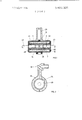
- FIG. I shows an axial section through an explosion welding cartridge for the bonding of two wires.
- FIG. 2 shows an end view of the cartridge according to FIG. I.
- FIG. 3 shows an axial section through a joining sleeve of the cartridge according to FIGS. 1 and 2;
- FIG. 4 shows retaining disks which are to be arranged on the end surfaces of the cartridge and which serve to hold the wires before blasting;
- FIG. 5 shows a view of part of an ignition case
- FIG. 6 shows an axial section through one halfof the explosive case
- FIG. 7 shows a top view of part of the explosive case according to FIG. 6;
- FIG. 8 shows a perspective view of a cartridge. with the wire ends introduced. immediately before blasting.
- FIG. I shows the construction of an explosion welding cartridge I.
- the cartridge 1 comprises two exactly identical explosive case halves 3 and 5. shown in FIGS. 6 and 7.
- the case halves 3 and 5 present an annular space 7 serving to receive explosive and are each provided outwards with an endpiece 8 and. opposite thereto. an edge and connecting element 9.
- the element 9 is divided into four sectors I I.
- the termination of the element 9 is formed by four ring surface sectors 12.
- the element 9 presents outer cone surfaces I4 alternating with inner cone surfaces I5. separated by slots I7.
- the case halves 3 and 5 also present a centrically arranged core channel I).
- the endpicce 8 presents a shoulder 20.
- the case halves 3 and 5, designed to be fitted together and cemented. are provided at their free ends. in the zone ofthe element 9.
- ignition case parts 23 and 24 are provided with a main groove 26 and with subsidiary grooves 27 and 28 serving to receive a single-piece detonating cord 29 or a detonating strip.
- the two subsidiary grooves 27 and 28 diverge with respect to the central plane. They form a divergence angle 30, which is between I) and about degrees. according to sleeve diameter and type of explosive.
- This divergence angle 30 ensures a uniform connection between the parts to be welded. as the propagation front ofthe detonation proceeds in a manner uniform and perpendicular to the sleeve axis, In two-piece connections. the cord 29 is only laid round once. Instead. it may also be arranged inside the explosive 4].
- the free end of the two ignition case parts 23 and 24 presents an O-ring 32 serving to press the ignition cap 33 with the fuse cord 35 against the ends of the detonating cord 29. This. however. is only done at erection on the site.
- the ends ofthe ignition ease parts 23 and 24 are bent in a direction perpendicular to the sleeve axis in order to prevent any splintcrs'of the cap 33 from damaging the conductors.
- the bend in the example shown is such that the explosive case axis and the ignition cap axis are askew with respect to each other.
- FIG. 3 shows the connecting sleeve 34 associated with the explosion welding cartridge 1.
- the sleeve is provided towards the middle with two guide bores 36 separated from each other by a stop 37. Adjoining each guide bore 36 outwards is a welding bore 39.
- FIG. I contains explosive 4
- FIG. I further shows the welding end of a wire 43 whose outer surface is separated from the inner surface of the welding bore 39 by an annular space 44.
- the explosion welding cartridge is assembled as follows:
- a quantity of explosive is gouged out of a cake by means of the case halves 3 and 5 pressed into the cake. Then the explosive present in the core channel [9 is pressed out.
- the outer and inner cone surfaces 14 and IS respectively are coated with an adhesive. and the two case halves 3 and 5, which are identical in construction. are turned so that the cone surfaces 14 and I5 come to lie conversely on the other surfaces 15 and I4.
- the detonation cord 29 is wound twice round the case 3/5 in the zone of the middle thereof. after which the two ignition case parts 23 and 24 are slipped on to the case 3/5.
- the detonating cord 29 is suitably laid into the grooves 26, 27 and 28. and the whole unit is glued together.
- the connecting sleeve 34 is suitably laid into the grooves 26, 27 and 28. and the whole unit is glued together.
- the disk 46 presents inward-pointing teeth (FIG. 4). These teeth define an inner diameter which is slightly smaller than that of the conductor wire 43 to be welded. in such a manner that the wire. when inserted into the teeth. is secured against falling out before blastingv
- the disks 46 serving to hold the conductors 43 before blasting are made of an elastic plastic. such as Nylon. Delrin or the like. Instead. they may be punched from metal. Also.
- the wire ends to be welded are brushed bright.
- the tabs 48 at the two ends ofthe case 3/5 are removed. and the cleaned wire ends are inserted into the sleeve 34 in such a manner that they are centered in the guide bores 36 and are held at the stops 37 in axially correct position.
- the two wire ends are thus held both in the sleeve 34 and in the retaining disks 46.
- the end of the fuse cord 35 is lit with a match or a flame.
- Detonation of the explosive 41 results in a bond between the wire ends and the sleeve 34. except that the outer edge portions of the sleeve 34 are not welded to the wire 43., an advantage particularly in terms of strength. as no notch affects arise. It has thus been found advantageous to arrange the explosive along the sleeve outwards in such a manner that the end of the sleeve does not undergo welding along at least 171 of the sleeve length. The other parts of the cartridge are either blasted off or evaporated by the explosion.
- the explosion welding cartridge can be used to bond wires of the most varied materials. in particular metals, and multi-wire conductors. strands. etc. It is also possible to weld cable shoes to conductors and to produce simple or multiple branches of wires or the like.
- the explosion welding cartridge may be entbedded in a soundprool'ing mass.
- a soundprool'ing mass such as foam plastic alone or combined with a sand bed.
- the case parts of the cartridge are preferably made of plastic. such as polystyrene or the like.
- An explosion welding cartridge l'orjoining metallic components which comprises:
- hollow receptacle substantially symmetrical about its axis.
- said hollow receptacle consisting of a pair of parts which fit together. each of said parts including an inner annular wall and an outer annular wall which define an annular space therebetween. said inner annular wall defining a central aperture;
- each recess comprising a first axial opening extending inwardly from the respective end of said connecting element and a second axial opening ofsmallcr cross section than said first axial opening extending inwardly from said first axial opening and terminating in a reduced section to limit inward movement ofthe metallic components into said connecting element;
- an ignition case attached to said receptacle for receiving a detonation cord.
- said detonating means comprises a detonation cord provided with an explosive having a disruptive power exceeding the disruptive power of said explosive charge.
- the explosion welding cartridge of claim 1 which includes retaining means located at opposite ends of said receptacle for holding the metallic components to be inserted into said connecting element.
- said retaining means comprises retaining discs located at opposite ends of said receptacle, each retaining disc being provided with a central aperture for receiving the corresponding metallic component inserted into said connecting element and including teeth extending inwardly into its central aperture to engage and hold the metallic component in said connecting element.
- the explosion welding cartridge of claim 1. which includes:
- removable tabs located at opposite ends of said receptacle for covering said recesses in said connecting element to protect said connecting element against corrosion.
- An explosively operated welding cartridge for joining metallic components which comprises:
- a hollow receptacle substantially symmetrical about its axis
- an explosive charge arranged within said receptacle in the form of a closed ring to provide a central aperture
- each recess comprising a first axial opening extending inwardly from the respective end of said connecting element and a second axial opening otsmaller cross-section than said first axial ally from the annular portion which mates with the opening extending inwardly from said first axial elongated portion of the other part; and opening and lcrminuliflg in i C CC 506mm to a fastening element surrounding said elongated porlimit inward movement of the metallic component ⁇ inns f id t to hold said case parts into said connecting element.
Landscapes
- Engineering & Computer Science (AREA)
- Mechanical Engineering (AREA)
- Connections Effected By Soldering, Adhesion, Or Permanent Deformation (AREA)
- Pressure Welding/Diffusion-Bonding (AREA)
Priority Applications (1)
| Application Number | Priority Date | Filing Date | Title |
|---|---|---|---|
| US05/546,888 US3955741A (en) | 1972-02-29 | 1975-02-04 | Explosively operated welding cartridge |
Applications Claiming Priority (1)
| Application Number | Priority Date | Filing Date | Title |
|---|---|---|---|
| CH292072A CH535629A (de) | 1972-02-29 | 1972-02-29 | Spreng-Schweisspatrone |
Related Child Applications (1)
| Application Number | Title | Priority Date | Filing Date |
|---|---|---|---|
| US05/546,888 Continuation-In-Part US3955741A (en) | 1972-02-29 | 1975-02-04 | Explosively operated welding cartridge |
Publications (1)
| Publication Number | Publication Date |
|---|---|
| US3875326A true US3875326A (en) | 1975-04-01 |
Family
ID=4244585
Family Applications (1)
| Application Number | Title | Priority Date | Filing Date |
|---|---|---|---|
| US331883A Expired - Lifetime US3875326A (en) | 1972-02-29 | 1973-02-12 | Explosively operated welding cartridge |
Country Status (15)
| Country | Link |
|---|---|
| US (1) | US3875326A (fr) |
| JP (1) | JPS5423350B2 (fr) |
| AT (1) | AT341601B (fr) |
| AU (1) | AU467792B2 (fr) |
| BE (1) | BE796060A (fr) |
| BR (1) | BR7301359D0 (fr) |
| CA (1) | CA981525A (fr) |
| CH (1) | CH535629A (fr) |
| DE (1) | DE2302003C3 (fr) |
| FR (1) | FR2174034B1 (fr) |
| GB (1) | GB1409634A (fr) |
| IT (1) | IT984371B (fr) |
| NL (1) | NL170476C (fr) |
| NO (1) | NO138756C (fr) |
| SE (1) | SE404425B (fr) |
Cited By (5)
| Publication number | Priority date | Publication date | Assignee | Title |
|---|---|---|---|---|
| US4057187A (en) * | 1974-11-27 | 1977-11-08 | Western Electric Company, Inc. | Joining wire-like members |
| US4600332A (en) * | 1985-01-11 | 1986-07-15 | Explosive Fabricators, Inc. | Aluminum/titanium transition joint between aluminum and steel bodies |
| US20080233787A1 (en) * | 2007-03-12 | 2008-09-25 | Fci Americas Technology, Inc. | Implosion Connector and Method for Use With Transmission Line Conductors Comprising Composite Cores |
| US20090293709A1 (en) * | 2008-05-27 | 2009-12-03 | Joynt Vernon P | Apparatus for defeating high energy projectiles |
| US8151685B2 (en) | 2006-09-15 | 2012-04-10 | Force Protection Industries, Inc. | Apparatus for defeating high energy projectiles |
Families Citing this family (2)
| Publication number | Priority date | Publication date | Assignee | Title |
|---|---|---|---|---|
| JPS5928299Y2 (ja) * | 1978-10-23 | 1984-08-15 | 三菱電機株式会社 | 冷蔵庫の冷却器取付装置 |
| CN108087554B (zh) * | 2017-12-15 | 2024-04-26 | 中国工程物理研究院流体物理研究所 | 爆炸容器孔道的楔型密封结构及密封方法 |
Citations (4)
| Publication number | Priority date | Publication date | Assignee | Title |
|---|---|---|---|---|
| US3019284A (en) * | 1959-12-29 | 1962-01-30 | Burndy Corp | Gripping cup to retain a conductor in a connector |
| US3184535A (en) * | 1962-01-09 | 1965-05-18 | Cable Covers Ltd | Compression connector for joining wires |
| US3364304A (en) * | 1963-11-27 | 1968-01-16 | Amp Inc | Electrical cable splice with explosive charge |
| US3780927A (en) * | 1973-01-24 | 1973-12-25 | B Surnin | Envelope for explosive connection of metal pipes |
-
1972
- 1972-02-29 CH CH292072A patent/CH535629A/de not_active IP Right Cessation
-
1973
- 1973-01-16 DE DE2302003A patent/DE2302003C3/de not_active Expired
- 1973-01-29 GB GB435273A patent/GB1409634A/en not_active Expired
- 1973-02-05 AU AU51800/73A patent/AU467792B2/en not_active Expired
- 1973-02-08 AT AT113073A patent/AT341601B/de not_active IP Right Cessation
- 1973-02-08 CA CA163,257A patent/CA981525A/en not_active Expired
- 1973-02-12 US US331883A patent/US3875326A/en not_active Expired - Lifetime
- 1973-02-14 IT IT67348/73A patent/IT984371B/it active
- 1973-02-20 FR FR7305941A patent/FR2174034B1/fr not_active Expired
- 1973-02-21 NL NLAANVRAGE7302371,A patent/NL170476C/xx not_active IP Right Cessation
- 1973-02-22 NO NO727/73A patent/NO138756C/no unknown
- 1973-02-23 BR BR731359A patent/BR7301359D0/pt unknown
- 1973-02-28 SE SE7302857A patent/SE404425B/xx unknown
- 1973-02-28 BE BE128180A patent/BE796060A/fr not_active IP Right Cessation
- 1973-02-28 JP JP2419273A patent/JPS5423350B2/ja not_active Expired
Patent Citations (4)
| Publication number | Priority date | Publication date | Assignee | Title |
|---|---|---|---|---|
| US3019284A (en) * | 1959-12-29 | 1962-01-30 | Burndy Corp | Gripping cup to retain a conductor in a connector |
| US3184535A (en) * | 1962-01-09 | 1965-05-18 | Cable Covers Ltd | Compression connector for joining wires |
| US3364304A (en) * | 1963-11-27 | 1968-01-16 | Amp Inc | Electrical cable splice with explosive charge |
| US3780927A (en) * | 1973-01-24 | 1973-12-25 | B Surnin | Envelope for explosive connection of metal pipes |
Cited By (8)
| Publication number | Priority date | Publication date | Assignee | Title |
|---|---|---|---|---|
| US4057187A (en) * | 1974-11-27 | 1977-11-08 | Western Electric Company, Inc. | Joining wire-like members |
| US4600332A (en) * | 1985-01-11 | 1986-07-15 | Explosive Fabricators, Inc. | Aluminum/titanium transition joint between aluminum and steel bodies |
| US8151685B2 (en) | 2006-09-15 | 2012-04-10 | Force Protection Industries, Inc. | Apparatus for defeating high energy projectiles |
| US20080233787A1 (en) * | 2007-03-12 | 2008-09-25 | Fci Americas Technology, Inc. | Implosion Connector and Method for Use With Transmission Line Conductors Comprising Composite Cores |
| AU2008226793B2 (en) * | 2007-03-12 | 2012-07-05 | Hubbell Incorporated | Implosion connector and method for use with transmission line conductors comprising composite cores |
| US8246393B2 (en) * | 2007-03-12 | 2012-08-21 | Hubbell Incorporated | Implosion connector and method for use with transmission line conductors comprising composite cores |
| CN101641838B (zh) * | 2007-03-12 | 2013-09-18 | 豪倍公司 | 用于包含复合芯的传输线导体的内爆电连接器和方法 |
| US20090293709A1 (en) * | 2008-05-27 | 2009-12-03 | Joynt Vernon P | Apparatus for defeating high energy projectiles |
Also Published As
| Publication number | Publication date |
|---|---|
| JPS48100354A (fr) | 1973-12-18 |
| CH535629A (de) | 1973-04-15 |
| AU5180073A (en) | 1974-08-08 |
| NO138756C (no) | 1978-11-08 |
| AU467792B2 (en) | 1975-12-11 |
| GB1409634A (en) | 1975-10-08 |
| NL170476C (nl) | 1982-11-01 |
| FR2174034B1 (fr) | 1976-11-05 |
| AT341601B (de) | 1978-02-27 |
| DE2302003A1 (de) | 1973-09-06 |
| NL7302371A (fr) | 1973-08-31 |
| NL170476B (nl) | 1982-06-01 |
| NO138756B (no) | 1978-07-31 |
| SE404425B (sv) | 1978-10-02 |
| IT984371B (it) | 1974-11-20 |
| BR7301359D0 (pt) | 1974-05-16 |
| FR2174034A1 (fr) | 1973-10-12 |
| ATA113073A (de) | 1977-06-15 |
| JPS5423350B2 (fr) | 1979-08-13 |
| BE796060A (fr) | 1973-06-18 |
| CA981525A (en) | 1976-01-13 |
| DE2302003B2 (de) | 1975-04-10 |
| DE2302003C3 (de) | 1975-12-11 |
Similar Documents
| Publication | Publication Date | Title |
|---|---|---|
| US2367206A (en) | Method of joining objects | |
| US3875326A (en) | Explosively operated welding cartridge | |
| US4293178A (en) | Coupling for an electric cable | |
| US2306206A (en) | Electric coupling | |
| CN105191019A (zh) | 用于在线缆端部处的紧密接合的方法及配置线缆 | |
| US4026628A (en) | Electrical connector for cables and magnetic forming process for same | |
| EP1747420B1 (fr) | Connecteur sans detonateur a charge directe pour tubes a choc | |
| US20180138464A1 (en) | Battery cell housing and method for production of same | |
| JPH07335336A (ja) | オーディオ用コネクタ | |
| US3088993A (en) | Crimp connector | |
| US2909758A (en) | Explosive terminal and method of firing | |
| US2427518A (en) | Electrical connecting conductor | |
| US3052750A (en) | High tensile splice | |
| JPS584278A (ja) | プラグ及びレセプタクルコネクタ用のケ−ブルシ−ルド終端手段 | |
| US5521996A (en) | Electrical and fiber-optic connector | |
| US3955741A (en) | Explosively operated welding cartridge | |
| GB601670A (en) | An improved method and apparatus for attaching connections to stranded cables | |
| JP3061253B2 (ja) | 分岐接続用ケース部材、及び分岐接続方法 | |
| US3399270A (en) | Terminal for cable comprising a plurality of sheathed conductors | |
| US3520986A (en) | No-strip explosion connector | |
| US4451695A (en) | Connector assembly | |
| US4478475A (en) | Method and plug for securing a connecting wire to a tubular pin | |
| US4623213A (en) | Method for joining two aluminum conductors of electric cables and the joint thus obtained | |
| KR20010078027A (ko) | 전기뇌관용 각선 접속구 및 모선 접속구 | |
| JPH04329276A (ja) | コネクター構造 |