US387180A - John k - Google Patents
John k Download PDFInfo
- Publication number
- US387180A US387180A US387180DA US387180A US 387180 A US387180 A US 387180A US 387180D A US387180D A US 387180DA US 387180 A US387180 A US 387180A
- Authority
- US
- United States
- Prior art keywords
- shows
- rope
- cylinder
- handles
- frame
- Prior art date
- Legal status (The legal status is an assumption and is not a legal conclusion. Google has not performed a legal analysis and makes no representation as to the accuracy of the status listed.)
- Expired - Lifetime
Links
- 239000002965 rope Substances 0.000 description 28
- 238000010276 construction Methods 0.000 description 6
- 238000007906 compression Methods 0.000 description 2
Images
Classifications
-
- A—HUMAN NECESSITIES
- A62—LIFE-SAVING; FIRE-FIGHTING
- A62B—DEVICES, APPARATUS OR METHODS FOR LIFE-SAVING
- A62B1/00—Devices for lowering persons from buildings or the like
- A62B1/06—Devices for lowering persons from buildings or the like by making use of rope-lowering devices
- A62B1/14—Devices for lowering persons from buildings or the like by making use of rope-lowering devices with brakes sliding on the rope
Definitions
- the object of my invention is to create a light, safe, portable fire-escape of simple and inexpensive construction, of such size and weight as to be easily carried by a traveler and afford him the means of lowering himself safely from the windows of any building.
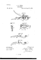
- Figure 1 shows the fire'escape with a part of the frame removed.
- Fig. 2 shows manner of descent.
- Fig. 3 shows the frame in perspective.
- Fig. 4c shows the female handle, and
- Fig. 5 shows the male handle, detached.
- A shows the frame.
- B shows one handle
- C shows the other handle
- H shows the orifices through which the rope enters. H shows the orifice through which it escapes from the handles when the rope is being drawn through from the top.
- J shows the holes for the pins.
- K shows the slots in the sides of the frames below the cylinder.
- L shows the handle, which may be attached to the sides of the frame, and to which the belt may be made fast.
- L shows the cylinder hollow, through which the belt of the sling may be passed.
- the pin through the slot K prevents that handle from swinging out of position.
- the rope is passed from beneath through the handles and around the cylinder and out at the upper end. This end is made fast to any object in the room, and the person seated in the sling governs his descent by pressure on the handles.
- the rope from above enters through an orifice made of grooves in the upper ends of the handles, near one side of the frame, and, passing around the cylinder, passes out through other grooves made in parts of the handles below the cylinder, parallel to and near the other side of the frame, and thus the rope is guided in its passage and prevented from lapping or binding upon itself.
- the handles are so curved and concaved that they are adapted to the size of the cylinder and rope, and by compression on the handles give a nearly equal pressure nearly all the way around the cylinder. Thus by frietion so distributed the rapidity of the descent is easily controlled. By this construction a very small amount of pressure is given at any one point on the rope, and located so far from the vertical line that it controls its action with greatly-reduced liability to break it.
- An ordinary belt and strap form the means of securing the person to the escape, and that is of no peculiar construction, but may be varied according to the strength of the person, and several persons may descend by the escape at once.
- the handles B In combination with the frame A and cylinder G, the handles B 0, provided with the grooves or notches H H, adapted to guide the coiled rope in proper position around the cylinder, substantially as and for the purpose herein set forth.
Description
I'IED STATES PATENT rrIcE.
JOHN K. ONEIL, OF POUGHKEEPSIE, NEW YORK, ASSIGNOR TO DORSEY NEVILLE, OF SAME PLACE.
FlRE ==ESCAPE.
SPECIFICATION forming part of Letters Patent No. 387.180, dated July 31, 1888 (No model.)
To all whomit may concern:
Be it known that I, JOHN K. ONEIL, of the city of Poughkeepsie, county of Dutchess, and State of New York, have invented a new and useful Improvement in Fire-Escapes, of which the following is a specification, reference being had to the accompanying drawings.
The object of my invention is to create a light, safe, portable fire-escape of simple and inexpensive construction, of such size and weight as to be easily carried by a traveler and afford him the means of lowering himself safely from the windows of any building.
Figure 1 shows the fire'escape with a part of the frame removed. Fig. 2 shows manner of descent. Fig. 3 shows the frame in perspective. Fig. 4c shows the female handle, and Fig. 5 shows the male handle, detached.
Like letters indicate like parts.
A shows the frame.
B shows one handle, and C shows the other handle.
G shows the cylinder.
E shows the rope.
H shows the orifices through which the rope enters. H shows the orifice through which it escapes from the handles when the rope is being drawn through from the top.
[shows the pins holding the handles into the frame.
J shows the holes for the pins.
K shows the slots in the sides of the frames below the cylinder.
L shows the handle, which may be attached to the sides of the frame, and to which the belt may be made fast.
L shows the cylinder hollow, through which the belt of the sling may be passed. The pin through the slot K prevents that handle from swinging out of position.
To use my escape, the rope is passed from beneath through the handles and around the cylinder and out at the upper end. This end is made fast to any object in the room, and the person seated in the sling governs his descent by pressure on the handles. The rope from above enters through an orifice made of grooves in the upper ends of the handles, near one side of the frame, and, passing around the cylinder, passes out through other grooves made in parts of the handles below the cylinder, parallel to and near the other side of the frame, and thus the rope is guided in its passage and prevented from lapping or binding upon itself.
In using my escape the rope passes in an opposite direction from that above described.
The handles are so curved and concaved that they are adapted to the size of the cylinder and rope, and by compression on the handles give a nearly equal pressure nearly all the way around the cylinder. Thus by frietion so distributed the rapidity of the descent is easily controlled. By this construction a very small amount of pressure is given at any one point on the rope, and located so far from the vertical line that it controls its action with greatly-reduced liability to break it.
The operative parts of this escape are covered, and no part of a persons dress can by any contingency become entangled with the rope in its passage around the cylinder.
No claim is made for any friction governing the passage of the rope, except that applied by the sides of the handles impinging the rope against the cylinder.
An ordinary belt and strap form the means of securing the person to the escape, and that is of no peculiar construction, but may be varied according to the strength of the person, and several persons may descend by the escape at once.
Having thus described my invention, what I claim, and desire to obtain Letters Patent for, 1s
1. The combination of a frame, a fixed hollow cylinder in the middle of the frame and adapted to have the rope coil around it, and two handles pivoted to the frame on opposite sides of the cylinder and adapted to be pressed against the rope-coil on opposite sides of the cylinder when the handles of the levers are grasped in the hand and pressed toward each other, substantially as and for the purpose herein specified.
2. In combination with the frame A and cylinder G, the handles B 0, provided with the grooves or notches H H, adapted to guide the coiled rope in proper position around the cylinder, substantially as and for the purpose herein set forth.
JOHN K. ON'EIL.
l'CO
Publications (1)
| Publication Number | Publication Date |
|---|---|
| US387180A true US387180A (en) | 1888-07-31 |
Family
ID=2456163
Family Applications (1)
| Application Number | Title | Priority Date | Filing Date |
|---|---|---|---|
| US387180D Expired - Lifetime US387180A (en) | John k |
Country Status (1)
| Country | Link |
|---|---|
| US (1) | US387180A (en) |
-
0
- US US387180D patent/US387180A/en not_active Expired - Lifetime
Similar Documents
| Publication | Publication Date | Title |
|---|---|---|
| US785019A (en) | Fire-escape. | |
| US682869A (en) | Fire-escape. | |
| US416550A (en) | Fire-escape | |
| US387180A (en) | John k | |
| US315025A (en) | Fire-escape | |
| US300857A (en) | Lewis j | |
| US428812A (en) | johanson | |
| US209137A (en) | Improvement in fire-escapes | |
| US356436A (en) | Samuel a | |
| US383211A (en) | Fire-escape | |
| US306078A (en) | Fire-escape | |
| US542641A (en) | Vitus hembacher | |
| US1229394A (en) | Portable fire-escape. | |
| US506707A (en) | Portable friction fire-escape | |
| US1216041A (en) | Fire-escape. | |
| US770012A (en) | Fire-escape. | |
| US682082A (en) | Fire-escape. | |
| US284763A (en) | Fire-escape | |
| US382574A (en) | Fire-escape | |
| US292981A (en) | Fire-escape | |
| US272259A (en) | Fire-escape | |
| US450796A (en) | Fire-escape | |
| US1264179A (en) | Portable fire-escape. | |
| US284431A (en) | Charles johnson | |
| US738785A (en) | Fire-escape. |