US3868302A - Thermal shield of a nuclear reactor - Google Patents
Thermal shield of a nuclear reactor Download PDFInfo
- Publication number
- US3868302A US3868302A US142581A US14258171A US3868302A US 3868302 A US3868302 A US 3868302A US 142581 A US142581 A US 142581A US 14258171 A US14258171 A US 14258171A US 3868302 A US3868302 A US 3868302A
- Authority
- US
- United States
- Prior art keywords
- core
- portions
- nuclear
- barrel
- pressure vessel
- Prior art date
- Legal status (The legal status is an assumption and is not a legal conclusion. Google has not performed a legal analysis and makes no representation as to the accuracy of the status listed.)
- Expired - Lifetime
Links
Images

Classifications
-
- G—PHYSICS
- G21—NUCLEAR PHYSICS; NUCLEAR ENGINEERING
- G21C—NUCLEAR REACTORS
- G21C11/00—Shielding structurally associated with the reactor
- G21C11/08—Thermal shields; Thermal linings, i.e. for dissipating heat from gamma radiation which would otherwise heat an outer biological shield ; Thermal insulation
-
- Y—GENERAL TAGGING OF NEW TECHNOLOGICAL DEVELOPMENTS; GENERAL TAGGING OF CROSS-SECTIONAL TECHNOLOGIES SPANNING OVER SEVERAL SECTIONS OF THE IPC; TECHNICAL SUBJECTS COVERED BY FORMER USPC CROSS-REFERENCE ART COLLECTIONS [XRACs] AND DIGESTS
- Y02—TECHNOLOGIES OR APPLICATIONS FOR MITIGATION OR ADAPTATION AGAINST CLIMATE CHANGE
- Y02E—REDUCTION OF GREENHOUSE GAS [GHG] EMISSIONS, RELATED TO ENERGY GENERATION, TRANSMISSION OR DISTRIBUTION
- Y02E30/00—Energy generation of nuclear origin
- Y02E30/30—Nuclear fission reactors
Definitions
- the level of radiation impinging on the reactor vessel increases as the amount of water and steel between the periphery of the core and the inner surface of the reactor vessel decreases. Since a given thickness of steel reduces the radiation level approximately twice as much as an equal thickness of water, reactor manufacturers have often utilized steel thermal shields to reduce the exposure of the reactor vessel to an adequate level.
- the nuclear core is contained and surrounded by a fabricated baffle structure of a generally rectangular configuration.
- the baffle structure is attached to the core-barrel by plate means 'which achieve the transition from the rectangular geometry of the core to the cylindrical geometry of the core-barrel.
- the core-barrel is generally displaced from the inside surface of the pressure vessel and an annular flow path is formed therebetween.
- a cylindrical thermal shield is generally attached to the core-barrel and situated approximately an equal distance from the inner surface of the pressure vessel and the outer surface of the core-barrel. Since the thermal shield is located in a flow stream of relatively high velocity and experiences a thermal growth unequal to that of the core barrel to which it is attached, it is a difficult component to design and has historically been a major item of expense to reactor manufacturers.
- the neutron flux level impinging on the inside of a reactor vessel varies markedly in the circumferential direction.
- the highest flux levels are in the vicinity of the corners of the rectangular configuration.
- the lower core-barrel metal thickness is increased selectively in those regions proximate the corners of the core. If the added thickness is made equal to the thickness of the normally included thermal shield, the maximum radiation exposure is essentially the. samev as thelevel that would result with a separate cylindrical thermal shield.
- the region of increased thickness should extend about the circumference of the core sufficiently to insure that the vessel exposure does not exceed a maximum value at any point.
- An increase in the thickness of the lower core barrel may be achieved by affixing steel plates thereto.
- the steel plates may cover an arc of 20 to 30, and for the usual core, would be situated on 45 axes which intersect the corners of the core when viewed from above.
- the steel plates may suitably be bolted and doweled to the core-barrel.
- the inside surface of the plates may be separated slightly from the core-barrel to permit cooling water to flow between the core-barrel and the plates.
- overlapping plates may be utilized to achieve the required overall lengths.
- the several plates may then have mitered joints between them to prevent local leakage of neutrons. These plates may then move relative to each other so as to minimize the thermal stresses due to differential expansion.
- the steel plates may be located on the inside of the core-barrel or may even form a part of the core-barrel structure, as casted.
- FIG. 1 is a partially sectioned view in elevation of a nuclear reactor incorporating the improvement of this invention
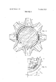
- FIG. 2 is a cross-sectional view at the inlet and outlet level looking downwardly;
- FIG. -3 depicts a comparison of the flux levels with a full thermal shield and the shielding of this invention
- FIG. 4 is an expanded view of a section of FIG. 2;
- FIG. 5 is an isometric view of the reactor internals proximate a corner of the nuclear core.
- FIGS. 1 and 2 there is illustrated a nuclear reactor incorporating the vessel shield means of this invention.
- a pressure vessel 10 is shown which forms a tight pressurized container when sealed by a head assembly 12.
- the pressure vessel 10 has coolant flow inlet means 14 and coolant flow outlet means 16 affixed in and through the walls thereof.
- the head assembly 12 has a plurality of head penetration adapters l3 sealed in and through its substantially hemispherical wall.
- the head penetration adaptors 13 are aligned parallel with the axis of the pressure vessel 10 and receivably support mechanisms 15 which actuate control rods (not shown) to stabilize and control the reactor in a manner well known in the art.
- a core-barrel 20 is supportedly suspended from an inwardly extending projection just below the top of the pressure vessel 10, and an upper support plate (not shown), an upper core plate 26, and a lower core plate 28 are also substantially supported by the same inward projection.
- the lower end of the core-barrel 20 is closed by a heavy wall bottom section having numerous holes therein.
- the region between the upper core plate 26 and the lower core plate 28 is filled with a plurality of fuel assemblies 34; all of which are substantially identical.
- the parallel array of fuel assemblies 34 include a plurality of fuel rods (not shown) with guide tubes (not shown) interspersed therebetween and held in a fixed relationship each to the other by an egg crate type grid structure of well known construction in the art.
- a baffle 36 surrounds the assemblies 34 and lends additional support thereto.
- the baffle 36 fits tightly to the outward contours of the grouping of fuel assemblies 34 and may be constructed from a plurality of straight sections such that the outward configuration of the core is generally rectangular, i.e., made up of a plurality of rectangles overlaid.
- the baffle 36 may be laterally supported by and affixed to the core barrel 20 with the plurality of separator plates (not shown).
- the flux dosage of the vessel would depend upon the amount of moderating fluid and steel between the outward periphery of the nuclear core and the inner wall of the pressure vessel 10. -In the absence of such shielding, this dosage might be such as to necessitate a periodic annealing of the pressure vessel 10. Such a procedure is extremely complicated and expensive.
- the thickness in structural and shielding material interposed between the nuclear core and the inner wall of the pressure vessel 10 is increased in those regions adjacent those portions of the nuclear core which are closest to the inner wall of the pressure vessel 10.
- steel plates can be affixed to either the core-barrel20 or the pressure vessel 10 in those regions where the pressure vessel would otherwise be subject to maximum neutron flux; said plates being generally designated by the numeral 40.
- Curves 42 and 44 in FIG. 3 show a comparison of the flux distribution at the inner surface of the pressure vessel 10 under the current practice and with the new arrangement.
- Curve 42 designates the flux distribution under the current practice and curve 44 shows the flux distribution which would be present with the arrangement of this invention.
- the maximum flux is identical in both cases although intermediate flux levelsare slightly higher with the new arrangement.
- the new arrangement has for its purpose a reduction of the maximum flux levels from levels which would exist in the absence of shielding while allowing intermediate flux values to be slightly increased due to a lack of thermal shielding surrounding certain portions of the core, i.e., those portions being farthest from the inner wall of the pressure vessel 10.
- the partial thermal shield includes a plurality of shield segments 48 which abutt along mitered joints 50 (see FIG. 5).
- the inner surfaces of the segmented shields 48 are affixed through blocks 49 to the core barrel 20 to allow coolant flow to pass between the core-barrel 20 and the shields 48 so as to reduce the thermal stresses acting on same (see FIG. 4).
- the individual segmented shields 48 may be bolted or otherwise suitably affixed to the core barrel 20. A suggested connecting structure is shown most clearly in FIG. 4.
- Blocks.49 are first welded to the core-barrel 20.
- shield segments 48 are provided with cut-backs 54 which properly locate the segments 48 with respect to the blocks 49.
- Dowel pins 56 are then pressed through the segments 48 and the blocks 49 into the core-barrel 20. Sufficient pins 56 are utilized to assume a substantial portion of the shear stress due to thermal growth.
- the segments are then affixed to the core-barrel 20 with long bolts 58 which threadedly engage the corebarrel 20.
- the holes for the bolts 58 should be oversized to minimize shearing action on the bolts 58.
- Alternative configurations contemplated include the affixing of the shielding means 40 to the inside of the core-barrel 20 should sufficient space exist between the core-barrel 20 and the baffle 36 surrounding the nuclear core. Also contemplated is affixing the shield 40 to the inside surface of the reactor vessel 20. These various embodiments are all suitable for reducing the maximum flux impinging upon those regions of the reactor vessel most proximate the nuclear fuel.
- a nuclear reactor including, in combination:
- an elongated upstanding nuclear core within said pressure vessel comprising a plurality of fuel assemblies, said fuel assemblies being situated in side-by-side relationship such that the core has a generally rectangular configuration in plan view with some portions of the core closer to the inner side wall of the pressure vessel than other portions; supportive and shielding structures being interposed between the nuclear core and the pressure vessel and coextending at least in part with the longitudinal dimension of said elongated core, the coextending parts of said interposed structures having an increased thickness adjacent said some portions.
- the interposed structure includes a cylindrical core-barrel supported by said pressure vessel and surrounding said nuclear core and wherein the core-barrel is of an increased thickness adjacent said some portions.
- a nuclear reactor including, in combination: an upstanding pressure vessel; an elongated upstanding nuclear core within said pressure vessel comprising a plurality of fuel assemblies, said fuel assemblies being situated in side-by-side relationship such that the core has a generally rectangular configuration in plan view with some portions of the core closer to the inner side wall of the pressure vessel than other portions;
- thermal shield means interposed between said vessel and said core and positioned outwardly of the periphery of said core, said thermal shield means coextending with the longitudinal dimension of said core and said thermal shield means having portions of increased thickness along its dimension which coextends with said longitudinal dimension of said core, said portions of said thermal shield means being positioned adjacent said some portions of said core.
- the nuclear reactor of claim 5 including:
Landscapes
- Engineering & Computer Science (AREA)
- Physics & Mathematics (AREA)
- Health & Medical Sciences (AREA)
- Life Sciences & Earth Sciences (AREA)
- Biomedical Technology (AREA)
- General Health & Medical Sciences (AREA)
- Molecular Biology (AREA)
- Plasma & Fusion (AREA)
- General Engineering & Computer Science (AREA)
- High Energy & Nuclear Physics (AREA)
- Structure Of Emergency Protection For Nuclear Reactors (AREA)
Priority Applications (10)
| Application Number | Priority Date | Filing Date | Title |
|---|---|---|---|
| US142581A US3868302A (en) | 1971-05-12 | 1971-05-12 | Thermal shield of a nuclear reactor |
| CA136,135A CA958822A (en) | 1971-05-12 | 1972-03-03 | Thermal shield |
| ES401704A ES401704A1 (es) | 1971-05-12 | 1972-04-13 | Un aparato reactor nuclear. |
| DE19722221897 DE2221897A1 (de) | 1971-05-12 | 1972-05-04 | Kernreaktor |
| FR7216136A FR2137558B1 (enExample) | 1971-05-12 | 1972-05-05 | |
| BE783324A BE783324A (fr) | 1971-05-12 | 1972-05-10 | Ecran thermique |
| SE7206239A SE382517B (sv) | 1971-05-12 | 1972-05-10 | Anordning for att minska stralning pa en kernreaktortank fran en innanfor liggande reaktorherd. |
| CH697972A CH552873A (de) | 1971-05-12 | 1972-05-10 | Kernreaktor mit einem reaktordruckgefaess. |
| JP47046522A JPS5127831B1 (enExample) | 1971-05-12 | 1972-05-12 | |
| IT24251/72A IT959714B (it) | 1971-05-12 | 1972-05-12 | Schermo termico per un reattore nucleare |
Applications Claiming Priority (1)
| Application Number | Priority Date | Filing Date | Title |
|---|---|---|---|
| US142581A US3868302A (en) | 1971-05-12 | 1971-05-12 | Thermal shield of a nuclear reactor |
Publications (1)
| Publication Number | Publication Date |
|---|---|
| US3868302A true US3868302A (en) | 1975-02-25 |
Family
ID=22500415
Family Applications (1)
| Application Number | Title | Priority Date | Filing Date |
|---|---|---|---|
| US142581A Expired - Lifetime US3868302A (en) | 1971-05-12 | 1971-05-12 | Thermal shield of a nuclear reactor |
Country Status (10)
| Country | Link |
|---|---|
| US (1) | US3868302A (enExample) |
| JP (1) | JPS5127831B1 (enExample) |
| BE (1) | BE783324A (enExample) |
| CA (1) | CA958822A (enExample) |
| CH (1) | CH552873A (enExample) |
| DE (1) | DE2221897A1 (enExample) |
| ES (1) | ES401704A1 (enExample) |
| FR (1) | FR2137558B1 (enExample) |
| IT (1) | IT959714B (enExample) |
| SE (1) | SE382517B (enExample) |
Cited By (17)
| Publication number | Priority date | Publication date | Assignee | Title |
|---|---|---|---|---|
| DE2647458A1 (de) * | 1975-11-25 | 1977-05-26 | Westinghouse Electric Corp | Anordnung zur kuehlung von befestigungsmitteln in fluessigkeitsgekuehlten kernreaktoren |
| US4032397A (en) * | 1974-04-19 | 1977-06-28 | Siempelkamp Giesserel Ag | Burst shield containment for nuclear reactor and method of operating same |
| US4082608A (en) * | 1976-10-14 | 1978-04-04 | Energy, Inc. | Cooling of pressurized water nuclear reactor vessels |
| US4142936A (en) * | 1975-11-04 | 1979-03-06 | Kraftwerk Union Aktiengesellschaft | Core support structure for nuclear power plants |
| US4146430A (en) * | 1975-11-25 | 1979-03-27 | Westinghouse Electric Corp. | Nuclear reactor core flow baffling |
| US4158605A (en) * | 1975-11-25 | 1979-06-19 | Westinghouse Electric Corp. | Nuclear core baffling apparatus |
| US4289582A (en) * | 1977-09-16 | 1981-09-15 | Interatom, Internationale Atomreaktorbau Gmbh | Nuclear reactor collecting tank with thermal insulation |
| DE3027507A1 (de) * | 1980-07-19 | 1982-02-25 | Hochtemperatur-Reaktorbau GmbH, 5000 Köln | Mit einem gasturbosatz gekoppelter gasgekuehlter hochtemperaturreaktor |
| EP0180187A3 (en) * | 1984-10-31 | 1987-04-01 | Westinghouse Electric Corporation | Nuclear reactor with irradiation shields for pressure vessel welds |
| EP0177266A3 (en) * | 1984-09-28 | 1987-09-30 | Westinghouse Electric Corporation | Neutron shield panel arrangement for a nuclear reactor pressure vessel |
| US4702879A (en) * | 1986-06-11 | 1987-10-27 | Westinghouse Electric Corp. | Nuclear reactor with passive safety system |
| US4941159A (en) * | 1988-10-14 | 1990-07-10 | Westinghouse Electric Corp. | Low neutron fluence nuclear reactor internals |
| WO1995015565A1 (en) * | 1993-12-03 | 1995-06-08 | Combustion Engineering, Inc. | Neutral shielding for reactor vessel |
| WO2009102374A1 (en) | 2007-12-04 | 2009-08-20 | Westinghouse Electric Company Llc | Neutron shielding panels for reactor pressure vessels |
| US20100008463A1 (en) * | 2008-07-14 | 2010-01-14 | Kabushiki Kaisha Toshiba | Neutron shield |
| US20100278294A1 (en) * | 2009-04-29 | 2010-11-04 | Korea Atomic Energy Research Institute | Emergency core cooling duct for emergency core cooling water injection of a nuclear reactor |
| US9959944B2 (en) | 2012-04-12 | 2018-05-01 | Bwxt Mpower, Inc. | Self-supporting radial neutron reflector |
Citations (5)
| Publication number | Priority date | Publication date | Assignee | Title |
|---|---|---|---|---|
| US3140982A (en) * | 1964-07-14 | Thermal reactors | ||
| US3158543A (en) * | 1959-08-14 | 1964-11-24 | Sherman Jerome | Fuel assembly support system for nuclear reactor |
| US3212979A (en) * | 1961-04-18 | 1965-10-19 | Westinghouse Electric Corp | Core support structure |
| US3260650A (en) * | 1963-12-27 | 1966-07-12 | Wilbert A Kalk | Reflector and coolant sealing structure for gas cooled nuclear reactor |
| US3378449A (en) * | 1967-07-27 | 1968-04-16 | Atomic Energy Commission Usa | Nuclear reactor adapted for use in space |
-
1971
- 1971-05-12 US US142581A patent/US3868302A/en not_active Expired - Lifetime
-
1972
- 1972-03-03 CA CA136,135A patent/CA958822A/en not_active Expired
- 1972-04-13 ES ES401704A patent/ES401704A1/es not_active Expired
- 1972-05-04 DE DE19722221897 patent/DE2221897A1/de active Pending
- 1972-05-05 FR FR7216136A patent/FR2137558B1/fr not_active Expired
- 1972-05-10 SE SE7206239A patent/SE382517B/xx unknown
- 1972-05-10 CH CH697972A patent/CH552873A/xx not_active IP Right Cessation
- 1972-05-10 BE BE783324A patent/BE783324A/xx not_active IP Right Cessation
- 1972-05-12 IT IT24251/72A patent/IT959714B/it active
- 1972-05-12 JP JP47046522A patent/JPS5127831B1/ja active Pending
Patent Citations (5)
| Publication number | Priority date | Publication date | Assignee | Title |
|---|---|---|---|---|
| US3140982A (en) * | 1964-07-14 | Thermal reactors | ||
| US3158543A (en) * | 1959-08-14 | 1964-11-24 | Sherman Jerome | Fuel assembly support system for nuclear reactor |
| US3212979A (en) * | 1961-04-18 | 1965-10-19 | Westinghouse Electric Corp | Core support structure |
| US3260650A (en) * | 1963-12-27 | 1966-07-12 | Wilbert A Kalk | Reflector and coolant sealing structure for gas cooled nuclear reactor |
| US3378449A (en) * | 1967-07-27 | 1968-04-16 | Atomic Energy Commission Usa | Nuclear reactor adapted for use in space |
Cited By (28)
| Publication number | Priority date | Publication date | Assignee | Title |
|---|---|---|---|---|
| US4032397A (en) * | 1974-04-19 | 1977-06-28 | Siempelkamp Giesserel Ag | Burst shield containment for nuclear reactor and method of operating same |
| US4142936A (en) * | 1975-11-04 | 1979-03-06 | Kraftwerk Union Aktiengesellschaft | Core support structure for nuclear power plants |
| US4158605A (en) * | 1975-11-25 | 1979-06-19 | Westinghouse Electric Corp. | Nuclear core baffling apparatus |
| US4069102A (en) * | 1975-11-25 | 1978-01-17 | Westinghouse Electric Corporation | Nuclear core region fastener arrangement |
| DE2647458A1 (de) * | 1975-11-25 | 1977-05-26 | Westinghouse Electric Corp | Anordnung zur kuehlung von befestigungsmitteln in fluessigkeitsgekuehlten kernreaktoren |
| US4146430A (en) * | 1975-11-25 | 1979-03-27 | Westinghouse Electric Corp. | Nuclear reactor core flow baffling |
| US4082608A (en) * | 1976-10-14 | 1978-04-04 | Energy, Inc. | Cooling of pressurized water nuclear reactor vessels |
| US4289582A (en) * | 1977-09-16 | 1981-09-15 | Interatom, Internationale Atomreaktorbau Gmbh | Nuclear reactor collecting tank with thermal insulation |
| DE3027507A1 (de) * | 1980-07-19 | 1982-02-25 | Hochtemperatur-Reaktorbau GmbH, 5000 Köln | Mit einem gasturbosatz gekoppelter gasgekuehlter hochtemperaturreaktor |
| EP0177266A3 (en) * | 1984-09-28 | 1987-09-30 | Westinghouse Electric Corporation | Neutron shield panel arrangement for a nuclear reactor pressure vessel |
| US4743423A (en) * | 1984-09-28 | 1988-05-10 | Westinghouse Electric Corp. | Neutron shield panel arrangement for a nuclear reactor pressure vessel |
| EP0180187A3 (en) * | 1984-10-31 | 1987-04-01 | Westinghouse Electric Corporation | Nuclear reactor with irradiation shields for pressure vessel welds |
| US4759896A (en) * | 1984-10-31 | 1988-07-26 | Westinghouse Electric Corp. | Method and apparatus for improving flux reduction factors |
| US4702879A (en) * | 1986-06-11 | 1987-10-27 | Westinghouse Electric Corp. | Nuclear reactor with passive safety system |
| US4941159A (en) * | 1988-10-14 | 1990-07-10 | Westinghouse Electric Corp. | Low neutron fluence nuclear reactor internals |
| WO1995015565A1 (en) * | 1993-12-03 | 1995-06-08 | Combustion Engineering, Inc. | Neutral shielding for reactor vessel |
| US5436945A (en) * | 1993-12-03 | 1995-07-25 | Combustion Engineering, Inc. | Shadow shielding |
| CN101884072A (zh) * | 2007-12-04 | 2010-11-10 | 西屋电气有限责任公司 | 用于反应堆压力容器的中子屏蔽面板 |
| US20090225930A1 (en) * | 2007-12-04 | 2009-09-10 | Westinghouse Electric Company Llc | Neutron shielding panels for reactor pressure vessels |
| WO2009102374A1 (en) | 2007-12-04 | 2009-08-20 | Westinghouse Electric Company Llc | Neutron shielding panels for reactor pressure vessels |
| US8064564B2 (en) * | 2007-12-04 | 2011-11-22 | Westinghouse Electric Company Llc | Neutron shielding panels for reactor pressure vessels |
| CN101884072B (zh) * | 2007-12-04 | 2013-03-27 | 西屋电气有限责任公司 | 用于反应堆压力容器的中子屏蔽面板 |
| US20100008463A1 (en) * | 2008-07-14 | 2010-01-14 | Kabushiki Kaisha Toshiba | Neutron shield |
| US8462910B2 (en) * | 2008-07-14 | 2013-06-11 | Kabushiki Kaisha Toshiba | Neutron shield |
| US20100278294A1 (en) * | 2009-04-29 | 2010-11-04 | Korea Atomic Energy Research Institute | Emergency core cooling duct for emergency core cooling water injection of a nuclear reactor |
| US8630385B2 (en) * | 2009-04-29 | 2014-01-14 | Korea Atomic Energy Ressearch Institute | Emergency core cooling duct for emergency core cooling water injection of a nuclear reactor |
| US9959944B2 (en) | 2012-04-12 | 2018-05-01 | Bwxt Mpower, Inc. | Self-supporting radial neutron reflector |
| US10991470B2 (en) * | 2012-04-12 | 2021-04-27 | Bwxt Mpower, Inc. | Self-supporting radial neutron reflector |
Also Published As
| Publication number | Publication date |
|---|---|
| JPS5127831B1 (enExample) | 1976-08-14 |
| FR2137558A1 (enExample) | 1972-12-29 |
| ES401704A1 (es) | 1977-09-16 |
| IT959714B (it) | 1973-11-10 |
| FR2137558B1 (enExample) | 1974-10-25 |
| CH552873A (de) | 1974-08-15 |
| BE783324A (fr) | 1972-11-10 |
| SE382517B (sv) | 1976-02-02 |
| DE2221897A1 (de) | 1972-11-23 |
| CA958822A (en) | 1974-12-03 |
Similar Documents
| Publication | Publication Date | Title |
|---|---|---|
| US3868302A (en) | Thermal shield of a nuclear reactor | |
| US4749544A (en) | Thin walled channel | |
| US3785924A (en) | Nuclear reactor core shroud | |
| US4493813A (en) | Neutron protection device | |
| US2857324A (en) | Engineering test reactor | |
| US4743423A (en) | Neutron shield panel arrangement for a nuclear reactor pressure vessel | |
| US2885335A (en) | Nuclear reactor fuel element | |
| US4751043A (en) | Radial neutron reflector | |
| US4941159A (en) | Low neutron fluence nuclear reactor internals | |
| US3041263A (en) | Molten plutonium fueled fast breeder reactor | |
| US3070527A (en) | Composite fuel element | |
| US3137638A (en) | Neutronic reactor fuel elements | |
| US3149043A (en) | Nuclear reactor | |
| US3816247A (en) | Nuclear fuel assembly, especially for a fast reactor | |
| US3128234A (en) | Modular core units for a neutronic reactor | |
| KR910003801B1 (ko) | 블랭킷 어셈블리 | |
| FI74830C (fi) | Kaernreaktor, vars haerd aer avskaermad med en konstruktion av staenger och tvaerstaellda plattor. | |
| EP0180187B1 (en) | Nuclear reactor with irradiation shields for pressure vessel welds | |
| US3475272A (en) | Gas-cooled fast reactor | |
| US3864209A (en) | Inlet flow oscillation damper for a nuclear reactor | |
| US3271260A (en) | Liquid metal fast breeder reactor | |
| EP0152206A2 (en) | Radial neutron reflector | |
| KR101535932B1 (ko) | 방사성폐기물 운반 및 저장 용기 | |
| JPS61181992A (ja) | 原子炉 | |
| US5610956A (en) | Fast reactor core |