US3867775A - Flagman signal device - Google Patents
Flagman signal device Download PDFInfo
- Publication number
- US3867775A US3867775A US420450A US42045073A US3867775A US 3867775 A US3867775 A US 3867775A US 420450 A US420450 A US 420450A US 42045073 A US42045073 A US 42045073A US 3867775 A US3867775 A US 3867775A
- Authority
- US
- United States
- Prior art keywords
- bar
- sign
- leg
- signal device
- handle
- Prior art date
- Legal status (The legal status is an assumption and is not a legal conclusion. Google has not performed a legal analysis and makes no representation as to the accuracy of the status listed.)
- Expired - Lifetime
Links
- 230000000284 resting effect Effects 0.000 claims description 3
- 230000011664 signaling Effects 0.000 description 5
- 238000010276 construction Methods 0.000 description 3
- 239000004033 plastic Substances 0.000 description 3
- 239000000463 material Substances 0.000 description 2
- 239000002184 metal Substances 0.000 description 2
- 238000003466 welding Methods 0.000 description 2
- 239000003795 chemical substances by application Substances 0.000 description 1
- 230000000694 effects Effects 0.000 description 1
- 230000000717 retained effect Effects 0.000 description 1
- 238000005476 soldering Methods 0.000 description 1
- 230000003068 static effect Effects 0.000 description 1
Images
Classifications
-
- G—PHYSICS
- G09—EDUCATION; CRYPTOGRAPHY; DISPLAY; ADVERTISING; SEALS
- G09F—DISPLAYING; ADVERTISING; SIGNS; LABELS OR NAME-PLATES; SEALS
- G09F17/00—Flags; Banners; Mountings therefor
-
- E—FIXED CONSTRUCTIONS
- E01—CONSTRUCTION OF ROADS, RAILWAYS, OR BRIDGES
- E01F—ADDITIONAL WORK, SUCH AS EQUIPPING ROADS OR THE CONSTRUCTION OF PLATFORMS, HELICOPTER LANDING STAGES, SIGNS, SNOW FENCES, OR THE LIKE
- E01F13/00—Arrangements for obstructing or restricting traffic, e.g. gates, barricades ; Preventing passage of vehicles of selected category or dimensions
- E01F13/02—Arrangements for obstructing or restricting traffic, e.g. gates, barricades ; Preventing passage of vehicles of selected category or dimensions free-standing; portable, e.g. for guarding open manholes ; Portable signs or signals specially adapted for fitting to portable barriers
-
- E—FIXED CONSTRUCTIONS
- E01—CONSTRUCTION OF ROADS, RAILWAYS, OR BRIDGES
- E01F—ADDITIONAL WORK, SUCH AS EQUIPPING ROADS OR THE CONSTRUCTION OF PLATFORMS, HELICOPTER LANDING STAGES, SIGNS, SNOW FENCES, OR THE LIKE
- E01F9/00—Arrangement of road signs or traffic signals; Arrangements for enforcing caution
- E01F9/60—Upright bodies, e.g. marker posts or bollards; Supports for road signs
- E01F9/688—Free-standing bodies
-
- G—PHYSICS
- G09—EDUCATION; CRYPTOGRAPHY; DISPLAY; ADVERTISING; SEALS
- G09F—DISPLAYING; ADVERTISING; SIGNS; LABELS OR NAME-PLATES; SEALS
- G09F7/00—Signs, name or number plates, letters, numerals, or symbols; Panels or boards
- G09F7/18—Means for attaching signs, plates, panels, or boards to a supporting structure
- G09F7/22—Means for attaching signs, plates, panels, or boards to a supporting structure for rotatably or swingably mounting, e.g. for boards adapted to be rotated by the wind
-
- G—PHYSICS
- G09—EDUCATION; CRYPTOGRAPHY; DISPLAY; ADVERTISING; SEALS
- G09F—DISPLAYING; ADVERTISING; SIGNS; LABELS OR NAME-PLATES; SEALS
- G09F17/00—Flags; Banners; Mountings therefor
- G09F2017/0008—Devices for avoiding twisting of the flag
-
- G—PHYSICS
- G09—EDUCATION; CRYPTOGRAPHY; DISPLAY; ADVERTISING; SEALS
- G09F—DISPLAYING; ADVERTISING; SIGNS; LABELS OR NAME-PLATES; SEALS
- G09F17/00—Flags; Banners; Mountings therefor
- G09F2017/005—Means for mounting flags to masts
-
- G—PHYSICS
- G09—EDUCATION; CRYPTOGRAPHY; DISPLAY; ADVERTISING; SEALS
- G09F—DISPLAYING; ADVERTISING; SIGNS; LABELS OR NAME-PLATES; SEALS
- G09F17/00—Flags; Banners; Mountings therefor
- G09F2017/0083—Safety flags
Definitions
- the invention is a manually maneuverable sign or signal device adapted for use by personnel such as flagmen, individuals controlling traffic at intersections or by any person controlling traffic or other movements in the vicinity of construction sites or otherwise.
- Persons other than traffic officials or uniformed officers are frequently called upon to direct or control traffic at intersections or in the vicinity of construction sites or areas where streets are being worked on to control traffic to prevent accidents that might otherwise arise by reason of areas being blocked off, closed or otherwise.
- persons who undertake to control traffic at intersections as for. example, individuals who assist children in crossing busy streets on their way to school or otherwise use an ordinary hand sign resembling a paddle with a short handle with the word Stop printed on it.
- workmen in the vicinity of construction sites -or on streets where street work is being done undertake to control traffic either by way of a small-hand flag or without any signalling device at all.
- Such forms of warning or signalling devices are primitive or are less than adequate for their purpose.
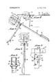
- FIG, 1 is a view illustrating one manner of utilization of the invention
- FIG. 2 is a view illustrating another manner of utilization of the invention wherein the sign is supported directly by the supporting leg in a vertical position;
- FIG. 3 is a view showing the sign with the supporting leg collapsed about the handle and with the handle in a vertical position
- FIG. 4 is a detailed view illustrating a pivoted joint between the handle and supporting leg
- FIG. 5 is a sectional view taken along the line 55 of FIG. 4.
- numeral 10 designates a rectangular sign of suitable size which may be made of any preferred material such as plastic, wood, or otherwise.
- the sign has the word Stop imprinted on one side and the word Slow imprinted on the opposite side.
- Numeral 12 device which overcomes all of the drawbacks and defi- I ciencies as referred to in the foregoing as well as providing a number of other significant advantages as will be pointed out.
- a preferred exemplary form of the invention as describedin detail herein, it takes the form of a sign having a laterally extending handle of appropriate length for the purpose with a hand grip at the end of the handle.
- a supporting leg pivoted or hinged to the handle Adjacent to the sign is provided a supporting leg pivoted or hinged to the handle so as to adapt the device to various forms of utilization.
- the object is realizedlthat the sign can be held in the most effective position for serving its purpose of giving warning while the user holds it in a safe position at a distance from the sign itself.
- the effort required to use the sign is minimized by way of the supporting leg which supports the sign at a position adjacent to it. The user then merely has to stabilize it and furthermore can very easily automate it by oscillating it about its pivot, the effort required to do this being minimal.
- the supporting leg is pivoted or collapsible so that it can be folded against the handle either for storage or transportation or for then using the sign with the handle in a vertical position and supported from the ground.
- a hand grip 14 in the form of a bar having end parts suitably secured to the top side of the handle 12 and providing room so that it can be gripped or grasped either with one hand or two.
- Numeral 22 designates a supporting leg which may be made of any suitable material and it may be made from bar stock like the handle 12 or it may be simply a strip of plastic, wood or metal. At its lower end a supporting end 22 is bifurcated having two diverging parts as designated at 24 and 26.
- the supporting leg has pivotal or hinged attachment to the handle 12, as shown more in detail in FIGS. 4 and 5.
- FIG. 5 attached to the sides of the handle 12 by welding, soldering or otherwise, are two bracket pieces 30and 32 which form a yoke.
- the upper end of the supporting end 22 is pivoted between the bracket pieces 30 and 32 by means of a pivot shaft 36 which is held in place by cotter pins 38 and 40.
- the supporting leg 22 is rotatable about its hinge or pivot so that it can be folded or collapsed into a position as shown in FIG. 3.
- a stop member 44 is provided as may be seen particularly in FIG. 4 secured as by welding or the like to the bracket pieces 30 and 32 in a position which limits the angular or rotative movement of the supporting leg 22.
- the stop member 44 is positioned to limit the angular movement of the supporting leg 22 so that it will be retained in substantially a 90 position relative to the handle 12 as shown in FIG. 1.
- FIG. 2 illustrates a position wherein a user grasps the grip 14 with tensions 24 and 26 resting on the street so that the entire weight of the unit is supported. Little or no effort is required by the user since he does not have to hold the weight of the assembly but only has to stabilize it and if desired can oscillate the handle to give it dy-' namic moving effect to the sign and thereby enhance the warning qualities.
- FIG. 1 illustrates a utilization of the invention which is a static utilization not requiring the presence of a user at all.
- the handle 12 is simply allowed to have its end rest on the ground or pavement as shown so that it is tilted with the sign in the position shown but yet readily visible and readable.
- the sign can be left in this position at any place or area where it is necessary or desirable that a warning or signal be displayed.
- FIG. 3 illustrates the sign with the supporting leg 22 folded or collapsed against the handle 12.
- the handle 12 is in a vertical position and in this position its end may be stuck into the ground or otherwise supported so that the handle is vertical.
- the 7 Slow sign as previously explained is positioned transversely with respect to the handle 12 so that the sign as a whole appears as in FIG. 3.
- the hinge stop 44 acts to hold the supporting leg 22 in substantially a ninety-degree position as shown.
- said legend being disposed in a normal reading position for oncoming motorists when said signal device occupies said position of use.
- a signal device including:
- said ground engaging leg end is relatively wide to permit placement of said signal device in a stable position wherein said latter leg and bar ends rest on the ground with said device in an upright position.
- a signal device according to claim 2 wherein:
- said device includes a second sign rigidly fixed to said one bar end and bearing a second warning legend
- saidsignal device in said retracted position having said bar upright with said other bar end lowermost for resting on the ground and said support leg lies flat against said bar
- said second sign legend being disposed in a normal reading position for oncoming motorists when said signal device occupies said retracted position of use.
Landscapes
- Engineering & Computer Science (AREA)
- Physics & Mathematics (AREA)
- General Physics & Mathematics (AREA)
- Theoretical Computer Science (AREA)
- Architecture (AREA)
- Civil Engineering (AREA)
- Structural Engineering (AREA)
- Road Signs Or Road Markings (AREA)
Abstract
A manually maneuverable sign having a laterally extending handle with a hand grip and a pivoted supporting leg attached to the handle adjacent to the sign.
Description
United States Patent 11 1 Lapham et al.
1 1 Feb. 25, 1975 FLAGMANSIGNAL DEVICE [75] Inventors: James O. Lapham, San Dimas;
Richard C. Atha, Hacienda Heights,
both of Calif. [73] Assignee: James O Lapham, Covina, Calif. 22 Filed: Nov. 30, 1973 211 Appl. 116.; 420,450
51 1m. (:1. G09f 7/18, EOlf 9/10 [58] Field Of Search 116/173, 174, 175, 63 R, 116/63 P;|248/472; 246/473 477, 488; 40/125 11 [56] References Cited UNITED STATES PATENTS 1,653,494 12/1927 Carter 246/477 l/1964 Keats 40/125 l-I 7/1972 Sayles 40/125 X FOREIGN PATENTS OR APPLICATIONS 398,256 11/1970 France 116/175 60,478 2/1939 Norway....; 248,157 6/1912 Germany 246/477 Primary Examiner-Charles A. Ruehl Assistant ExaminerDaniel M. Yasich Attorney, Agent, or Firm-Boniard I. Brown [57] ABSTRACT A manually maneuverable sign having a laterally extending handle with a hand grip and a pivoted supporting leg attached to the handle adjacent to the sign.
3 Claims, 5 Drawing Figures 1 FLAGMAN SIGNAL DEVICE SUMMARY OF THE INVENTION The invention is a manually maneuverable sign or signal device adapted for use by personnel such as flagmen, individuals controlling traffic at intersections or by any person controlling traffic or other movements in the vicinity of construction sites or otherwise.
Persons other than traffic officials or uniformed officers are frequently called upon to direct or control traffic at intersections or in the vicinity of construction sites or areas where streets are being worked on to control traffic to prevent accidents that might otherwise arise by reason of areas being blocked off, closed or otherwise. Typically persons who undertake to control traffic at intersections, as for. example, individuals who assist children in crossing busy streets on their way to school or otherwise use an ordinary hand sign resembling a paddle with a short handle with the word Stop printed on it. Similarly workmen in the vicinity of construction sites -or on streets where street work is being done undertake to control traffic either by way of a small-hand flag or without any signalling device at all. Such forms of warning or signalling devices are primitive or are less than adequate for their purpose. This is particularly true since the individual manipulating the warning or traffic device is frequently himself subjected to danger. This is true because in effectively usesuch warning or signalling device, the user himself has to position himself in the path of the moving traffic or too closeto it to be safe. Motorists tend in fact not to pay the same degree of attention to such'an unofficial individual directing traffic asthey would to a uniformed officer typically armed and wearing white gloves and thus accoutered with the symbols of authority which the unofficial individual is lacking. Furthermore, such primitive signalling or warning devices as are referred to may be heavy, and not easy to maneuver or manipulate.
The herein invention provides a warning or signalling parent from the following detailed description and annexed drawings wherein:
FIG, 1 is a view illustrating one manner of utilization of the invention;
FIG. 2 is a view illustrating another manner of utilization of the invention wherein the sign is supported directly by the supporting leg in a vertical position;
FIG. 3 is a view showing the sign with the supporting leg collapsed about the handle and with the handle in a vertical position;
FIG. 4 is a detailed view illustrating a pivoted joint between the handle and supporting leg;
FIG. 5 is a sectional view taken along the line 55 of FIG. 4.
Referring now more in detail to the various figures of the drawings which-illustrate a preferred exemplary form of the invention, numeral 10 designates a rectangular sign of suitable size which may be made of any preferred material such as plastic, wood, or otherwise. In the form of the invention shown, the sign has the word Stop imprinted on one side and the word Slow imprinted on the opposite side. Numeral 12 device which overcomes all of the drawbacks and defi- I ciencies as referred to in the foregoing as well as providing a number of other significant advantages as will be pointed out. In a preferred exemplary form of the invention as describedin detail herein, it takes the form of a sign having a laterally extending handle of appropriate length for the purpose with a hand grip at the end of the handle. Adjacent to the sign is provided a supporting leg pivoted or hinged to the handle so as to adapt the device to various forms of utilization. Firstly, the object is realizedlthat the sign can be held in the most effective position for serving its purpose of giving warning while the user holds it in a safe position at a distance from the sign itself. Furthermore, the effort required to use the sign is minimized by way of the supporting leg which supports the sign at a position adjacent to it. The user then merely has to stabilize it and furthermore can very easily automate it by oscillating it about its pivot, the effort required to do this being minimal. Further, the supporting leg is pivoted or collapsible so that it can be folded against the handle either for storage or transportation or for then using the sign with the handle in a vertical position and supported from the ground.
All of the foregoing objects are readily achieved by the article of the invention. Many further objects and additional advantages of the invention will become apdesignates a handle which in the exemplary form of the invention is a long bar of hollow square cross-section which may be metal, plastic, or otherwise. The Sign 10 is secured to the handle 12 by any suitable means such as rivets, bolts, adhesion or otherwise.
At the end of the handle 12 is a hand grip 14 in the form of a bar having end parts suitably secured to the top side of the handle 12 and providing room so that it can be gripped or grasped either with one hand or two.
In the exemplary form of the invention two rectangular signs are shown, one having the word Stop on it being parallel to the handle 12 and the other one having the word Slow on it designated at 16 being transverse to the handle 12.
Numeral 22 designates a supporting leg which may be made of any suitable material and it may be made from bar stock like the handle 12 or it may be simply a strip of plastic, wood or metal. At its lower end a supporting end 22 is bifurcated having two diverging parts as designated at 24 and 26. The supporting leg has pivotal or hinged attachment to the handle 12, as shown more in detail in FIGS. 4 and 5. Referring to FIG. 5 attached to the sides of the handle 12 by welding, soldering or otherwise, are two bracket pieces 30and 32 which form a yoke. The upper end of the supporting end 22 is pivoted between the bracket pieces 30 and 32 by means of a pivot shaft 36 which is held in place by cotter pins 38 and 40. The supporting leg 22 is rotatable about its hinge or pivot so that it can be folded or collapsed into a position as shown in FIG. 3. However, a stop member 44 is provided as may be seen particularly in FIG. 4 secured as by welding or the like to the bracket pieces 30 and 32 in a position which limits the angular or rotative movement of the supporting leg 22. The stop member 44 is positioned to limit the angular movement of the supporting leg 22 so that it will be retained in substantially a 90 position relative to the handle 12 as shown in FIG. 1.
The great versatility, adaptability and utility of the article is illustrated in FIGS. 1, 2 and 3. FIG. 2 illustrates a position wherein a user grasps the grip 14 with tensions 24 and 26 resting on the street so that the entire weight of the unit is supported. Little or no effort is required by the user since he does not have to hold the weight of the assembly but only has to stabilize it and if desired can oscillate the handle to give it dy-' namic moving effect to the sign and thereby enhance the warning qualities.
FIG. 1 illustrates a utilization of the invention which is a static utilization not requiring the presence of a user at all. In this utilization the handle 12 is simply allowed to have its end rest on the ground or pavement as shown so that it is tilted with the sign in the position shown but yet readily visible and readable. The sign can be left in this position at any place or area where it is necessary or desirable that a warning or signal be displayed. j
FIG. 3 illustrates the sign with the supporting leg 22 folded or collapsed against the handle 12. As shown in FIG. 3, the handle 12 is in a vertical position and in this position its end may be stuck into the ground or otherwise supported so that the handle is vertical. The 7 Slow sign as previously explained is positioned transversely with respect to the handle 12 so that the sign as a whole appears as in FIG. 3.
In the positions of FIGS. 1 and 2 the hinge stop 44 acts to hold the supporting leg 22 in substantially a ninety-degree position as shown.
From the foregoing those skilled in the art will readily understand the nature and utilization of the invention and the manner in which it achieves and realizes all of the objects and advantages as set forth in the foregoing as well as the'many additional advantages that are apparent from the detailed description.
The foregoing disclosure is representative of a preferred form of the invention and is intended to be interpreted in an illustrative rather than a limiting sense, the invention to be accorded the full scope of the claims appended hereto.
a warning signal bearing a warning legend,
a long bar rigidly fixed at one end to said sign with the longitudinal axis of the bar substantially parallel to the plane of the sign and having a handle at the other end adapted to be manually held,
a support leg having a ground engaging end,
means pivotally joining the other end of said leg to said bar at a position between said sign and handle and close to said sign on a pivot axis substantially normal to said sign plane and bar axis for selective swinging of said leg between an extended position wherein the leg is extending transversely of said bar to provide a pivotal ground support for supporting said signal device held in a position of use wherein said bar is generally horizontal and a retracted position wherein said leg rests against said bar with its ground engaging end adjacent said handle, and
said legend being disposed in a normal reading position for oncoming motorists when said signal device occupies said position of use.
v 2. A signal device according to claim 1, including:
coacting stop means-on said bar and support leg for limiting swinging of said leg from said retracted position to said extended position, and
said ground engaging leg end is relatively wide to permit placement of said signal device in a stable position wherein said latter leg and bar ends rest on the ground with said device in an upright position.
3. A signal device according to claim 2 wherein:
said device includes a second sign rigidly fixed to said one bar end and bearing a second warning legend,
saidsignal device in said retracted position having said bar upright with said other bar end lowermost for resting on the ground and said support leg lies flat against said bar,
said second sign legend being disposed in a normal reading position for oncoming motorists when said signal device occupies said retracted position of use.
Claims (3)
1. A highway flagman signal device comprising: a warning signal bearing a warning legend, a long bar rigidly fixed at one end to said sign with the longitudinal axis of the bar substantially parallel to the plane of the sign and having a handle at the other end adapted to be manually held, a support leg having a ground engaging end, means pivotally joining the other end of said leg to said bar at a position between said sign and handle and close to said sign on a pivot axis substantially normal to said sign plane and bar axis for selective swinging of said leg between an extended position wherein the leg is extending transversely of said bar to provide a pivotal ground support for supporting said signal device held in a position of use wherein said bar is generally horizontal and a retracted position wherein said leg rests against said bar with its ground engaging end adjacent said handle, and said legend being disposed in a normal reading position for oncoming motorists when said signal device occupies said position of use.
2. A signal device according to claim 1, including: coacting stop means on said bar and support leg for limiting swinging of said leg from said retracted position to said extended position, and said ground engaging leg end is relatively wide to permit placement of said signal device in a stable position wherein said latter leg and bar ends rest on the ground with said device in an upright position.
3. A signal device according to claim 2 wherein: said device includes a second sign rigidly fixed to said one bar end and bearing a second warning legend, said signal device in said retracted position having said bar upright with said other bar end lowermost for resting on the ground and said support leg lies flat against said bar, said second sign legend being disposed in a normal reading position for oncoming motorists when said signal device occupies said retracted position of use.
Priority Applications (1)
| Application Number | Priority Date | Filing Date | Title |
|---|---|---|---|
| US420450A US3867775A (en) | 1973-11-30 | 1973-11-30 | Flagman signal device |
Applications Claiming Priority (1)
| Application Number | Priority Date | Filing Date | Title |
|---|---|---|---|
| US420450A US3867775A (en) | 1973-11-30 | 1973-11-30 | Flagman signal device |
Publications (1)
| Publication Number | Publication Date |
|---|---|
| US3867775A true US3867775A (en) | 1975-02-25 |
Family
ID=23666528
Family Applications (1)
| Application Number | Title | Priority Date | Filing Date |
|---|---|---|---|
| US420450A Expired - Lifetime US3867775A (en) | 1973-11-30 | 1973-11-30 | Flagman signal device |
Country Status (1)
| Country | Link |
|---|---|
| US (1) | US3867775A (en) |
Cited By (10)
| Publication number | Priority date | Publication date | Assignee | Title |
|---|---|---|---|---|
| FR2609199A1 (en) * | 1986-12-26 | 1988-07-01 | Feuvray Alain | Portable anti-wind, diversion, commercial advertising and road sign device |
| EP0348577A1 (en) * | 1988-03-25 | 1990-01-03 | Alain Feuvray | Portable, wind-resistant and mobile road sign or advertising device |
| WO1990000295A1 (en) * | 1988-06-27 | 1990-01-11 | Alain Feuvray | A portable wind-resistant and flexible road sign |
| US4905391A (en) * | 1988-11-22 | 1990-03-06 | Dillon George D | Portable highway sign stand |
| US5097790A (en) * | 1990-12-21 | 1992-03-24 | Graham-Migletz Enterprises, Inc. | Flagger gate for roadway construction sites |
| US5305975A (en) * | 1992-11-06 | 1994-04-26 | Douglass Charles L | Flagging apparatus and method |
| US20050280554A1 (en) * | 2004-06-21 | 2005-12-22 | Frank Chan | Safety arrow tool for pedestrian |
| US20090084304A1 (en) * | 2007-10-01 | 2009-04-02 | William Henry Hatcher | Emergency safety reflector for automotive vehicles |
| US20090084009A1 (en) * | 2007-10-01 | 2009-04-02 | Jon Vandergriff | Portable changeable illuminated display for vehicles and other miscellaneous purposes |
| US8144030B1 (en) * | 2008-03-10 | 2012-03-27 | Lipke Douglas D | Personal signal device with automatic switching based on orientation |
Citations (3)
| Publication number | Priority date | Publication date | Assignee | Title |
|---|---|---|---|---|
| US1653494A (en) * | 1927-03-16 | 1927-12-20 | Carter Franklin Walden | Railway track signal |
| US3119588A (en) * | 1962-10-05 | 1964-01-28 | John B Keats | Portable sign |
| US3675613A (en) * | 1970-05-28 | 1972-07-11 | Louis F Sayles | Collapsible signal assembly |
-
1973
- 1973-11-30 US US420450A patent/US3867775A/en not_active Expired - Lifetime
Patent Citations (3)
| Publication number | Priority date | Publication date | Assignee | Title |
|---|---|---|---|---|
| US1653494A (en) * | 1927-03-16 | 1927-12-20 | Carter Franklin Walden | Railway track signal |
| US3119588A (en) * | 1962-10-05 | 1964-01-28 | John B Keats | Portable sign |
| US3675613A (en) * | 1970-05-28 | 1972-07-11 | Louis F Sayles | Collapsible signal assembly |
Cited By (10)
| Publication number | Priority date | Publication date | Assignee | Title |
|---|---|---|---|---|
| FR2609199A1 (en) * | 1986-12-26 | 1988-07-01 | Feuvray Alain | Portable anti-wind, diversion, commercial advertising and road sign device |
| EP0348577A1 (en) * | 1988-03-25 | 1990-01-03 | Alain Feuvray | Portable, wind-resistant and mobile road sign or advertising device |
| WO1990000295A1 (en) * | 1988-06-27 | 1990-01-11 | Alain Feuvray | A portable wind-resistant and flexible road sign |
| US4905391A (en) * | 1988-11-22 | 1990-03-06 | Dillon George D | Portable highway sign stand |
| US5097790A (en) * | 1990-12-21 | 1992-03-24 | Graham-Migletz Enterprises, Inc. | Flagger gate for roadway construction sites |
| US5305975A (en) * | 1992-11-06 | 1994-04-26 | Douglass Charles L | Flagging apparatus and method |
| US20050280554A1 (en) * | 2004-06-21 | 2005-12-22 | Frank Chan | Safety arrow tool for pedestrian |
| US20090084304A1 (en) * | 2007-10-01 | 2009-04-02 | William Henry Hatcher | Emergency safety reflector for automotive vehicles |
| US20090084009A1 (en) * | 2007-10-01 | 2009-04-02 | Jon Vandergriff | Portable changeable illuminated display for vehicles and other miscellaneous purposes |
| US8144030B1 (en) * | 2008-03-10 | 2012-03-27 | Lipke Douglas D | Personal signal device with automatic switching based on orientation |
Similar Documents
| Publication | Publication Date | Title |
|---|---|---|
| US3867775A (en) | Flagman signal device | |
| US3380428A (en) | Traffic guide post | |
| US3520235A (en) | Collapsible road marker | |
| US4548379A (en) | Compact sign and stand | |
| US4593879A (en) | Compact sign stand | |
| US4777751A (en) | Portable illuminated signal person station | |
| US2869504A (en) | Emergency road sentinel | |
| US3950874A (en) | Universal mounting bracket for signs | |
| US2646638A (en) | Traffic warning and directing signal | |
| US6003256A (en) | Roll-up stop/slow sign | |
| US3738309A (en) | Collapsible warning device | |
| US2002248A (en) | Traffic sign | |
| US4232466A (en) | Collapsible display frame | |
| US3792678A (en) | Emergency warning sign with readily collapsible frame | |
| US3085546A (en) | Traffic sign | |
| US2834133A (en) | Highway sign | |
| US5339765A (en) | Direction indicating traffic barricade | |
| FR2807453B1 (en) | FOLDABLE SUPPORT DEVICE FOR SIGNALING PANEL | |
| US2551831A (en) | Railway signal | |
| CH328624A (en) | Road sign | |
| US2783566A (en) | Collapsible work sign | |
| JPH0137309Y2 (en) | ||
| DE4439219C1 (en) | Road traffic safety system | |
| JP2656436B2 (en) | Road signs | |
| CN204491443U (en) | A kind of movable sign vehicle on road |