US3858953A - Towel dispenser - Google Patents
Towel dispenser Download PDFInfo
- Publication number
- US3858953A US3858953A US401982A US40198273A US3858953A US 3858953 A US3858953 A US 3858953A US 401982 A US401982 A US 401982A US 40198273 A US40198273 A US 40198273A US 3858953 A US3858953 A US 3858953A
- Authority
- US
- United States
- Prior art keywords
- towel
- housing
- wheeling
- free
- clean
- Prior art date
- Legal status (The legal status is an assumption and is not a legal conclusion. Google has not performed a legal analysis and makes no representation as to the accuracy of the status listed.)
- Expired - Lifetime
Links
- 230000007246 mechanism Effects 0.000 claims abstract description 290
- 230000005484 gravity Effects 0.000 claims description 20
- 230000004044 response Effects 0.000 abstract description 2
- 230000009471 action Effects 0.000 description 5
- 239000004744 fabric Substances 0.000 description 5
- 238000013459 approach Methods 0.000 description 3
- 238000010276 construction Methods 0.000 description 3
- 230000006872 improvement Effects 0.000 description 3
- 238000003466 welding Methods 0.000 description 2
- 230000002452 interceptive effect Effects 0.000 description 1
- 238000000034 method Methods 0.000 description 1
- 230000004048 modification Effects 0.000 description 1
- 238000012986 modification Methods 0.000 description 1
- 230000008520 organization Effects 0.000 description 1
- 239000007787 solid Substances 0.000 description 1
Images


Classifications
-
- A—HUMAN NECESSITIES
- A47—FURNITURE; DOMESTIC ARTICLES OR APPLIANCES; COFFEE MILLS; SPICE MILLS; SUCTION CLEANERS IN GENERAL
- A47K—SANITARY EQUIPMENT NOT OTHERWISE PROVIDED FOR; TOILET ACCESSORIES
- A47K10/00—Body-drying implements; Toilet paper; Holders therefor
- A47K10/24—Towel dispensers, e.g. for piled-up or folded textile towels; Toilet-paper dispensers; Dispensers for piled-up or folded textile towels provided or not with devices for taking-up soiled towels as far as not mechanically driven
- A47K10/28—Towel dispensers, e.g. for piled-up or folded textile towels; Toilet-paper dispensers; Dispensers for piled-up or folded textile towels provided or not with devices for taking-up soiled towels as far as not mechanically driven dispensing a clean part and taking-up a soiled part, e.g. using rolls; with dispensers for soap or other detergents; with disinfecting or heating devices
Definitions
- a continuous towel dispenser cabinet includes a housing within which are disposed a towel dispensing mechanism and a towel take-up mechanism, time-stop mechanism in the housing for stopping the dispensing mechanism and the take-up mechanism after dispensing a predetermined length of clean towel and thereafter holding the mechanisms in the stopped condition for a predetermined period of time, and free-wheeling mechanism within the housing and having a towel ,dispcnsing condition wherein the time-stop mechanism is normally operative and a freewheeling condition wherein'the time-stop mechanism is prevented from operation so that an attendant can continuously withdraw clean towel from the cabinet to facilitate servicing of the towel dispenser, the free-wheeling mechanism being automatically operable in response to' opening a door on the housing in certain forms of the invention and being manually operable in another.
- the present invention relates generally to improvements in towel dispensing cabinets, and specifically to improvements in the operation of cloth towel dispensing cabinets of the continuous type incorporating timestop mechanism which limits the amount of clean towel dispensed during each dispensing cycle and which provides a predetermined time interval between dispensing cycles.
- Clean towel dispensing cabinets of the continuous type incorporating time-stop mechanisms therein which are well known in the prior art. Difficulty has been experienced in servicing such towel dispensing cabinets when a small amount of clean towel is still in the clean towel supply at the time of servicing. Servicing of prior cabinets has required the service man to remove the clean towel from the clean towel supply by operating the dispensing mechanism under the control of the timestop mechanism using the normal dispensing cycle, which operation has been laborious and time consuming.
- the present invention provides a dispensing cabinet for continuous cloth toweling which permits easy removal of the last portion of clean towel from'the clean towel supply during servicing of the towel dispensing cabinet.
- a towel dispenser of the continuous loop type including a housing having associated therewith a loop of towel that extends along an exit path from a clean towel supply within the housing into an exposed use position exteriorly of the housing accessible to a user and thence along a return path to a soiled towel storage position within the housing, towel dispensing mechanism in the housing for dispensing the clean towel and take-up mechanism in the housing for taking up the soiled towel, time stop mechanism in the housing for stopping the dispensing mechanism and the take-up mechanism ater the dispensing of a predetermined length of clean towel and thereafter holding the mechanisms in the stopped condition for a predetermined period of time, and a free-wheeling mechanism within the housing having a towel dispensing condition wherein the time-stop mechanism is normally operative and a free-wheeling condition wherein the time-stop mechanism is prevented from operation, whereby when the free-wheeling mechanism is placed in the free-wheeling condition thereof an attendant can
- the time-stop mechanism is of the vacuum cup type having an air passage connected with the interior of the vacuum cup to control the release thereof after movement to the stopped position thereof, and the free-wheeling mechanism is a member movable into a position to prevent engagement of the vacuum cup in the stopped position thereof.
- Yet another object of the invention is to provide a towel dispenser of the type set forth, wherein the freewheeling mechanism is moved into its free-wheeling position by opening a cover for the towel dispenser.
- another object of the invention is to'provide a towel dispenser of the type set forth, wherein the free-wheeling mechanism is moved by gravity to the free-wheeling position thereof upon movement of the cover to the towel servicing position thereof.
- Still another object of the invention is to provide a towel dispenser of the type set forth wherein the timestop mechanism is pivotally mounted on the dispenser housing and pivotal between a towel dispensing posi tion wherein the time-stop mechanism is normally operative and free-wheeling position wherein the time stop mechanism is prevented from operation, and a free-wheeling bracket is provided within the housing adjacent to the time-stop mechanism when the timestop mechanism is pivoted to the free-wheeling position thereof, the cover of the housing when closed holding the time-stop mechanism in the towel dispensing position thereof and opening of the door to provide for towel servicing permitting the time-stop mechanism to be pivoted to the free-wheeling position thereof.
- FIG. 1 is a diagrammatic view in vertical section with certain parts broken away of a first embodiment of a towel dispenser constructed in accordance with and embodying the features of the present invention
- FIG. 2 is a view similar to FIG. 1 showing the parts of the towel dispenser in the towel servicing position thereof;
- FIG. 3 is an enlarged view in vertical section similar to FIG. 1 and showing the details of the time-stop mechanism and the free-wheeling mechanism thereof, the parts being shown in the towel dispensing positions;
- FIG. 4 is a view of the upper portion of the towel dispenser of FIG. 3 with the parts shown in the towel servicing position thereof;
- FIG. 5 is a view similar to FIG. 3 showing a second preferred embodiment of a towel dispenser constructed in accordance with and embodying the features of the present invention, the parts thereof being shown in the towel dispensing positions thereof;
- FIG. 6 is a view of the lower portion of FIG. 5 show ing the parts in the towel servicing position thereof;
- FIG. 7 is a view in horizontal section along the line 7-7 of FIG. 5;
- FIG. 8 is a plan view of the free-wheeling bracket of i the towel dispenser of FIGS. 5 to 7;
- FIG. 9 is a view in section along the line 9-9 of FIG. 8;
- FIG. 10 is a perspective view of a third embodiment of a towel dispenser constructed in accordance with and embodying the features of the present invention.
- FIG. 11 is an enlarged view in vertical section along the line 1111 of FIG. 10;
- FIG. 12 is a perspective view of the cover of the towel dispenser of FIG. 10;
- FIG. 13 is a plan view with certain parts broken away of the towel dispenser of FIG. 10;
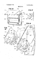
- FIG. 14 is a perspective view of a fourth embodiment of a towel dispenser constructed in accordance with and embodying the features of the present invention, the cover of the cabinet being open to disclose the interior mechanisms thereof;
- FIG. 15 is an enlarge sideview with certain portions broken away illustrating the time-stop mechanism of the towel dispenser of FIG. 14, the parts being shown in the towel dispensing positions thereof;
- FIG. 16 is a view illustrating a portion of FIG. 15 and showing the parts in the towel servicing positions thereof;
- FIG. 17 is an enlarged fragmentary view illustrating the position of the free-wheeling bracket and the suction cups of the time-stop mechanism in the freewheeling positions thereof.
- FIGS. 1 to 4 of the drawings there is shown a towel dispenser 100 which is a first preferred embodiment of a towel dispenser made in accordance with and embodying the principles of the present invention.
- the towel dispenser 100 includes an enclosed housing 101 having a rear wall 102 adapted to be disposed against a suitable vertical support surface, and a top wall 103 integral with the upper edge thereof and a bottom wall 105 integral with the lower edge thereof, the top wall 103 having a flange 104 that extends downwardly along a portion of the rear wall 102 as illustrated best in FIGS. 3 and 4. Also affixed on the rear wall 102 is a fixed towel breaker assembly including an upper fixed towel breaker 106 and a lower fixed towel breaker 107. Disposed on the vertically extending edges of the rear wall 102 and joining the top wall 103 and the bottom wall 105 are two generally parallel side walls 108.
- a lower cover or door 110 Disposed at the lower portion of the towel dispenser 100 is a lower cover or door 110 which is illustrated as formed integral with a towel bed generally designated by the numeral 11 and including a front wall 112, a bottom wall 113 and a rear wall 114 all formed integral, and a pair of side walls 115.
- the combination of the lower cover 110 and 111 is pivoted on the housing side walls 108 as at 116 for pivotal movement between the positions illustrated in FIGS. 1 and 2 of the drawings.
- the upper edge of the rear wall 114 carries a movable towel breaker 117 which in the use position illustrated in FIGS. 1 and 3 is disposed between the fixed towel breakers 106 and 107, the towel breakers cooperating to smooth the used toweling in the usual manner.
- a spring 118 interconnecting the towel bed 111 and the housing rear wall 102 to urge the towel bed 111 and the lower cover 110 to the towel dispensing position illustrated in FIG. 1.
- the housing 101 is also provided with an upper cover or door 120 which is hingedly connected to the remainder of the housing 101 by a pair of hinge plates 121 which are pivotally mounted on the housing side walls 108 as at 122, the upper cover 120 being fixedly secured as by welding to the hinge plate 121 so that the upper cover 120 can move between a towel dispensing position illustrated in FIG. 1 and a clean towel servicing position illustrated in FIG. 2.
- Interconnecting the towel bed 111 and the upper cover 120 is a hinge arm 125 pivoted to the hinge plate 121 as at 126 and having an elongated support 127 in the other end thereof which receives a pin 128 mounted on the towel bed 111. Movement of the lower cover 110 to the clean towel servicing position illustrated in FIG. 2 through action of the hinge arm 125 serves to open cover 120, whereby movement of a single member from the towel dispensing position of FIG. 1 to the clean towel servicing position of FIG. 2 moves all of the parts as illustrated.
- a towel dispensing mechanism is mounted on the side plates 130 and includes a front drive roller 136 which typically has a sandpaper covering thereon to improve engagement with the cloth towel being dispensed, and a pinch roller 137 also provided with a sandpaper covering.
- the front drive roller 136 also carries a drive sprocket 138 for a purpose to be described more fully hereinafter.
- the take-up mechanism 140 includes a rear drive roller 141 having a sandpaper surface thereon and a take-up roller 144 on which the soiled toweling is wound.
- the rear drive roller 141 carries a drive sprocket 142 which engages a chain 143 and also engages the drive sprocket 138 on the dispensing mechanism 135.
- the dispensing mechanism 135 and the take-up mechanism 140 cooperate to feed towel from a clean towel supply 50 disposed in the towel bed 111 upwardly in an exit reach 51 between the front drive roller 136 and the pinch roller 137 and then downwardly through a slot between the covers 110 and 120 to an exposed use reach 52.
- the used towel is fed upwardly along a soiled reach 53, through the towel breakers 106, 107 and 117 and to a soiled towel roll 54 wound upon the take-up roller 144, the'surface of the soiled towel roll 54 being in engagement with the sandpaper surface on the rear drive roller 141.
- the time-stop mechanism 150 includes a stop latch 151 which is pivoted on the mechanism side plates 130 about the bolt 152, the stop latch 151 having a stop pawl 153 on the left hand end thereof as seen in the drawings.
- the stop latch 151 cooperates with a stop wheel 155 carried by the front drive roller 136, the stop wheel 155 being provided with five stop surfaces 156 around the periphery thereof that are adapted to engage with the stop pawl 153 on the stop latch 151.
- the stop latch 151 also carries a part-circular cam surface 157 which cooperates with a cam roller 159 carried by a cam arm 158, the cam arm 158 being mounted for rotationwith the rear drive roller 141, and more specifically rotates in a clockwise direction as viewed in the drawings.
- the time-stop mechanism 150 also includes an upper vacuum cup assembly 160 having a bracket 161 mounted on the adjacent mechanism side plate 130 by means of a screw 162 and a shoulder screw 167, the bracket 161 carrying a fixed vacuum cup 163 which has an opening centrally thereof communicating with a needle valve assembly 164 through which air can bleed to release the vacuum in the vacuum cup 163.
- the rate at which air is bled into the vacuum cup 163 can be adjusted by means-of an adjusting screw 165 operatively connected to the needle valve assembly 164'.
- a lower vacuum cup assembly 170 including a bracket 171 fixedly mounted on the adjacent mechanism side plate 130 and providing a journal for a vertically extending rod 172.
- the upper end of the rod 172 carries a second vacuum cup 173 disposed immediately below and-in alignment with but spaced from the vacuum cup 163, the lower end of the rod 172 being connected by a pivot 174 to the right hand end of the stop latch 151.
- a user grasps the exposed use reach 52 of the towel and pulls downwardly thereby to withdraw clean towel from the supply 50 and pass it along the reach 51 upwardly over the front drive roller 136. This serves to rotate the drive roller 136 in a clockwise direction and through a sprocket 138 and the chain 143 to drive the sprocket 142 and the cam arm 158. As the user approaches the end of a dispensing cycle, the cam roller 159 engages the cam surface 157 and pivots the stop latch 151 in a counterclockwise direction about its pivot 152.
- valve assembly 164 1 permits enough air to bleed into the area between the vacuum cups 163 and 173, the vacuum cups will release and the parts will move to the position illustrated in FIGS. 3 and 4, thus permitting a new dispensing cycle after the lapse of a predetermined time subsequent to completion of the prior dispensing cycle.
- time-stop mechanism 150 Further details of the construction and operation of the time-stop mechanism 150 will be found in the aforementioned U.S. Pat. No. 2,899.25] and in U.S. Pat. No. 2,940,720, issued to R. G. Birr on June 14, 1960, the disclosure of the patent is also incorporated herein by reference.
- a free-wheeling bracket 180 within the housing 101, the freewheeling bracket 180 being pivotally mounted upon the bracket 161 by means of a shoulder screw 167. More specifically, the freewheeling bracket 180 includes an arm 181 having an opening therein through which passes the shank of the shoulder screw 167. Disposed on the bracket 180 away from the. arm 181 is a side flange 182 which is positioned to engage a cam pin 129 on the hinge arm 125. Finally, the free-wheeling bracket 180 is provided with a lug 185 which can be disposed. between the vacuum cups 163 and 173 to prevent engagement thereof when the parts are in the position illustrated in FIG. 4. More specifically, the free-wheeling bracket 180 is shaped and arranged so that it falls under the urging of gravity from the position illustrated in FIG. 3 to the position illustrated in FIG. 4 when the flange 182 is released by the cam pin 129.
- the service man can :now continually withdraw clean towel from the supply 50 by pulling on the exposed reach 52, and although the vacuum cups 163 and 173 will'be periodically move-d to the position illustrated in FIG. 4, there will be no engagement thereof and no engagement of the stop pawl 153 with any of the stop surfaces 156, whereby any remaining supply of clean towel in the bed 111 can be quickly stripped therefrom to make way for a fulll roll of clean towel. Therefore, it will be appreciated that servicing of the dispenser 100 has been materially facilitated since the removal of the last portion of the clean towel from the bed 111 has been expedited.
- the towel dispenser 200 which is a second preferred embodiment of towel dispenser made in accordance with and embodying the principles of the present invention.
- the towel dispenser 200 includes an enclosed housing 201 having a rear wall 202 adapted to be disposed against a suitable vertical support surface, a top wall 203 integral with the upper edge thereof and a bottom wall 205 integral with the lower edge thereof, the top wall 203 having a flange 204 that extends downwardly along aportion of the rear wall 202 as illustrated in FIG. 5.
- a fixed towel breaker assembly including an upper fixed towel breaker 206 and a lower fixed towel breaker 207.
- Disposed on the vertically extending edges of the rear wall 202 and joining the top wall 203 and the bottom wall 205 are two generally parallel side walls 208.
- a lower cover 210 Disposed at the lower end of the towel dispenser 200 is a lower cover 210 that is hingedly connected to the bottom wall 205 as at 209. Further mounted within the housing 201 is a towel bed 211 hinged to the side walls 208 as at 212 and having side flanges 214 with slots 215 therein for a purpose to be described more fully hereinafter.
- the upper edge of the towel bed 211 carries a movable towel breaker 217 which in the use position illustrated in FIG. 5 is disposed between the fixed towel breakers 206 and 207, the towel breakers cooperating to smooth the used toweling in the usual manner.
- the housing 201 is also provided with an upper cover or door 220 which is hingedly connected to the remainder of the housing 201 by a pair of binge plates 221 that are pivotally mounted on the housing side walls 208 as at 222, the upper cover 220 being fixedly secured as by welding to the hinge plate 221 so that the upper cover 220 can move between a towel dispensing position illustrated in FIG. 5 and a clean towel servicing position permitting access to the interior of the housing 201. Also interconnecting one of the side walls 208 and the upper cover 220 is a spring 223 urging the upper cover 220 to the closed or towel dispensing position thereof.
- a towel dispensing mechanism 235 is mounted on the side plates 230 and includes a front drive roller 236 which typically has a sandpaper covering thereon to improve engagement with the cloth towel being dispensed, and a pinch roller 237.
- the take-up mechanism 240 includes a rear drive roller 241 having a sandpaper surface thereon and a take-up roller 244 journalled in slots 231 in the mechanism side plates 230, the take-up roller 244 receiving the soiled toweling which is wound thereon.
- the dispensing mechanism 235 and the take-up mechanism 240 cooperate to feed towel from a clean towel supply disposed in front of the towel bed 211 upwardly in an exit reach between the front drive roller 236 and the pinch roller 237 and then downwardly through a slot between the covers 210 and 220 to an exposed use reach.
- the used towel is fed upwardly through an opening 213 in the bottom wall 205 along a soiled towel reach, through the towel breakers 206, 207 and 217 and to a soiled towel roll wound upon the take-up roller 244, the surface of the soiled towel roll being in engagement with the sandpaper surface on the rear drive roller 24].
- the time-stop mechanism 250 includes an anti-reverse lever 251 which is pivoted on the mechanism side plates 230 about the pivot 252, the lever 251 having a pawl 253 on the left hand end thereof as seen in the drawings.
- the stop lever 251 cooperates with a stop cam 255 carried by the front drive roller 236, the stop cam 255 being provided with a stop surface 256 which is adapted to en gage the pawl 253.
- the lever 251 is also associated with an upper abutment 254 on the side plate 230 and a lower abutment 259 on the side plate 230 to limit the movement thereof, the right hand end of the stop lever 251 being weighted so that gravity tends continually to urge pivotal movement of the stop lever 251 in a clockwise direction.
- the time-stop mechanism 250 also includes an upper vacuum cup assembly 260 having a bracket 261 fixedly mounted on the adjacent mechanism side plate-230 by means of screws 262, the bracket 261 carrying a fixed vacuum cup 263 which has an opening centrally thereof communicating with a needle valve assembly 264 through which air can bleed to release the vacuum in the vacuum cup 263.
- the rate at which air is bled into the vacuum cup 263 can be adjusted by means of an adjusting screw 265 operatively connected to the needle valve assembly 264.
- a lower vacuum cup assembly 270 including a slide 271 mounted in ways provided by the bracket 261 cooperating with the adjacent mechanism side plate 230.
- the lower end of the slide 271 carries a flange 272 upon which is mounted a second vacuum cup 273 disposed immediately below and in vertical alignment with but spaced from the vacuum cup 263.
- the upper end of the slide 271 carries a lug 268 limiting downward travel of the slide 271 anda stop surface 269 engageable with a stop surface 266 on the stop cam 255.
- the slide 271 is connected by a pin 274 to the lower end of a first link 275 having an elongated slot 276 therein which receives therethrough a pin 258 fixedly mounted on the stop cam 255.
- the pin 258 also engages a second link 277, and more specifically engages in a slot 278 therein.
- a spring 279 interconnects the end of the second link 277 and the adjacent mechanism side plate 230 tohold the parts in the position illustrated in FIG. 5.
- a user grasps the exposed reach of towel and pulls downwardly thereby to withdraw clean towel from the supply in the bed 211 and pass it upwardly over the front drive roller 236.
- This serves to rotate the drive roller 236 in a clockwise direction and likewise drives the stop cam 255 in a clockwise direction carrying with it the pin 258 and the attached parts.
- the pin 258 reaches its highest point of travel above the axis of the front drive roller 236, the slide 271 is raised to its uppermost position and the movable vacuum cup 273 engages the fixed vacuum cup 263.
- the balance of the op eration of the time-stop mechanism 250 is as described in U.S. Pat. No. 2,834,645 referred to above.
- each of the guide arms 28-1 is mounted for sliding movement inwardly and outwardly with respect to the housing 201 and carries on the rear thereof an inturned flange 282 that extends through the slot 215 in the adjacent flange 214 on the towel bed 211.
- the free-wheeling bracket 280 is mounted on the right hand guide arm 281 when the cabinet 200 is viewed from the front, the bracket 280 including a lug 285 disposed substantially normal to the guide arm 281 and an integral flange 286 which lies along the guide arm 281 and is fixedly secured theretoas by spot welds 287.
- the lug 285 is in position so that when auser inserts his hand through the opening 213 and pushes the pivoted towel bed 211 forwardly, the lug 285 is moved between the suction cups 263 and 273 as illustrated in FIG. 6 of the drawings. Accordingly, it will be appreciated that the freewheeling bracket 280 and the lug 285 thereof is manually shiftable between'a towel dispensing position illustrated in FIG. of the drawings and a towel servicing position illustrated in FIG. 6 of the drawings.
- the service man can now continually withdraw clean towel from the supply in the bed 211 by pulling the exposed reach, and although the vacuum cups 263 and 273 will be periodically moved toward the engaged position, there will be no engagement thereof due to the presence of the lug 285 therebetween, whereby any remaining supply of clean towel in the bed 211 can be quickly stripped therefrom to make way for a full roll of clean towel. Therefore the servicing of the dispenser 200 has been materially facilitated since the removal of the last portion of clean towel from the bed 211 has been expedited.
- One of the side walls 314 has a rectangular notch 317 therein for a purpose to be described more fully hereinafter.
- a clean towel receptacle 320 within which a supply of clean towel is stored.
- a towel dispensing mechanism 335 is mounted on the side plates 330 and includes a front drive roller 336 which typically has a sandpaper covering thereon to improve engagement with the cloth towel being dispensed, and a pinch roller 337 also pro vided with a sandpaper covering.
- a soiled towel take-up mechanism 340 is mounted within the housing 301 on the mechanism side plates 330.
- the take-up mechanism 340 includes a rear drive roller 341 having a sandpaper surface thereon and a take-up roller (not 7 shown) on which the soiled toweling is wound.
- the dispensing mechanism 335 and the take'up mechanism 340 cooperate to feed toweling from a clean towel supply disposed in the receptacle 320 upwardly between the front drive roller 336 and the pinch roller 337 and then downwardly'out of the bottom of the cover 310 to an exposed use reach 52 (see FIG. 10).
- the used towel is fed upwardly through towel breakers (not shown). to a soiled towel roll wound upon a take-up roller (not shown).
- the user grasps the exposed use reach 52 and pulls downwardly, thereby to pull towel from the receptacle 320 over the front drive roller 336 and around the pinch roller 337 to the exposed use reach 52.
- the above described dispensing mechanism 330 and the take-up mechanism 340 are described in detail in U.S. Pat. No. 2,889,251 mentioned above, the
- the time-stop mechanism 350 includes a stop latch 351 which is pivoted on the mechanism side plates 330 about the bolt 352, the stop latch 351 having a stop pawl 353 on the left hand end thereof as seen in the drawings.
- the stop latch 351 cooperates with a stop wheel 355 carried by the front drive roller 336, the stop wheel 355 being provided with five stop surfaces 356 around the periphery thereof that are adapted to engage with the stop pawl 353 on the stop latch 351.
- the stop latch 351 also carries a part-circular cam surface 357 which cooperates with a cam roller 359 carried by a cam arm 358, the cam arm 358 being mounted for rotation with the
- the time-stop mechanism 350 also includes an upper vacuum cup assembly 360 having a bracket 361 mounted on the adjacent mechanism side plate 330 by means of a screw 362 and a shoulder screw 367, the bracket 361 carrying a fixed vacuum cup 363 which has an opening centrally thereof communicating with a needle valve assembly 364 through which air can bleed to release thervacuum in the vacuum cup 363.
- the rate at which airis bled into the vacuum cup 363 can be adjusted by means of an adjusting screw 365 operatively connected to the needle valve assembly 364.
- a lower vacuum cup assembly 370 including a bracket 371 fixedly mounted on the adjacent mechanism side plate 330 and providing a journal for a vertically extending rod 372.
- the upper end of the rod 372 carries a second vacuum cup 373 disposed immediately below and in alignment with but spaced from the vacuum cup 363, the lowerend of the rod 372 being connected by a pivot 374 to the right hand end of the stop latch 351.
- a user grasps the exposed use reach 52 of the towel and pulls downwardly, thereby to withdraw clean towel from the receptacle 320 and pass it upwardly in front of the drive roller 336. This serves to rotate the drive roller 336 in a clockwise direction and through a sprocket chain (not shown) to drive the cam arm 358.
- the cam roller 359 engages the cam surface 357 and pivots the stop latch 351 in a counterclockwise direction about its pivot 352.
- Such movement immediately causes the stop latch 351 through the rod 372 to move the lower vacuum. cup 373 into engagement with the upper vacuum cup 363 and thus to hold the stop latch 351 in its counterclockwise position.
- Thestop pawl 353 at this time is spaced from the-next approaching stop surface 356, but continued movement of the clean towel into the use reach 52 serves to rotate the next stop surface 356 into engagement with the stop pawl 353, thus to stop further dispensing of clean towel.
- This additional movement of the parts also serves to rotate the cam roller 359 out of engagement with the cam surface 357 and essentially to the position illustrated in FIG. 11 of the drawings. So long as the vacuum cups 363 and 373 are engaged, it will be impossible to dispense further cleantowel.
- a free-wheeling bracket 380 within the housing 301, the free-wheeling bracket 380 being pivotally mounted on the bracket 361 by means of the shoulder screw 367.
- the opening bracket 380 includes a mounting arm 381 having an openin therein through which passes the shank of the shoulder screw 367.
- Disposed on the bracket 380 away from the arm 381 is a side flange 382 which is positioned in the notch 317 in the cover 310.
- free-wheeling bracket 380 is provided with a lug 385 which can be disposed between the vacuum cups 363 and 373 to prevent engagement thereof when the parts are in the position illustrated by dashed lines in FIG. 11. More specifically the free-wheeling bracket 380 is shaped and arranged so thatit falls by the urging of gravity from the position illustrated in solidlines in FIG. 11 to the position illustrated in dashed lines therein when the cover 310 is opened.
- the freewheeling bracket 380 is also held in its towel dispensing position illustrated by solid lines in FIG. 11. More specifically, the periphery of the notch 317 in the cover 310 engages the side flange 382 on the free-wheeling bracket 380 to hold it pivoted in a counterclockwise position such as to move the lug 385 out of the path of the lower vacuum cup 373. With the parts in these positions, the vacuum cups 363 and 373 operate in the normal manner, whe'reby the time-stop mechanism 350 in its entirety operates in the normal time-stop manner described above.
- a towel dispenser 400 which is a fourth preferred embodiment of a towel dispenser made in accordance with and embodying the principles of the present invention.
- the towel dispenser 400 includes an enclosed housing 401 adapted to be disposed against a suitable vertical support surface, and a bottom wall 405 integral with the lower edge thereof, and a pair of parallel side walls 406. Hingedly mounted on the upper edge of the rear wall 402 is a cover or door 410 that includes a front wall 412 and a upwardly sloping top wall 413. Disposed in the bottom of the housing 401 is a towel bed 411 for holding a supply of clean towel.
- a removable mechanism frame 420 that includes a pair of spaced apart mechanism side plates 430 joined by suitable cross structure (not shown).
- the housing 401 has fixedly secured therein forwardly extending supports 408 having notches 409 that pivotally suspend the removable mechanism frame 420 for pivoting between the solid line position and dashed line position illustrated in FIG. 15.
- the mechanism side plates 430 have mounted thereon the various operating mechanisms of the towel dispenser 400. More specifically, a dispensing mechanism (not shown) is mounted thereon and includes a front drive roller 436 and a pinch roller (not shown).- There further is provided a take-up mechanism (not shown).
- the dispensing mechanism and take-up mechanism cooperate to feed towel from a supply 50 in the towel bed 411 forwardly over the drive roller 436 and outwardly under the lower-edge of the cover 410 to an exposed use reach 52.
- the used towel is fed upwardly through towel breakers (not shown) to a soiled towel roll 54 driven by the take-up mechanism (not shown).
- the above referred .to dispensing mechanism and take-up mechanism are described in detail in the US. Pat. No. 3,502,383, issued to R. L. Steiner and E. B. Bahnsen on Mar. 24, 1970, the disclosure of which patent is incorporated herein by reference.
- the time-stop mechanism 450 includes a stop latch 451 which is pivoted on the mechanism side plate 430 about the pivot 452, the stop latch 451 having a cam surface'453 on the left hand end thereof as seen in the drawings.
- the stop latch 451 cooperates with a stop cam 455 carried by the front drive roller 436, the stop cam 455 being provided with a cam surface 457 adapted to engage with the cam surface 453 on the stop latch 451.
- a spring 454 interconnects the stop latch 451 and the mechanism side plate 430 to urge the stop latch 451 in a counterclockwise direction as viewed in FIG. 15.
- the time-stop mechanism 450 also includes a fixed vacuum cup assembly 460 having a bracket 461 mounted on the adjacent mechanism side plate 430 and carrying a fixed vacuum cup 463 which has an opening centrally thereof communicating with a needle valve assembly 464 through which air can bleed to release the vacuum in the vacuum cup 463.
- the rate at which air is bled into the vacuum cup 463 can be adjusted by means of an adjusting screw 465 operatively connected to the needle valve assembly 464.
- a movable vacuum cup assembly 470 including an arm 471 integral with the stop latch 451, the outer end of the arm 471 carrying a second vacuum cup 473 disposed in alignment with but spaced from the vacuum cup 463.
- a user grasps the exposed use reach 52 of the towel and pulls downwardly, thereby to withdraw clean towel from the supply 50 and pass it over the front drive roller 436. This serves to rotate the front drive roller 436 in a counterclockwise direction.
- the time-stop mechanism 450 is operated including engagement of the stop cam 455 with the cam surface 453 to pivot the stop plate 450 in a clockwise direction to move the vacuum cup 473 into engagement with the vacuum cup 463 and thus to hold the stop latch 451 in its clockwise position. So long as the vacuum cups 463 and 473 are engaged, it will be impossible to dispense further clean towel.
- the valve assembly 464 permits enough air to bleed into the area between the vacuum cups 463 and 473, the vacuum cups will release and the parts will move to the position illustrated in FIG. 15,
- a free-wheelingbracket480 within the housing 401, the free-wheeling bracket 480 being fixedly mounted on the housing 401. Further the freewheeling bracket 480 is positioned so that movement of the mechanism frame 420 from the full line position in FIG. 15 to the dashed line position in FIG. 15 places the suction cups 463 and 473 with the free-wheeling bracket 480 disposed therebetween as illustrated'inmanner, whereby the time-stop mechanism 450 in its entirety operates in the normal time-stop manner described above.
- a towel dispenser of the continuous loop type comprising a housing having associated therewith a loop of towel than extends along an exit path from a clean towel supply within said housing into an exposed use position exteriorly of the housing accessible to a user and thence along a return path to a soiled towel storage position within said housing, towel dispensing mechanism in said housing for dispensing a length of clean towel from the clean towel supply into the toweling loop along the exit path and into use position exteriorly of the housing when the accessible portion of the towel loop is pulled by a user, take-up mechanism in said housing for taking up soiled towel from the towel loop along the return path and into the soiled towel storage position within the housing, time-stop mechanism in said housing for stopping said dispensing mechanism and said take-up mechanism after the dispensing ofa predetermined length of clean towel and thereafter holding said mechanisms in the stopped condition for a predetermined period of time, and free-wheeling mechanism within said housing having a towel dispensing condition wherein said time-stop mechanism is normally operative and a free-wheeling condition wherein
- a towel dispenser of the continuous loop type comprising a housing having associated therewith a loop of towel that extends along an exit path from a clean towel supply within said housing into an exposed use position exteriorly of the housing accessible to a user and thence along a return path to a soiled towel storage position within said housing, towel dispensing mechanism in said housing for dispensing a length of clean towel from the clean towel supply into the toweling loop along the exit path and into use position exteriorly of the housing when the accessible portion of the towel loop is pulled by a user, take-up mechanism in said housing for taking up soiled towel from the towel loop along the return path and into the soiled towel storage position within the housing, time-stop mechanism in said housing for stopping said dispensing mechanism and said take-up mechanism after the dispensing of a predetermined length of clean towel and thereafter holding said mechanisms in the stopped condition for a predetermined period of time, a cover shiftably mounted on said housing and movable between a closed position covering the mechanisms in said housing and a clean towel servicing position providing access to the clean towel
- said free-wheeling mechanism includes a lug fixedly mounted on said housing, and said time-stop mechanism is pivotally mounted with respect to said housing and is pivotal under the urging of gravity upon movement of said cover to the towel servicing position thereof, thereby to engage said lug and to operate said free-wheeling mechanism to the free-wheeling position thereof.
- a towel dispenser of the continuous loop type comprising a housing having associated therewith a loop of towel that extends along an exit path from a clean towel supply within said housing into an exposed use position exteriorly of the housing accessible to a user and thence along a return path to a soiled towel storage position'within said housing, towel dispensing mechanism in said housing for dispensing a length of clean towel from the clean towel supply into the toweling loop along the exit path and into use position exteriorly of the housing when the accessible portion of the towel loop is pulled by a user, take-up mechanism in said housing for taking up soiled towel from the towel loop along the return path and into the soiled towel storage position within the housing, time stop mechanism of the vacuum cup type in said housing for stopping said dispensing mechanism and said take-up mechanism after the dispensing of a predetermined length of clean towel and thereafter holding said mechanisms in the stopped condition for a predetermined period of time, an upper cover shiftably mounted on said housing and movable between a closed position covering the mechanisms in said housing and an open position providing access to
- a towel dispenser of the continuous loop type comprising a housing having associated therewith a loop of towel that extends along an exit path from a clean towel supply within said housing into an exposed use position exteriorly of the housing accessible to a user and thence along a return path to a soiled towel storage position within said housing, towel dispensing mechanism in said housing for dispensing a length of clean towel from the clean towel supply into the towel ing loop along the exit path and into use position exteriorly of the housing when the accessible portion of the towel loop is pulled by a user, take-up mechanism in said housing for taking up soiled towel from the towel loop along the return path and into the soiled towel storage position within the housing, time-stop mechanism of the vacuum cup type in said housing for stopping said dispensing mechanism and said take-up mechanism after the dispensing of a predetermined length of clean towel and thereafter holding said mechanisms in the stopped condition for a predetermined period of time, a cover shiftably mounted on said housing and movable between a closed position covering said mechanisms and a clean towel servicing position providing access to
- a towel dispenser of the continuous loop type comprising a housing having associated therewith a loop of towel that extends along an exit path from a clean towel supply within said housing accessible to a user and thence along a return path to a soiled towel storage position within said housing, towel dispensing mechanism in said housing for dispensing a length of clean towel from the clean towel supply into the toweling loop along the exit path andinto use position exteriorly of the housing when the accessible portion of the towel loop is pulled by a user, take-up mechanism in said housing for taking up soiled towel from the towel loop along the return path and into the soiled towel storage position within the housing, time-stop mechanism of the vacuum cup type pivotally mounted on said housing for stopping said dispensing mechanism and said take-up mechanism after'the dispensing of a predetermined length of clean towel and thereafter holding said mechanisms in the stopped condition for a predetermined period of time, said time-stop mechanism being pivotal between a towel dispensing position wherein said time-stop mechanism is normally operative and a free-wheeling position where
- a towel dispenser of the continuous loop type comprising a housing having associated therewith a loop of towel that extends along an exit path from a clean towel supply within said housing into an exposed use position exteriorly of the housing accessible to a user and thence along a return path to a soiled towel storage position within said housing, a towel bed shiftably mounted in said housing for holding the clean towel supply therein and being shiftable between a towel dispensing position and a towel servicing position, towel dispensing mechanism in said housing for dispensing a length of clean towel from the clean towel supply into the toweling loop along the exit path and into use position exteriorly of the housing when the accessible portion of the towel loop is pulled by a user, take-up mechanism in said housing for taking up soiled towel from the towel loop along the return path and into the soiled towel storage position within the housing, time-stop mechanism in said housing for taking up soiled towel from the towel loop along the return path and into the soiled towel storage position within the housing, time-stop mechanism of the vacuum cup type in said housing for stopping said dispens
Abstract
A continuous towel dispenser cabinet includes a housing within which are disposed a towel dispensing mechanism and a towel takeup mechanism, time-stop mechanism in the housing for stopping the dispensing mechanism and the take-up mechanism after dispensing a predetermined length of clean towel and thereafter holding the mechanisms in the stopped condition for a predetermined period of time, and free-wheeling mechanism within the housing and having a towel dispensing condition wherein the time-stop mechanism is normally operative and a free-wheeling condition wherein the time-stop mechanism is prevented from operation so that an attendant can continuously withdraw clean towel from the cabinet to facilitate servicing of the towel dispenser, the free-wheeling mechanism being automatically operable in response to opening a door on the housing in certain forms of the invention and being manually operable in another.
Description
llite States Patent Bahnsen Jan.7, 1975 l TOWEL DISPENSER [75] inventor: Erwin B. Bahnsen, Oakbrook, Ill.
[73] Assignee: Steiner American Corporation, Salt Lake City, Utah 122] Filed: Oct. 1, 1973 1211 Appl. No: 401,982
Primary Examiner-James C. Mitchell Attorney, Agent, or Firm-Prangley, Dithmar, Vogel, Sandler & Stotland y 57 ABSTRACT A continuous towel dispenser cabinet includes a housing within which are disposed a towel dispensing mechanism and a towel take-up mechanism, time-stop mechanism in the housing for stopping the dispensing mechanism and the take-up mechanism after dispensing a predetermined length of clean towel and thereafter holding the mechanisms in the stopped condition for a predetermined period of time, and free-wheeling mechanism within the housing and having a towel ,dispcnsing condition wherein the time-stop mechanism is normally operative and a freewheeling condition wherein'the time-stop mechanism is prevented from operation so that an attendant can continuously withdraw clean towel from the cabinet to facilitate servicing of the towel dispenser, the free-wheeling mechanism being automatically operable in response to' opening a door on the housing in certain forms of the invention and being manually operable in another.
17 Claims, 17 Drawing Figures PATENTEU JAN 71975 SHEET 3 BF 6 PATENTED I 3,858,953
sum nor 6 TOWEL DISPENSER BACKGROUND OF THE INVENTION The present invention relates generally to improvements in towel dispensing cabinets, and specifically to improvements in the operation of cloth towel dispensing cabinets of the continuous type incorporating timestop mechanism which limits the amount of clean towel dispensed during each dispensing cycle and which provides a predetermined time interval between dispensing cycles. I
Clean towel dispensing cabinets of the continuous type incorporating time-stop mechanisms therein which are well known in the prior art. Difficulty has been experienced in servicing such towel dispensing cabinets when a small amount of clean towel is still in the clean towel supply at the time of servicing. Servicing of prior cabinets has required the service man to remove the clean towel from the clean towel supply by operating the dispensing mechanism under the control of the timestop mechanism using the normal dispensing cycle, which operation has been laborious and time consuming.
Pertinent examples of prior towel dispensing cabinets of the type on which the improvement of the present invention is useful are those illustrated in US. Pat. No. 2,899,251, issued to R. G. Birr; US. Pat. No. 2,834,645 issued to R. G. Birr; and US. Pat. No. 3,502,383 issued to R. L. Steiner and E. B. Bahnsen.
SUMMARY OF THE INVENTION The present invention provides a dispensing cabinet for continuous cloth toweling which permits easy removal of the last portion of clean towel from'the clean towel supply during servicing of the towel dispensing cabinet.
This is accomplished in the present invention, and it is an object of the present invention to accomplish these desired results, by providing a towel dispenser of the continuous loop type including a housing having associated therewith a loop of towel that extends along an exit path from a clean towel supply within the housing into an exposed use position exteriorly of the housing accessible to a user and thence along a return path to a soiled towel storage position within the housing, towel dispensing mechanism in the housing for dispensing the clean towel and take-up mechanism in the housing for taking up the soiled towel, time stop mechanism in the housing for stopping the dispensing mechanism and the take-up mechanism ater the dispensing of a predetermined length of clean towel and thereafter holding the mechanisms in the stopped condition for a predetermined period of time, and a free-wheeling mechanism within the housing having a towel dispensing condition wherein the time-stop mechanism is normally operative and a free-wheeling condition wherein the time-stop mechanism is prevented from operation, whereby when the free-wheeling mechanism is placed in the free-wheeling condition thereof an attendant can continuously withdraw clean towel from the clean towel supply to facilitate servicing of the towel dispenser.
In connection with the foregoing object, it is another object of the invention to provide a towel dispenser of the type set forth wherein the time-stop mechanism is of the vacuum cup type having an air passage connected with the interior of the vacuum cup to control the release thereof after movement to the stopped position thereof, and the free-wheeling mechanism is a member movable into a position to prevent engagement of the vacuum cup in the stopped position thereof.
Yet another object of the invention is to provide a towel dispenser of the type set forth, wherein the freewheeling mechanism is moved into its free-wheeling position by opening a cover for the towel dispenser.
In connection with the foregoing object, another object of the invention is to'provide a towel dispenser of the type set forth, wherein the free-wheeling mechanism is moved by gravity to the free-wheeling position thereof upon movement of the cover to the towel servicing position thereof.
Still another object of the invention is to provide a towel dispenser of the type set forth wherein the timestop mechanism is pivotally mounted on the dispenser housing and pivotal between a towel dispensing posi tion wherein the time-stop mechanism is normally operative and free-wheeling position wherein the time stop mechanism is prevented from operation, and a free-wheeling bracket is provided within the housing adjacent to the time-stop mechanism when the timestop mechanism is pivoted to the free-wheeling position thereof, the cover of the housing when closed holding the time-stop mechanism in the towel dispensing position thereof and opening of the door to provide for towel servicing permitting the time-stop mechanism to be pivoted to the free-wheeling position thereof.
Further features of the invention pertain to the particular arrangement of the parts of the towel dispenser whereby the above-outlined and additional operating features'thereof are attained.
The invention, both as to its organization and method of operation, together with further features and advantages thereof will best be understood with reference to the following specification taken in connection with the accompanying drawings.
BRIEF DESCRIPTION OF. THE DRAWINGS FIG. 1 is a diagrammatic view in vertical section with certain parts broken away of a first embodiment of a towel dispenser constructed in accordance with and embodying the features of the present invention;
FIG. 2 is a view similar to FIG. 1 showing the parts of the towel dispenser in the towel servicing position thereof;
FIG. 3 is an enlarged view in vertical section similar to FIG. 1 and showing the details of the time-stop mechanism and the free-wheeling mechanism thereof, the parts being shown in the towel dispensing positions;
FIG. 4 is a view of the upper portion of the towel dispenser of FIG. 3 with the parts shown in the towel servicing position thereof;
FIG. 5 is a view similar to FIG. 3 showing a second preferred embodiment of a towel dispenser constructed in accordance with and embodying the features of the present invention, the parts thereof being shown in the towel dispensing positions thereof;
FIG. 6 is a view of the lower portion of FIG. 5 show ing the parts in the towel servicing position thereof;
FIG. 7 is a view in horizontal section along the line 7-7 of FIG. 5;
FIG. 8 is a plan view of the free-wheeling bracket of i the towel dispenser of FIGS. 5 to 7;
FIG. 9 is a view in section along the line 9-9 of FIG. 8;
FIG. 10 is a perspective view of a third embodiment of a towel dispenser constructed in accordance with and embodying the features of the present invention;
FIG. 11 is an enlarged view in vertical section along the line 1111 of FIG. 10;
FIG. 12 is a perspective view of the cover of the towel dispenser of FIG. 10;
FIG. 13 is a plan view with certain parts broken away of the towel dispenser of FIG. 10;
FIG. 14 is a perspective view of a fourth embodiment of a towel dispenser constructed in accordance with and embodying the features of the present invention, the cover of the cabinet being open to disclose the interior mechanisms thereof;
FIG. 15 is an enlarge sideview with certain portions broken away illustrating the time-stop mechanism of the towel dispenser of FIG. 14, the parts being shown in the towel dispensing positions thereof;
FIG. 16 is a view illustrating a portion of FIG. 15 and showing the parts in the towel servicing positions thereof; and
FIG. 17 is an enlarged fragmentary view illustrating the position of the free-wheeling bracket and the suction cups of the time-stop mechanism in the freewheeling positions thereof.
DESCRIPTION OF THE PREFERRED EMBODIMENTS Referring to FIGS. 1 to 4 of the drawings, there is shown a towel dispenser 100 which is a first preferred embodiment of a towel dispenser made in accordance with and embodying the principles of the present invention.
The towel dispenser 100 includes an enclosed housing 101 having a rear wall 102 adapted to be disposed against a suitable vertical support surface, and a top wall 103 integral with the upper edge thereof and a bottom wall 105 integral with the lower edge thereof, the top wall 103 having a flange 104 that extends downwardly along a portion of the rear wall 102 as illustrated best in FIGS. 3 and 4. Also affixed on the rear wall 102 is a fixed towel breaker assembly including an upper fixed towel breaker 106 and a lower fixed towel breaker 107. Disposed on the vertically extending edges of the rear wall 102 and joining the top wall 103 and the bottom wall 105 are two generally parallel side walls 108.
Disposed at the lower portion of the towel dispenser 100 is a lower cover or door 110 which is illustrated as formed integral with a towel bed generally designated by the numeral 11 and including a front wall 112, a bottom wall 113 and a rear wall 114 all formed integral, and a pair of side walls 115. The combination of the lower cover 110 and 111 is pivoted on the housing side walls 108 as at 116 for pivotal movement between the positions illustrated in FIGS. 1 and 2 of the drawings. The upper edge of the rear wall 114 carries a movable towel breaker 117 which in the use position illustrated in FIGS. 1 and 3 is disposed between the fixed towel breakers 106 and 107, the towel breakers cooperating to smooth the used toweling in the usual manner. There also is provided a spring 118 interconnecting the towel bed 111 and the housing rear wall 102 to urge the towel bed 111 and the lower cover 110 to the towel dispensing position illustrated in FIG. 1.
The housing 101 is also provided with an upper cover or door 120 which is hingedly connected to the remainder of the housing 101 by a pair of hinge plates 121 which are pivotally mounted on the housing side walls 108 as at 122, the upper cover 120 being fixedly secured as by welding to the hinge plate 121 so that the upper cover 120 can move between a towel dispensing position illustrated in FIG. 1 and a clean towel servicing position illustrated in FIG. 2. Interconnecting the towel bed 111 and the upper cover 120 is a hinge arm 125 pivoted to the hinge plate 121 as at 126 and having an elongated support 127 in the other end thereof which receives a pin 128 mounted on the towel bed 111. Movement of the lower cover 110 to the clean towel servicing position illustrated in FIG. 2 through action of the hinge arm 125 serves to open cover 120, whereby movement of a single member from the towel dispensing position of FIG. 1 to the clean towel servicing position of FIG. 2 moves all of the parts as illustrated.
Mounted within the housing 101 is a pair of generally parallel mechanism side plates 130 on which the various operating mechanisms of the towel dispenser 100 are mounted. More specifically, a towel dispensing mechanism is mounted on the side plates 130 and includes a front drive roller 136 which typically has a sandpaper covering thereon to improve engagement with the cloth towel being dispensed, and a pinch roller 137 also provided with a sandpaper covering. The front drive roller 136 also carries a drive sprocket 138 for a purpose to be described more fully hereinafter.
Also mounted on the mechanism side plates 130 is a soiled towel take-up mechanism 140. The take-up mechanism 140 includes a rear drive roller 141 having a sandpaper surface thereon and a take-up roller 144 on which the soiled toweling is wound. The rear drive roller 141 carries a drive sprocket 142 which engages a chain 143 and also engages the drive sprocket 138 on the dispensing mechanism 135.
In operation, the dispensing mechanism 135 and the take-up mechanism 140 cooperate to feed towel from a clean towel supply 50 disposed in the towel bed 111 upwardly in an exit reach 51 between the front drive roller 136 and the pinch roller 137 and then downwardly through a slot between the covers 110 and 120 to an exposed use reach 52. The used towel is fed upwardly along a soiled reach 53, through the towel breakers 106, 107 and 117 and to a soiled towel roll 54 wound upon the take-up roller 144, the'surface of the soiled towel roll 54 being in engagement with the sandpaper surface on the rear drive roller 141. In use the user grasps the exposed use reach 52 and pulls downwardly, thereby to pull the towel from the supply 50 along the exit reach 51 over the front drive roller 136 and around the pinch roller 137 to the exposed use reach 52. Rotation of the front drive roller 136 through the chain 143 drives the rear drive roller 141 to cause a like amount of soiled towel to be wound upon the soiled towel roll 54. The above described dispensing mechanism 130 and take-up mechanism 140 are described in detail in the US. Pat. No. 2,899,251, issued to R. G. Birr on Aug. 11, 1959, the disclosure of which patent is incorporated herein by reference.
Also mounted within the housing 101 is a time-stop mechanism 150, the details of which are best illustrated in FIGS. 3 and 4 of the drawings. The time-stop mechanism includes a stop latch 151 which is pivoted on the mechanism side plates 130 about the bolt 152, the stop latch 151 having a stop pawl 153 on the left hand end thereof as seen in the drawings. The stop latch 151 cooperates with a stop wheel 155 carried by the front drive roller 136, the stop wheel 155 being provided with five stop surfaces 156 around the periphery thereof that are adapted to engage with the stop pawl 153 on the stop latch 151. The stop latch 151 also carries a part-circular cam surface 157 which cooperates with a cam roller 159 carried by a cam arm 158, the cam arm 158 being mounted for rotationwith the rear drive roller 141, and more specifically rotates in a clockwise direction as viewed in the drawings.
The time-stop mechanism 150 also includes an upper vacuum cup assembly 160 having a bracket 161 mounted on the adjacent mechanism side plate 130 by means of a screw 162 and a shoulder screw 167, the bracket 161 carrying a fixed vacuum cup 163 which has an opening centrally thereof communicating with a needle valve assembly 164 through which air can bleed to release the vacuum in the vacuum cup 163. The rate at which air is bled into the vacuum cup 163 can be adjusted by means-of an adjusting screw 165 operatively connected to the needle valve assembly 164'.
There also is provided a lower vacuum cup assembly 170 including a bracket 171 fixedly mounted on the adjacent mechanism side plate 130 and providing a journal for a vertically extending rod 172. The upper end of the rod 172 carries a second vacuum cup 173 disposed immediately below and-in alignment with but spaced from the vacuum cup 163, the lower end of the rod 172 being connected by a pivot 174 to the right hand end of the stop latch 151.
In order to actuate the timestop mechanism 150, a user grasps the exposed use reach 52 of the towel and pulls downwardly thereby to withdraw clean towel from the supply 50 and pass it along the reach 51 upwardly over the front drive roller 136. This serves to rotate the drive roller 136 in a clockwise direction and through a sprocket 138 and the chain 143 to drive the sprocket 142 and the cam arm 158. As the user approaches the end of a dispensing cycle, the cam roller 159 engages the cam surface 157 and pivots the stop latch 151 in a counterclockwise direction about its pivot 152. Such movement immediately causes the stop latch 151 through the rod 172 to move the lower vacuum cup 173 into engagement with the upper vacuum cup 163 and thus to hold the stop latch 151 in its counterclockwise position. The stop pawl 153 at this time is spaced from the next approaching stop surface 156, but continued movement of clean towel into the use reach 52 serves eventually to rotate the next stop surface 156 into engagement with the stop pawl 153, thus to stop further dispensing of clean towel. This additional movement of the parts also serves to rotate the cam roller 159 out of engagement with the cam surface 157 and essentially to the position illustrated in FIGS. 3 and 4 of the drawings. So long as the vacuum cups 163 and 173 are engaged, it will be impossible to dispense further clean towel. As soon as the valve assembly 164 1 permits enough air to bleed into the area between the vacuum cups 163 and 173, the vacuum cups will release and the parts will move to the position illustrated in FIGS. 3 and 4, thus permitting a new dispensing cycle after the lapse of a predetermined time subsequent to completion of the prior dispensing cycle. Further details of the construction and operation of the time-stop mechanism 150 will be found in the aforementioned U.S. Pat. No. 2,899.25] and in U.S. Pat. No. 2,940,720, issued to R. G. Birr on June 14, 1960, the disclosure of the patent is also incorporated herein by reference.
In accordance with the present invention there further is provided a free-wheeling bracket 180 within the housing 101, the freewheeling bracket 180 being pivotally mounted upon the bracket 161 by means of a shoulder screw 167. More specifically, the freewheeling bracket 180 includes an arm 181 having an opening therein through which passes the shank of the shoulder screw 167. Disposed on the bracket 180 away from the. arm 181 is a side flange 182 which is positioned to engage a cam pin 129 on the hinge arm 125. Finally, the free-wheeling bracket 180 is provided with a lug 185 which can be disposed. between the vacuum cups 163 and 173 to prevent engagement thereof when the parts are in the position illustrated in FIG. 4. More specifically, the free-wheeling bracket 180 is shaped and arranged so that it falls under the urging of gravity from the position illustrated in FIG. 3 to the position illustrated in FIG. 4 when the flange 182 is released by the cam pin 129.
When the covers and are in the closed positions illustrated in FIGS. 1 and 3., Le, in the towel dispensing positions thereof, the free-wheeling bracket the lug 185 out of the path of the lower vacuum cup I 173. With the parts in these positions, the vacuum cups 163 and 173 operate in the normal manner, whereby the time-stop mechanism in its entirety operates in the normal time-stop manner described above.
When a service man wishes to service the towel dispenser cabinet 100, he opens the lower cover 110 by pivoting it from the position illustrated in FIGS. 1 and 3 to that illustrated in FIG. 2. This automatically moves the hinge arm 125 upwardly, thus to open the upper cover 120. From FIG. 2 it will be appreciated that the hinge arm 125 inaddition to being shifted upwardly is also shifted rearwardly or to the right as viewed therein from the dashed line position to the solid line position thereof. This moves the cam pin 129 out of engagement with the side flange 182, thus permitting the freewheeling bracket to fall under the urging of gravity to the towel servicing position illustrated in FIG. 4. With the parts in this position, the lug prevents engagement of the vacuum cups 163 and 173, whereby as soon as the cam roller 159 moves to the position illustrated in FIG. 3, the lower vacuum cup 173 will be free to fall to its lower position. i
As a consequence of this action of the free-wheeling bracket 181), the service man can :now continually withdraw clean towel from the supply 50 by pulling on the exposed reach 52, and although the vacuum cups 163 and 173 will'be periodically move-d to the position illustrated in FIG. 4, there will be no engagement thereof and no engagement of the stop pawl 153 with any of the stop surfaces 156, whereby any remaining supply of clean towel in the bed 111 can be quickly stripped therefrom to make way for a fulll roll of clean towel. Therefore, it will be appreciated that servicing of the dispenser 100 has been materially facilitated since the removal of the last portion of the clean towel from the bed 111 has been expedited.
Referring now to FIGS. to 9 of the drawings, there is illustrated a towel dispenser 200 which is a second preferred embodiment of towel dispenser made in accordance with and embodying the principles of the present invention. The towel dispenser 200 includes an enclosed housing 201 having a rear wall 202 adapted to be disposed against a suitable vertical support surface, a top wall 203 integral with the upper edge thereof and a bottom wall 205 integral with the lower edge thereof, the top wall 203 having a flange 204 that extends downwardly along aportion of the rear wall 202 as illustrated in FIG. 5. Also affixed to the rear wall 202 is a fixed towel breaker assembly including an upper fixed towel breaker 206 and a lower fixed towel breaker 207. Disposed on the vertically extending edges of the rear wall 202 and joining the top wall 203 and the bottom wall 205 are two generally parallel side walls 208.
Disposed at the lower end of the towel dispenser 200 is a lower cover 210 that is hingedly connected to the bottom wall 205 as at 209. Further mounted within the housing 201 is a towel bed 211 hinged to the side walls 208 as at 212 and having side flanges 214 with slots 215 therein for a purpose to be described more fully hereinafter. The upper edge of the towel bed 211 carries a movable towel breaker 217 which in the use position illustrated in FIG. 5 is disposed between the fixed towel breakers 206 and 207, the towel breakers cooperating to smooth the used toweling in the usual manner.
The housing 201 is also provided with an upper cover or door 220 which is hingedly connected to the remainder of the housing 201 by a pair of binge plates 221 that are pivotally mounted on the housing side walls 208 as at 222, the upper cover 220 being fixedly secured as by welding to the hinge plate 221 so that the upper cover 220 can move between a towel dispensing position illustrated in FIG. 5 and a clean towel servicing position permitting access to the interior of the housing 201. Also interconnecting one of the side walls 208 and the upper cover 220 is a spring 223 urging the upper cover 220 to the closed or towel dispensing position thereof.
Mounted within the housing 201 is a pair of generally parallel mechanism side plates 230 on which the various operating mechanisms of the towel dispenser 200 are mounted. More specifically a towel dispensing mechanism 235 is mounted on the side plates 230 and includes a front drive roller 236 which typically has a sandpaper covering thereon to improve engagement with the cloth towel being dispensed, and a pinch roller 237.
Also mounted on the mechanism side plates 230 is a soiled towel take-up mechanism 240. The take-up mechanism 240 includes a rear drive roller 241 having a sandpaper surface thereon and a take-up roller 244 journalled in slots 231 in the mechanism side plates 230, the take-up roller 244 receiving the soiled toweling which is wound thereon.
In operation, the dispensing mechanism 235 and the take-up mechanism 240 cooperate to feed towel from a clean towel supply disposed in front of the towel bed 211 upwardly in an exit reach between the front drive roller 236 and the pinch roller 237 and then downwardly through a slot between the covers 210 and 220 to an exposed use reach. The used towel is fed upwardly through an opening 213 in the bottom wall 205 along a soiled towel reach, through the towel breakers 206, 207 and 217 and to a soiled towel roll wound upon the take-up roller 244, the surface of the soiled towel roll being in engagement with the sandpaper surface on the rear drive roller 24]. In use the user grasps the exposed use reach and pulls downwardly, thereby to pull towel from the supply over the front drive roller 236 and around the pinch roller 237. Rotation of the front drive roller 236 through a sprocket and chained arrangement not shown, drives the rear drive roller 241 to cause a like amount of soiled towel to be wound about the take-up roller 244. The above described dispensing mechanism 230 and take-up mechanism 240 is described in detail in U.S. Pat. No. 2,834,645 issued to R. G. Birr on May 13, 1958, the disclosure of which patent is incorporated herein by reference.
Also mounted within the housing 201 is a time-stop mechanism 250, the details of which are best illustrated in FIGS. 5 and 6 of the drawings. The time-stop mechanism 250 includes an anti-reverse lever 251 which is pivoted on the mechanism side plates 230 about the pivot 252, the lever 251 having a pawl 253 on the left hand end thereof as seen in the drawings. The stop lever 251 cooperates with a stop cam 255 carried by the front drive roller 236, the stop cam 255 being provided with a stop surface 256 which is adapted to en gage the pawl 253. The lever 251 is also associated with an upper abutment 254 on the side plate 230 and a lower abutment 259 on the side plate 230 to limit the movement thereof, the right hand end of the stop lever 251 being weighted so that gravity tends continually to urge pivotal movement of the stop lever 251 in a clockwise direction.
The time-stop mechanism 250 also includes an upper vacuum cup assembly 260 having a bracket 261 fixedly mounted on the adjacent mechanism side plate-230 by means of screws 262, the bracket 261 carrying a fixed vacuum cup 263 which has an opening centrally thereof communicating with a needle valve assembly 264 through which air can bleed to release the vacuum in the vacuum cup 263. The rate at which air is bled into the vacuum cup 263 can be adjusted by means of an adjusting screw 265 operatively connected to the needle valve assembly 264.
There also is provided a lower vacuum cup assembly 270 including a slide 271 mounted in ways provided by the bracket 261 cooperating with the adjacent mechanism side plate 230. The lower end of the slide 271 carries a flange 272 upon which is mounted a second vacuum cup 273 disposed immediately below and in vertical alignment with but spaced from the vacuum cup 263. The upper end of the slide 271 carries a lug 268 limiting downward travel of the slide 271 anda stop surface 269 engageable with a stop surface 266 on the stop cam 255. The slide 271 is connected by a pin 274 to the lower end of a first link 275 having an elongated slot 276 therein which receives therethrough a pin 258 fixedly mounted on the stop cam 255. The pin 258 also engages a second link 277, and more specifically engages in a slot 278 therein. A spring 279 interconnects the end of the second link 277 and the adjacent mechanism side plate 230 tohold the parts in the position illustrated in FIG. 5.
In order to actuate the time-stop mechanism 250, a user grasps the exposed reach of towel and pulls downwardly thereby to withdraw clean towel from the supply in the bed 211 and pass it upwardly over the front drive roller 236. This serves to rotate the drive roller 236 in a clockwise direction and likewise drives the stop cam 255 in a clockwise direction carrying with it the pin 258 and the attached parts. As the pin 258 reaches its highest point of travel above the axis of the front drive roller 236, the slide 271 is raised to its uppermost position and the movable vacuum cup 273 engages the fixed vacuum cup 263. The balance of the op eration of the time-stop mechanism 250 is as described in U.S. Pat. No. 2,834,645 referred to above.
In accordance with the present invention there further is provided a free-wheeling bracket 280 within the housing 201, the free-wheeling bracket being fixedly mounted on one'of the guide arms 281 provided on either side of the cabinet. More specifically, each of the guide arms 28-1 is mounted for sliding movement inwardly and outwardly with respect to the housing 201 and carries on the rear thereof an inturned flange 282 that extends through the slot 215 in the adjacent flange 214 on the towel bed 211. The free-wheeling bracket 280 is mounted on the right hand guide arm 281 when the cabinet 200 is viewed from the front, the bracket 280 including a lug 285 disposed substantially normal to the guide arm 281 and an integral flange 286 which lies along the guide arm 281 and is fixedly secured theretoas by spot welds 287. The lug 285 is in position so that when auser inserts his hand through the opening 213 and pushes the pivoted towel bed 211 forwardly, the lug 285 is moved between the suction cups 263 and 273 as illustrated in FIG. 6 of the drawings. Accordingly, it will be appreciated that the freewheeling bracket 280 and the lug 285 thereof is manually shiftable between'a towel dispensing position illustrated in FIG. of the drawings and a towel servicing position illustrated in FIG. 6 of the drawings.
When the covers 210 and 220 are in the closed position illustrated in FIG. 5, Le, in the towel dispensing positions thereof, the guide arms 281 and the attached freewheeling bracket 280. is held in its towel dispensing position. With the parts in these positions, the vacuum cups 263 and 273 operate in'the normal manner, whereby the time-stop mechanism 250 in its entirety operates in the normal time-stop manner described above.
When a service man wishes to service the towel dispenser cabinet 200, he opens the lower cover 210 by pivoting it from the position illustrated in FIG. 5 to that illustrated in FIG. 6. He then inserts his hand through the bottom opening 213 and manually pushes the towel bed 211 forwardly, this also pushing the guide arms 281 forwardly and places the lug 285 between the vacuum cups 263 and 273. With the parts in this position, the lug 285 prevents engagement of the vacuum cups 263 and 273.
As a consequence of this action of the free-wheeling bracket 280, the service man can now continually withdraw clean towel from the supply in the bed 211 by pulling the exposed reach, and although the vacuum cups 263 and 273 will be periodically moved toward the engaged position, there will be no engagement thereof due to the presence of the lug 285 therebetween, whereby any remaining supply of clean towel in the bed 211 can be quickly stripped therefrom to make way for a full roll of clean towel. Therefore the servicing of the dispenser 200 has been materially facilitated since the removal of the last portion of clean towel from the bed 211 has been expedited.
a a front wall 312, a top wall 313, and a pair of side walls 314. One of the side walls 314 has a rectangular notch 317 therein for a purpose to be described more fully hereinafter. Depending from the housing 301 is a clean towel receptacle 320 within which a supply of clean towel is stored.
Within the housing 301 is a pair-of generally parallel mechanism side plates on which the various operating mechanisms of the towel dispenser 300 are mounted. More specifically, a towel dispensing mechanism 335 is mounted on the side plates 330 and includes a front drive roller 336 which typically has a sandpaper covering thereon to improve engagement with the cloth towel being dispensed, and a pinch roller 337 also pro vided with a sandpaper covering. Also mounted within the housing 301 on the mechanism side plates 330 is a soiled towel take-up mechanism 340. The take-up mechanism 340 includes a rear drive roller 341 having a sandpaper surface thereon and a take-up roller (not 7 shown) on which the soiled toweling is wound.
In operation, the dispensing mechanism 335 and the take'up mechanism 340 cooperate to feed toweling from a clean towel supply disposed in the receptacle 320 upwardly between the front drive roller 336 and the pinch roller 337 and then downwardly'out of the bottom of the cover 310 to an exposed use reach 52 (see FIG. 10). The used towel is fed upwardly through towel breakers (not shown). to a soiled towel roll wound upon a take-up roller (not shown). In use the user grasps the exposed use reach 52 and pulls downwardly, thereby to pull towel from the receptacle 320 over the front drive roller 336 and around the pinch roller 337 to the exposed use reach 52. Rotation of the front drive roller 336 through sprockets and chain (not shown) drives the rear drive roller 341 to cause a like amount of soiled towel to be wound upon the soiled towel roll. The above described dispensing mechanism 330 and the take-up mechanism 340 are described in detail in U.S. Pat. No. 2,889,251 mentioned above, the
disclosure of which patent is incorporated here by reference.
Also mounted within the housing 301 is a time-stop mechanism 350, the details of which are best illustrated in FIG. 11 of the drawings. The time-stop mechanism 350 includes a stop latch 351 which is pivoted on the mechanism side plates 330 about the bolt 352, the stop latch 351 having a stop pawl 353 on the left hand end thereof as seen in the drawings. The stop latch 351 cooperates with a stop wheel 355 carried by the front drive roller 336, the stop wheel 355 being provided with five stop surfaces 356 around the periphery thereof that are adapted to engage with the stop pawl 353 on the stop latch 351. The stop latch 351 also carries a part-circular cam surface 357 which cooperates with a cam roller 359 carried by a cam arm 358, the cam arm 358 being mounted for rotation with the The time-stop mechanism 350 also includes an upper vacuum cup assembly 360 having a bracket 361 mounted on the adjacent mechanism side plate 330 by means of a screw 362 and a shoulder screw 367, the bracket 361 carrying a fixed vacuum cup 363 which has an opening centrally thereof communicating with a needle valve assembly 364 through which air can bleed to release thervacuum in the vacuum cup 363. The rate at which airis bled into the vacuum cup 363 can be adjusted by means of an adjusting screw 365 operatively connected to the needle valve assembly 364.
There also is provided a lower vacuum cup assembly 370 including a bracket 371 fixedly mounted on the adjacent mechanism side plate 330 and providing a journal for a vertically extending rod 372. The upper end of the rod 372 carries a second vacuum cup 373 disposed immediately below and in alignment with but spaced from the vacuum cup 363, the lowerend of the rod 372 being connected by a pivot 374 to the right hand end of the stop latch 351.
In order to actuate the time-stop mechanism 350, a user grasps the exposed use reach 52 of the towel and pulls downwardly, thereby to withdraw clean towel from the receptacle 320 and pass it upwardly in front of the drive roller 336. This serves to rotate the drive roller 336 in a clockwise direction and through a sprocket chain (not shown) to drive the cam arm 358. As the user approaches the end of a cycle, the cam roller 359 engages the cam surface 357 and pivots the stop latch 351 in a counterclockwise direction about its pivot 352. Such movement immediately causes the stop latch 351 through the rod 372 to move the lower vacuum. cup 373 into engagement with the upper vacuum cup 363 and thus to hold the stop latch 351 in its counterclockwise position. Thestop pawl 353 at this time is spaced from the-next approaching stop surface 356, but continued movement of the clean towel into the use reach 52 serves to rotate the next stop surface 356 into engagement with the stop pawl 353, thus to stop further dispensing of clean towel. This additional movement of the parts also serves to rotate the cam roller 359 out of engagement with the cam surface 357 and essentially to the position illustrated in FIG. 11 of the drawings. So long as the vacuum cups 363 and 373 are engaged, it will be impossible to dispense further cleantowel. As soon as the valve assembly 364 permits enough air to bleed into the area between the vacuum cups 363 and 373, the vacuum cups .will release thus permitting a new dispensing cycle at the end of a predetermined time interval after completion of the ,prior dispensing cycle. Further details of the construction and operation of the time-stop mechanism 350 will be found in the aforementioned US. Pat. No. 2,899,251 and in the aforementioned US. Pat. No. 2,940,720, the disclosure of which patents is incorporated here by reference.
In accordance with the present invention, there further is provided a free-wheeling bracket 380 within the housing 301, the free-wheeling bracket 380 being pivotally mounted on the bracket 361 by means of the shoulder screw 367. More specifically the opening bracket 380 includes a mounting arm 381 having an openin therein through which passes the shank of the shoulder screw 367. Disposed on the bracket 380 away from the arm 381 is a side flange 382 which is positioned in the notch 317 in the cover 310. Finally, the
free-wheeling bracket 380 is provided with a lug 385 which can be disposed between the vacuum cups 363 and 373 to prevent engagement thereof when the parts are in the position illustrated by dashed lines in FIG. 11. More specifically the free-wheeling bracket 380 is shaped and arranged so thatit falls by the urging of gravity from the position illustrated in solidlines in FIG. 11 to the position illustrated in dashed lines therein when the cover 310 is opened.
When the cover 310 is in the closed position illustrated in FIGS. 10 and 13 and by solid lines in FIG. 11,
i.e., in the towel dispensing position thereof, the freewheeling bracket 380 is also held in its towel dispensing position illustrated by solid lines in FIG. 11. More specifically, the periphery of the notch 317 in the cover 310 engages the side flange 382 on the free-wheeling bracket 380 to hold it pivoted in a counterclockwise position such as to move the lug 385 out of the path of the lower vacuum cup 373. With the parts in these positions, the vacuum cups 363 and 373 operate in the normal manner, whe'reby the time-stop mechanism 350 in its entirety operates in the normal time-stop manner described above.
When a service man'wishes to service the towel dis penser cabinet 300, he-opens the door 310 by pivoting it from the solid Ii -reposition in FIG. 11 to the dashed line position therein. This automatically permits the free-wheeling bracket 380 to pivot from the solid line position in FIG. 11 to the dashed line position thereof since the notch 317 is shifted out of the way of the side flange 382, the movemet of the free-wheeling bracket 380 being under the urging of gravity. With the parts in this position, the lug 385 prevents engagement of the vacuum cups 363 and 373, whereby as soon as the cam roller 359 moves to the position illustrated in FIG. 11 the lower vacuum cup 373 will be free to fall to its lower position.
As a consequence of this action of the free-wheeling bracket 380 the service man can now continually withdraw clean towel from the receptacle 320 by pulling on the exposed reach 352, and although the vacuum cups 363 and 373 will be partially moved toward each other, there will be no engagement thereof and no engagement of the stop pawl 353 with any'of the stop surfaces 356, whereby any remaining supply of clean towel in the receptacle 320 can be quickly stripped therefrom to make way for a full roll of clean towel. Therefore it will be appreciated that servicing of the dispenser 300 has been materially facilitated since the removal of the last portion of the clean towel from the receptacle 320 has been expedited.
Referring to FIGS. 14 to 17 of the drawings, there is shown a towel dispenser 400 which is a fourth preferred embodiment of a towel dispenser made in accordance with and embodying the principles of the present invention.
The towel dispenser 400 includes an enclosed housing 401 adapted to be disposed against a suitable vertical support surface, and a bottom wall 405 integral with the lower edge thereof, and a pair of parallel side walls 406. Hingedly mounted on the upper edge of the rear wall 402 is a cover or door 410 that includes a front wall 412 and a upwardly sloping top wall 413. Disposed in the bottom of the housing 401 is a towel bed 411 for holding a supply of clean towel.
Mounted within the housing 401 is a removable mechanism frame 420 that includes a pair of spaced apart mechanism side plates 430 joined by suitable cross structure (not shown). The housing 401 has fixedly secured therein forwardly extending supports 408 having notches 409 that pivotally suspend the removable mechanism frame 420 for pivoting between the solid line position and dashed line position illustrated in FIG. 15. The mechanism side plates 430 have mounted thereon the various operating mechanisms of the towel dispenser 400. More specifically, a dispensing mechanism (not shown) is mounted thereon and includes a front drive roller 436 and a pinch roller (not shown).- There further is provided a take-up mechanism (not shown).
In operation, the dispensing mechanism and take-up mechanism cooperate to feed towel from a supply 50 in the towel bed 411 forwardly over the drive roller 436 and outwardly under the lower-edge of the cover 410 to an exposed use reach 52. The used towel is fed upwardly through towel breakers (not shown) to a soiled towel roll 54 driven by the take-up mechanism (not shown). The above referred .to dispensing mechanism and take-up mechanism are described in detail in the US. Pat. No. 3,502,383, issued to R. L. Steiner and E. B. Bahnsen on Mar. 24, 1970, the disclosure of which patent is incorporated herein by reference.
Also mounted within the housing 401 is a time-stop mechanism 450, the details of which are best illustrated in FIGS. 15 and 16 of the drawings. The time-stop mechanism 450 includes a stop latch 451 which is pivoted on the mechanism side plate 430 about the pivot 452, the stop latch 451 having a cam surface'453 on the left hand end thereof as seen in the drawings. The stop latch 451 cooperates with a stop cam 455 carried by the front drive roller 436, the stop cam 455 being provided with a cam surface 457 adapted to engage with the cam surface 453 on the stop latch 451. A spring 454 interconnects the stop latch 451 and the mechanism side plate 430 to urge the stop latch 451 in a counterclockwise direction as viewed in FIG. 15.
The time-stop mechanism 450 also includes a fixed vacuum cup assembly 460 having a bracket 461 mounted on the adjacent mechanism side plate 430 and carrying a fixed vacuum cup 463 which has an opening centrally thereof communicating with a needle valve assembly 464 through which air can bleed to release the vacuum in the vacuum cup 463. The rate at which air is bled into the vacuum cup 463 can be adjusted by means of an adjusting screw 465 operatively connected to the needle valve assembly 464.
There also is provided a movable vacuum cup assembly 470 including an arm 471 integral with the stop latch 451, the outer end of the arm 471 carrying a second vacuum cup 473 disposed in alignment with but spaced from the vacuum cup 463.
In order to actuate the time-stop mechanism 450, a user grasps the exposed use reach 52 of the towel and pulls downwardly, thereby to withdraw clean towel from the supply 50 and pass it over the front drive roller 436. This serves to rotate the front drive roller 436 in a counterclockwise direction. As the user approaches the end of a dispensing cycle, the time-stop mechanism 450 is operated including engagement of the stop cam 455 with the cam surface 453 to pivot the stop plate 450 in a clockwise direction to move the vacuum cup 473 into engagement with the vacuum cup 463 and thus to hold the stop latch 451 in its clockwise position. So long as the vacuum cups 463 and 473 are engaged, it will be impossible to dispense further clean towel. As soon as the valve assembly 464 permits enough air to bleed into the area between the vacuum cups 463 and 473, the vacuum cups will release and the parts will move to the position illustrated in FIG. 15,
thus permitting a new dispensing cycle after the lapse of a predetermined time subsequent to completion of the prior dispensing cycle. Further details of the construction and operation of the time-stop mechanism 450 will be found in the aforementioned US. Pat. No.
In accordance with the present invention there fur ther is provided a free-wheelingbracket480 within the housing 401, the free-wheeling bracket 480 being fixedly mounted on the housing 401. Further the freewheeling bracket 480 is positioned so that movement of the mechanism frame 420 from the full line position in FIG. 15 to the dashed line position in FIG. 15 places the suction cups 463 and 473 with the free-wheeling bracket 480 disposed therebetween as illustrated'inmanner, whereby the time-stop mechanism 450 in its entirety operates in the normal time-stop manner described above.
When a service man wishes to service the towel dispensing cabinet 400, he opens the cover 410 by pivoting it to the position illustrated in FIG. 14. This automatically releases the mechanism frame 420 to permit it to pivot under the urging of gravity from the solid line position of FIG. 15 to the dashed line position therein. This moves the vacuum cups 463 and 473 to the positions illustrated in FIG. 16 wherein the free wheeling bracket 480 is placed in interfering position therebetween. With the parts in this position, the free-wheeling bracket 480 prevents engagement of the vacuum cups 463 and 473, whereby as soon as the stop cam 455 disengages the cam surface 453 the vacuum cup 473 will be free to move under the urging of the spring 454 to the position illustrated in FIG. 15.
As a consequence of this action. of the free-wheeling bracket 480, the service man can now continually withdraw clean towel from the supply50 by pulling on the exposed reach 52, and although the vacuum cups 463 and 473 will be periodically moved toward one another, there will be no engagement thereof due to the presence of the free-wheeling bracket 480, whereby any remaining supply of clean towel in the bed 411 can be quickly stripped therefrom to make way for a full roll of clean towel. Therefore, it will be appreciated that servicing of the dispenser 400 has been materially facilitated since the removal of the last portion of the clean towel from the bed 411 has been expedited.
Although certain preferred embodiments of the invention have been shown and described for illustrative purposes, it will be appreciated that .various changes and modifications can be made therein without departing from the spirit and scope of the invention.
What is claimed is:
1. A towel dispenser of the continuous loop type comprising a housing having associated therewith a loop of towel than extends along an exit path from a clean towel supply within said housing into an exposed use position exteriorly of the housing accessible to a user and thence along a return path to a soiled towel storage position within said housing, towel dispensing mechanism in said housing for dispensing a length of clean towel from the clean towel supply into the toweling loop along the exit path and into use position exteriorly of the housing when the accessible portion of the towel loop is pulled by a user, take-up mechanism in said housing for taking up soiled towel from the towel loop along the return path and into the soiled towel storage position within the housing, time-stop mechanism in said housing for stopping said dispensing mechanism and said take-up mechanism after the dispensing ofa predetermined length of clean towel and thereafter holding said mechanisms in the stopped condition for a predetermined period of time, and free-wheeling mechanism within said housing having a towel dispensing condition wherein said time-stop mechanism is normally operative and a free-wheeling condition wherein said time-stop mechanism is prevented from operation, whereby when said free-wheeling mechanism is placed in the free-wheeling condition thereof a user can continuously withdraw clean towel from the clean towel supply to facilitate servicing of the towel dispenser.
2. The towel dispenser set forth in claim 1, wherein said time-stop mechanism is of the vacuum cup type having an air passage connecting with the interior of the vacuum cup to control the release thereof after movement to the stopping position thereof, and said free-wheeling mechanism is a member having a position to prevent engagement of said vacuum cup in the stopping position thereof.
3. The towel dispenser set forth in claim 1, wherein said free-wheeling mechanism is automatically placed in the free-wheeling condition thereof upon the user gaining access to the clean towel supply within said housing.
4. A towel dispenser of the continuous loop type comprising a housing having associated therewith a loop of towel that extends along an exit path from a clean towel supply within said housing into an exposed use position exteriorly of the housing accessible to a user and thence along a return path to a soiled towel storage position within said housing, towel dispensing mechanism in said housing for dispensing a length of clean towel from the clean towel supply into the toweling loop along the exit path and into use position exteriorly of the housing when the accessible portion of the towel loop is pulled by a user, take-up mechanism in said housing for taking up soiled towel from the towel loop along the return path and into the soiled towel storage position within the housing, time-stop mechanism in said housing for stopping said dispensing mechanism and said take-up mechanism after the dispensing of a predetermined length of clean towel and thereafter holding said mechanisms in the stopped condition for a predetermined period of time, a cover shiftably mounted on said housing and movable between a closed position covering the mechanisms in said housing and a clean towel servicing position providing access to the clean towel supply, free-wheeling mechanism within said housing movable between a towel dispensing position wherein said time-stop mechanism is normally operative and a free-wheeling position wherein said time-stop mechanism is prevented from operation, and structure associated with said cover and said free-wheeling mechanism operable automatically to move said free-wheeling mechanism to the freewheeling position thereof upon movement of said cover to the clean towel servicing position thereof, whereby movement of said cover to the clean towel servicing position thereof automatically places said free-wheeling mechanism in the free-wheeling position thereof so that a user can continuously withdraw clean towel from the clean towel supply to facilitate servicing of the towel dispenser.
5. The towel dispenser set forth in claim 4, wherein said free-wheeling mechanism is moved by gravity to the free-wheeling position thereof upon movement of said cover to the towel servicing position thereof.
6. The towel dispenser set forth in claim 4, wherein said time-stop mechanism is fixedly mounted with respect to said housing, and said free-wheeling mechanism includes a bracket shiftable under the urging ofgravity upon movement of said cover to the towel servicing position thereof to place said free-wheeling mechanism in the free-wheeling position thereof.
7. The towel dispenser set forth in claim 4, wherein said free-wheeling mechanism includes a lug fixedly mounted on said housing, and said time-stop mechanism is pivotally mounted with respect to said housing and is pivotal under the urging of gravity upon movement of said cover to the towel servicing position thereof, thereby to engage said lug and to operate said free-wheeling mechanism to the free-wheeling position thereof.
8. A towel dispenser of the continuous loop type comprising a housing having associated therewith a loop of towel that extends along an exit path from a clean towel supply within said housing into an exposed use position exteriorly of the housing accessible to a user and thence along a return path to a soiled towel storage position'within said housing, towel dispensing mechanism in said housing for dispensing a length of clean towel from the clean towel supply into the toweling loop along the exit path and into use position exteriorly of the housing when the accessible portion of the towel loop is pulled by a user, take-up mechanism in said housing for taking up soiled towel from the towel loop along the return path and into the soiled towel storage position within the housing, time stop mechanism of the vacuum cup type in said housing for stopping said dispensing mechanism and said take-up mechanism after the dispensing of a predetermined length of clean towel and thereafter holding said mechanisms in the stopped condition for a predetermined period of time, an upper cover shiftably mounted on said housing and movable between a closed position covering the mechanisms in said housing and an open position providing access to the mechanisms in said housing, a lower cover shiftably mounted on said housing and movable between a closed position covering the clean towel supply in said housing and a clean towel servicing position providing access to the clean towel supply, a free-wheeling bracket pivotally mounted in said housing and movable between a towel dispensing position wherein said time-stop mechanism is normally operative and a free-wheeling position wherein said bracket interferes with the operation of said vacuum cup time-stop mechanism to prevent operation thereof, and structure associated with said covers and operable when said covers are in the closed positions thereof to hold said bracket in the towel dispensing position thereof and operable automatically upon movement of said lower cover to the clean towel servicing position thereof to move said bracket to the freewheeling position thereof, whereby movement of said lower cover to the clean towel servicing position thereof automatically places said bracket in the free-wheeling position thereof so that a user can continuously withdraw clean towel from the clean towel supply to facilitate servicing of the towel dispenser.
9. The towel dispenser set forth in claim 8, wherein said time-stop mechanism includes two vacuum cups moved into engagement during dispensing of clean towel, and said free-wheeling bracket has a portion thereof arranged to be disposed between said vacuum cups in the free-wheeling position of said bracket.
10. The towel dispenser set forth in claim 8, and further comprising a hinge arm pivotally connected to said lower cover and shiftable therewith toward and away from said free-wheeling bracket, a cam member on said hinge arm cooperating with a cam surface on said freewheeling bracket, said lower cover in the closed position thereof positioning said hinge arm so that said cam member engages said cam surface to hold said freewheeling bracket in the towel dispensing position thereof, and movement of said lower cover to the towel servicing position thereof moving said hinge arm to move said cam member with respect to said cam surface so as to cause movement of said free-wheeling bracket to the free-wheeling position thereof.
11. The towel dispenser set forth in claim 10, wherein said free-wheeling bracket is urged from the towel dispensing position thereof to the freewheeling position thereof by gravity, and movement of said lower cover to the towel servicing position thereof moves said hinge arm to disengage said cam member from said cam surface to permit said free-wheeling bracket to fall to the freewheeling position thereof.
12. A towel dispenser of the continuous loop type comprising a housing having associated therewith a loop of towel that extends along an exit path from a clean towel supply within said housing into an exposed use position exteriorly of the housing accessible to a user and thence along a return path to a soiled towel storage position within said housing, towel dispensing mechanism in said housing for dispensing a length of clean towel from the clean towel supply into the towel ing loop along the exit path and into use position exteriorly of the housing when the accessible portion of the towel loop is pulled by a user, take-up mechanism in said housing for taking up soiled towel from the towel loop along the return path and into the soiled towel storage position within the housing, time-stop mechanism of the vacuum cup type in said housing for stopping said dispensing mechanism and said take-up mechanism after the dispensing of a predetermined length of clean towel and thereafter holding said mechanisms in the stopped condition for a predetermined period of time, a cover shiftably mounted on said housing and movable between a closed position covering said mechanisms and a clean towel servicing position providing access to the clean towel supply, a freewheeling bracket pivotally mounted in said housing and movable between a towel dispensing position wherein said time-stop mechanism is nonnally operative and a freewheeling position wherein said bracket interferes with the operation of said vacuum cup time-stop mech anism to prevent operation thereof, and structure connected to said cover engageable with structure on said bracket placing said bracket in the towel dispensing position thereof when said cover is in the closed position thereof and placing said bracket in the free-wheeling position thereof when said cover is in the clean towel servicing position thereof, whereby movement of said cover to the clean towel servicing position thereof automatically places said bracket in the free-wheeling position thereof so that a user can continuously withdraw clean towel from the clean towel supply to facilitate servicing of the towel dispenser.
13. The towel dispenser set forth in claim 12,- wherein said free-wheeling bracket is urged by gravity to the free-wheeling position thereof, said structure on said cover including an abutment surface and said structure on said bracket including a flange engageable when said cover is in the closed position thereof to hold said free-wheeling bracket in the towel dispensing position thereof, movement of said cover to the towel servicing position thereof moving said abutment away from said flange to permit said free-wheeling bracket under the urging of gravity to move to the free-wheeling position thereof.
14,. A towel dispenser of the continuous loop type comprising a housing having associated therewith a loop of towel that extends along an exit path from a clean towel supply within said housing accessible to a user and thence along a return path to a soiled towel storage position within said housing, towel dispensing mechanism in said housing for dispensing a length of clean towel from the clean towel supply into the toweling loop along the exit path andinto use position exteriorly of the housing when the accessible portion of the towel loop is pulled by a user, take-up mechanism in said housing for taking up soiled towel from the towel loop along the return path and into the soiled towel storage position within the housing, time-stop mechanism of the vacuum cup type pivotally mounted on said housing for stopping said dispensing mechanism and said take-up mechanism after'the dispensing of a predetermined length of clean towel and thereafter holding said mechanisms in the stopped condition for a predetermined period of time, said time-stop mechanism being pivotal between a towel dispensing position wherein said time-stop mechanism is normally operative and a free-wheeling position wherein said time stop mechanism is prevented from operation, a freewheeling bracket within said housing adjacent to the vacuum cup of said time-stop mechanism when said time-stop mechanism is pivoted to the freewheeling position thereof, and a cover shiftably mounted on said housing and movable between a closed position contacting and holding said time-stop mechanism in the towel dispensing position thereof and a clean towel servicing position permitting pivoting of said time-stop mechanism to the free-wheeling position thereof, whereby movement of said lower cover to the clean towel servicing position thereof automatically places said time-stop mechanism in the free-wheeling position thereof with said bracket preventing operation of the vacuum cup thereon so that a user can continuously withdraw clean towel from the clean towel supply to facilitate servicing of the towel dispenser.
15. The towel dispenser set forth in claim M, wherein said time-stop mechanism is urged by gravity to the free-wheeling position thereof, said free-wheeling bracket being fixedly mounted on said housing in position to stop operation of the vacuum cup of said timestop mechanism when in the free-wheeling position thereof.
16. A towel dispenser of the continuous loop type comprising a housing having associated therewith a loop of towel that extends along an exit path from a clean towel supply within said housing into an exposed use position exteriorly of the housing accessible to a user and thence along a return path to a soiled towel storage position within said housing, a towel bed shiftably mounted in said housing for holding the clean towel supply therein and being shiftable between a towel dispensing position and a towel servicing position, towel dispensing mechanism in said housing for dispensing a length of clean towel from the clean towel supply into the toweling loop along the exit path and into use position exteriorly of the housing when the accessible portion of the towel loop is pulled by a user, take-up mechanism in said housing for taking up soiled towel from the towel loop along the return path and into the soiled towel storage position within the housing, time-stop mechanism in said housing for taking up soiled towel from the towel loop along the return path and into the soiled towel storage position within the housing, time-stop mechanism of the vacuum cup type in said housing for stopping said dispensing mechanism and said take-up mechanism after the dispensing of a predetermined length of clean towel and thereafter holding said mechanisms in the stopped condition for a predetermined period of time, a free-wheeling bracket shiftably mounted in said housing and associated with said clean towel bedfor shiftable movement therewith between a towel dispensing position wherein said time-stop mechanism is normally operative and a free-wheeling position wherein said bracket interferes with the operation of the vacuum cup of said time-stop mechanism, shifting of said clean towel bed to the towel servicing position thereof automatically shifting said free-wheeling bracket to the free-wheeling position thereof so that a user can continuously withdraw clean towel from the clean towel supply to facilitate servicing of the towel dispenser.
17. The towel dispenser set forth in claim 16, wherein said towel bed is manually shiftable to the towel servicing position thereof and said free-wheeling bracket is slidably mounted and interconnected with said towel bed for shiftable movement therewith, movement of said towel bed to the towel servicing position thereof moving said free-wheeling bracket to the free-wheeling position thereof.
Claims (17)
1. A towel dispenser of the continuous loop type comprising a housing having associated therewith a loop of towel than extends along an exit path from a clean towel supply within said housing into an exposed use position exteriorly of the housing accessible to a user and thence along a return path to a soiled towel storage position within said housing, towel dispensing mechanism in said housing for dispensing a length of clean towel from the clean towel supply into the toweling loop along the exit path and into use position exteriorly of the housing when the accessible portion of the towel loop is pulled by a user, take-up mechanism in said housing for taking up soiled towel from the towel loop along the return path and into the soiled towel storage position within the housing, time-stop mechanism in said housing for stopping said dispensing mechanism and said take-up mechanism after the dispensing of a predetermined length of clean towel and thereafter holding said mechanisms in the stopped condition for a predetermined period of time, and free-wheeling mechanism within said housing having a towel dispensing condition wherein said time-stop mechanism is normally operative and a free-wheeling condition wherein said time-stop mechanism is prevented from operation, whereby when said free-wheeling mechanism is placed in the free-wheeling condition thereof a user can continuously withdraw clean towel from the clean towel supply to facilitate servicing of the towel dispenser.
2. The towel dispenser set forth in claim 1, wherein said time-stop mechanism is of the vacuum cup type having an air passage connecting with the interior of the vacuum cup to control the release thereof after movement to the stopping position thereof, and said free-wheeling mechanism is a member having a position to prevent engagement of said vacuum cup in the stopping position thereof.
3. The towel dispenser set forth in claim 1, wherein said free-wheeling mechanism is automatically placed in the free-wheeling condition thereof upon the user gaining access to the clean towel supply within said housing.
4. A towel dispenser of the continuous loop type comprising a housing having associated therewith a loop of towel that extends along an exit path from a clean towel supply within said housing into an exposed use position exteriorly of the housing accessible to a user and thence along a return path to a soiled towel storage position within said housing, towel dispensing mechanism in said housing for dispensing a length of clean towel from the clean towel supply into the toweling loop along the exit path and into use position exteriorly of the housing when the accessible portion of the towel loop is pulled by a user, take-up mechanism in said housing for taking up soiled towel from the towel loop Along the return path and into the soiled towel storage position within the housing, time-stop mechanism in said housing for stopping said dispensing mechanism and said take-up mechanism after the dispensing of a predetermined length of clean towel and thereafter holding said mechanisms in the stopped condition for a predetermined period of time, a cover shiftably mounted on said housing and movable between a closed position covering the mechanisms in said housing and a clean towel servicing position providing access to the clean towel supply, free-wheeling mechanism within said housing movable between a towel dispensing position wherein said time-stop mechanism is normally operative and a free-wheeling position wherein said time-stop mechanism is prevented from operation, and structure associated with said cover and said free-wheeling mechanism operable automatically to move said free-wheeling mechanism to the free-wheeling position thereof upon movement of said cover to the clean towel servicing position thereof, whereby movement of said cover to the clean towel servicing position thereof automatically places said free-wheeling mechanism in the free-wheeling position thereof so that a user can continuously withdraw clean towel from the clean towel supply to facilitate servicing of the towel dispenser.
5. The towel dispenser set forth in claim 4, wherein said free-wheeling mechanism is moved by gravity to the free-wheeling position thereof upon movement of said cover to the towel servicing position thereof.
6. The towel dispenser set forth in claim 4, wherein said time-stop mechanism is fixedly mounted with respect to said housing, and said free-wheeling mechanism includes a bracket shiftable under the urging of gravity upon movement of said cover to the towel servicing position thereof to place said free-wheeling mechanism in the free-wheeling position thereof.
7. The towel dispenser set forth in claim 4, wherein said free-wheeling mechanism includes a lug fixedly mounted on said housing, and said time-stop mechanism is pivotally mounted with respect to said housing and is pivotal under the urging of gravity upon movement of said cover to the towel servicing position thereof, thereby to engage said lug and to operate said free-wheeling mechanism to the free-wheeling position thereof.
8. A towel dispenser of the continuous loop type comprising a housing having associated therewith a loop of towel that extends along an exit path from a clean towel supply within said housing into an exposed use position exteriorly of the housing accessible to a user and thence along a return path to a soiled towel storage position within said housing, towel dispensing mechanism in said housing for dispensing a length of clean towel from the clean towel supply into the toweling loop along the exit path and into use position exteriorly of the housing when the accessible portion of the towel loop is pulled by a user, take-up mechanism in said housing for taking up soiled towel from the towel loop along the return path and into the soiled towel storage position within the housing, time-stop mechanism of the vacuum cup type in said housing for stopping said dispensing mechanism and said take-up mechanism after the dispensing of a predetermined length of clean towel and thereafter holding said mechanisms in the stopped condition for a predetermined period of time, an upper cover shiftably mounted on said housing and movable between a closed position covering the mechanisms in said housing and an open position providing access to the mechanisms in said housing, a lower cover shiftably mounted on said housing and movable between a closed position covering the clean towel supply in said housing and a clean towel servicing position providing access to the clean towel supply, a free-wheeling bracket pivotally mounted in said housing and movable between a towel dispensing position wherein said time-stop mechanism is normally operative and a free-wheeling position wherein said bracket interferEs with the operation of said vacuum cup time-stop mechanism to prevent operation thereof, and structure associated with said covers and operable when said covers are in the closed positions thereof to hold said bracket in the towel dispensing position thereof and operable automatically upon movement of said lower cover to the clean towel servicing position thereof to move said bracket to the free-wheeling position thereof, whereby movement of said lower cover to the clean towel servicing position thereof automatically places said bracket in the free-wheeling position thereof so that a user can continuously withdraw clean towel from the clean towel supply to facilitate servicing of the towel dispenser.
9. The towel dispenser set forth in claim 8, wherein said time-stop mechanism includes two vacuum cups moved into engagement during dispensing of clean towel, and said free-wheeling bracket has a portion thereof arranged to be disposed between said vacuum cups in the free-wheeling position of said bracket.
10. The towel dispenser set forth in claim 8, and further comprising a hinge arm pivotally connected to said lower cover and shiftable therewith toward and away from said free-wheeling bracket, a cam member on said hinge arm cooperating with a cam surface on said free-wheeling bracket, said lower cover in the closed position thereof positioning said hinge arm so that said cam member engages said cam surface to hold said free-wheeling bracket in the towel dispensing position thereof, and movement of said lower cover to the towel servicing position thereof moving said hinge arm to move said cam member with respect to said cam surface so as to cause movement of said free-wheeling bracket to the free-wheeling position thereof.
11. The towel dispenser set forth in claim 10, wherein said free-wheeling bracket is urged from the towel dispensing position thereof to the free-wheeling position thereof by gravity, and movement of said lower cover to the towel servicing position thereof moves said hinge arm to disengage said cam member from said cam surface to permit said free-wheeling bracket to fall to the free-wheeling position thereof.
12. A towel dispenser of the continuous loop type comprising a housing having associated therewith a loop of towel that extends along an exit path from a clean towel supply within said housing into an exposed use position exteriorly of the housing accessible to a user and thence along a return path to a soiled towel storage position within said housing, towel dispensing mechanism in said housing for dispensing a length of clean towel from the clean towel supply into the toweling loop along the exit path and into use position exteriorly of the housing when the accessible portion of the towel loop is pulled by a user, take-up mechanism in said housing for taking up soiled towel from the towel loop along the return path and into the soiled towel storage position within the housing, time-stop mechanism of the vacuum cup type in said housing for stopping said dispensing mechanism and said take-up mechanism after the dispensing of a predetermined length of clean towel and thereafter holding said mechanisms in the stopped condition for a predetermined period of time, a cover shiftably mounted on said housing and movable between a closed position covering said mechanisms and a clean towel servicing position providing access to the clean towel supply, a free-wheeling bracket pivotally mounted in said housing and movable between a towel dispensing position wherein said time-stop mechanism is normally operative and a free-wheeling position wherein said bracket interferes with the operation of said vacuum cup time-stop mechanism to prevent operation thereof, and structure connected to said cover engageable with structure on said bracket placing said bracket in the towel dispensing position thereof when said cover is in the closed position thereof and placing said bracket in the free-wheeling position thereof when said cover is in the clean toweL servicing position thereof, whereby movement of said cover to the clean towel servicing position thereof automatically places said bracket in the free-wheeling position thereof so that a user can continuously withdraw clean towel from the clean towel supply to facilitate servicing of the towel dispenser.
13. The towel dispenser set forth in claim 12, wherein said free-wheeling bracket is urged by gravity to the free-wheeling position thereof, said structure on said cover including an abutment surface and said structure on said bracket including a flange engageable when said cover is in the closed position thereof to hold said free-wheeling bracket in the towel dispensing position thereof, movement of said cover to the towel servicing position thereof moving said abutment away from said flange to permit said free-wheeling bracket under the urging of gravity to move to the free-wheeling position thereof.
14. A towel dispenser of the continuous loop type comprising a housing having associated therewith a loop of towel that extends along an exit path from a clean towel supply within said housing accessible to a user and thence along a return path to a soiled towel storage position within said housing, towel dispensing mechanism in said housing for dispensing a length of clean towel from the clean towel supply into the toweling loop along the exit path and into use position exteriorly of the housing when the accessible portion of the towel loop is pulled by a user, take-up mechanism in said housing for taking up soiled towel from the towel loop along the return path and into the soiled towel storage position within the housing, time-stop mechanism of the vacuum cup type pivotally mounted on said housing for stopping said dispensing mechanism and said take-up mechanism after the dispensing of a predetermined length of clean towel and thereafter holding said mechanisms in the stopped condition for a predetermined period of time, said time-stop mechanism being pivotal between a towel dispensing position wherein said time-stop mechanism is normally operative and a free-wheeling position wherein said time-stop mechanism is prevented from operation, a free-wheeling bracket within said housing adjacent to the vacuum cup of said time-stop mechanism when said time-stop mechanism is pivoted to the free-wheeling position thereof, and a cover shiftably mounted on said housing and movable between a closed position contacting and holding said time-stop mechanism in the towel dispensing position thereof and a clean towel servicing position permitting pivoting of said time-stop mechanism to the free-wheeling position thereof, whereby movement of said lower cover to the clean towel servicing position thereof automatically places said time-stop mechanism in the free-wheeling position thereof with said bracket preventing operation of the vacuum cup thereon so that a user can continuously withdraw clean towel from the clean towel supply to facilitate servicing of the towel dispenser.
15. The towel dispenser set forth in claim 14, wherein said time-stop mechanism is urged by gravity to the free-wheeling position thereof, said free-wheeling bracket being fixedly mounted on said housing in position to stop operation of the vacuum cup of said time-stop mechanism when in the free-wheeling position thereof.
16. A towel dispenser of the continuous loop type comprising a housing having associated therewith a loop of towel that extends along an exit path from a clean towel supply within said housing into an exposed use position exteriorly of the housing accessible to a user and thence along a return path to a soiled towel storage position within said housing, a towel bed shiftably mounted in said housing for holding the clean towel supply therein and being shiftable between a towel dispensing position and a towel servicing position, towel dispensing mechanism in said housing for dispensing a length of clean towel from the clean towel supply into the toweling loop along the exit path and Into use position exteriorly of the housing when the accessible portion of the towel loop is pulled by a user, take-up mechanism in said housing for taking up soiled towel from the towel loop along the return path and into the soiled towel storage position within the housing, time-stop mechanism in said housing for taking up soiled towel from the towel loop along the return path and into the soiled towel storage position within the housing, time-stop mechanism of the vacuum cup type in said housing for stopping said dispensing mechanism and said take-up mechanism after the dispensing of a predetermined length of clean towel and thereafter holding said mechanisms in the stopped condition for a predetermined period of time, a free-wheeling bracket shiftably mounted in said housing and associated with said clean towel bed for shiftable movement therewith between a towel dispensing position wherein said time-stop mechanism is normally operative and a free-wheeling position wherein said bracket interferes with the operation of the vacuum cup of said time-stop mechanism, shifting of said clean towel bed to the towel servicing position thereof automatically shifting said free-wheeling bracket to the free-wheeling position thereof so that a user can continuously withdraw clean towel from the clean towel supply to facilitate servicing of the towel dispenser.
17. The towel dispenser set forth in claim 16, wherein said towel bed is manually shiftable to the towel servicing position thereof and said free-wheeling bracket is slidably mounted and interconnected with said towel bed for shiftable movement therewith, movement of said towel bed to the towel servicing position thereof moving said free-wheeling bracket to the free-wheeling position thereof.
Priority Applications (8)
| Application Number | Priority Date | Filing Date | Title |
|---|---|---|---|
| US401982A US3858953A (en) | 1973-10-01 | 1973-10-01 | Towel dispenser |
| GB4094174A GB1465593A (en) | 1973-10-01 | 1974-09-19 | Time-stop mechanism disabling device for a towel dispenser |
| FR7432706A FR2246250B1 (en) | 1973-10-01 | 1974-09-27 | |
| BE1006200A BE820419A (en) | 1973-10-01 | 1974-09-27 | DEVICE INTENDED TO RENDER A MOMENTARY SHUT-OFF MECHANISM INOPERABLE |
| DE19742447139 DE2447139B2 (en) | 1973-10-01 | 1974-09-30 | DEVICE FOR SHUTTING DOWN A TIMER MECHANICAL FOR A TOWEL DISPENSER |
| NL7412985A NL7412985A (en) | 1973-10-01 | 1974-10-01 | DEVICE FOR SWITCHING OFF THE EK STOP MECHANISM OF A TOWEL DISPENSER |
| JP11322774A JPS5326184B2 (en) | 1973-10-01 | 1974-10-01 | |
| BE1007851A BE849947Q (en) | 1973-10-01 | 1976-12-29 | DEVICE INTENDED TO MAKE A MONENTANE SHUT-OFF MECHANISM INOPERABLE |
Applications Claiming Priority (1)
| Application Number | Priority Date | Filing Date | Title |
|---|---|---|---|
| US401982A US3858953A (en) | 1973-10-01 | 1973-10-01 | Towel dispenser |
Publications (1)
| Publication Number | Publication Date |
|---|---|
| US3858953A true US3858953A (en) | 1975-01-07 |
Family
ID=23590059
Family Applications (1)
| Application Number | Title | Priority Date | Filing Date |
|---|---|---|---|
| US401982A Expired - Lifetime US3858953A (en) | 1973-10-01 | 1973-10-01 | Towel dispenser |
Country Status (7)
| Country | Link |
|---|---|
| US (1) | US3858953A (en) |
| JP (1) | JPS5326184B2 (en) |
| BE (2) | BE820419A (en) |
| DE (1) | DE2447139B2 (en) |
| FR (1) | FR2246250B1 (en) |
| GB (1) | GB1465593A (en) |
| NL (1) | NL7412985A (en) |
Cited By (7)
| Publication number | Priority date | Publication date | Assignee | Title |
|---|---|---|---|---|
| US4448462A (en) * | 1980-08-20 | 1984-05-15 | Steiner Corporation | Towel dispenser |
| EP0116228A1 (en) * | 1983-01-08 | 1984-08-22 | Glynwed Engineering Limited | Roller towel dispensing apparatus |
| EP0119687A1 (en) * | 1983-02-19 | 1984-09-26 | Glynwed Engineering Limited | Towel dispensing apparatus |
| EP0138562A2 (en) * | 1983-10-14 | 1985-04-24 | Steiner Company International S.A. | A towel dispensing apparatus for making externally available and recovering a length of towel |
| EP0154497A2 (en) * | 1984-02-28 | 1985-09-11 | Bowater-Scott Corporation Limited | Towel cabinet |
| US4826262A (en) * | 1988-03-04 | 1989-05-02 | Steiner Company, Inc. | Electronic towel dispenser |
| US10192386B2 (en) * | 2016-10-24 | 2019-01-29 | The Tranzonic Companies | Mechanical time delay product dispenser |
Families Citing this family (1)
| Publication number | Priority date | Publication date | Assignee | Title |
|---|---|---|---|---|
| EP1066786A1 (en) | 1999-07-05 | 2001-01-10 | Cws International Ag | Trigger device of a motion dependent operation and its use |
Citations (4)
| Publication number | Priority date | Publication date | Assignee | Title |
|---|---|---|---|---|
| US2265875A (en) * | 1938-03-29 | 1941-12-09 | Simpson Isador | Towel cabinet |
| US2834645A (en) * | 1951-09-22 | 1958-05-13 | American Linen Supply Co | Towel dispensing apparatus |
| US2899251A (en) * | 1959-08-11 | Towel dispensing cabinets | ||
| US3502383A (en) * | 1968-05-07 | 1970-03-24 | Steiner American Corp | Toweling dispenser with loop control |
-
1973
- 1973-10-01 US US401982A patent/US3858953A/en not_active Expired - Lifetime
-
1974
- 1974-09-19 GB GB4094174A patent/GB1465593A/en not_active Expired
- 1974-09-27 BE BE1006200A patent/BE820419A/en unknown
- 1974-09-27 FR FR7432706A patent/FR2246250B1/fr not_active Expired
- 1974-09-30 DE DE19742447139 patent/DE2447139B2/en not_active Withdrawn
- 1974-10-01 NL NL7412985A patent/NL7412985A/en unknown
- 1974-10-01 JP JP11322774A patent/JPS5326184B2/ja not_active Expired
-
1976
- 1976-12-29 BE BE1007851A patent/BE849947Q/en active
Patent Citations (4)
| Publication number | Priority date | Publication date | Assignee | Title |
|---|---|---|---|---|
| US2899251A (en) * | 1959-08-11 | Towel dispensing cabinets | ||
| US2265875A (en) * | 1938-03-29 | 1941-12-09 | Simpson Isador | Towel cabinet |
| US2834645A (en) * | 1951-09-22 | 1958-05-13 | American Linen Supply Co | Towel dispensing apparatus |
| US3502383A (en) * | 1968-05-07 | 1970-03-24 | Steiner American Corp | Toweling dispenser with loop control |
Cited By (11)
| Publication number | Priority date | Publication date | Assignee | Title |
|---|---|---|---|---|
| US4448462A (en) * | 1980-08-20 | 1984-05-15 | Steiner Corporation | Towel dispenser |
| EP0116228A1 (en) * | 1983-01-08 | 1984-08-22 | Glynwed Engineering Limited | Roller towel dispensing apparatus |
| US4573750A (en) * | 1983-01-08 | 1986-03-04 | Glynwed Screws & Fastenings Limited | Dispensing apparatus |
| EP0119687A1 (en) * | 1983-02-19 | 1984-09-26 | Glynwed Engineering Limited | Towel dispensing apparatus |
| US4579398A (en) * | 1983-02-19 | 1986-04-01 | Glynwed Engineering Limited | Towel dispensing apparatus |
| EP0138562A2 (en) * | 1983-10-14 | 1985-04-24 | Steiner Company International S.A. | A towel dispensing apparatus for making externally available and recovering a length of towel |
| EP0138562A3 (en) * | 1983-10-14 | 1985-06-19 | Steiner Company International S.A. | A towel dispensing apparatus for making externally available and recovering a length of towel |
| EP0154497A2 (en) * | 1984-02-28 | 1985-09-11 | Bowater-Scott Corporation Limited | Towel cabinet |
| EP0154497A3 (en) * | 1984-02-28 | 1986-05-21 | Bowater-Scott Corporation Limited | Towel cabinet |
| US4826262A (en) * | 1988-03-04 | 1989-05-02 | Steiner Company, Inc. | Electronic towel dispenser |
| US10192386B2 (en) * | 2016-10-24 | 2019-01-29 | The Tranzonic Companies | Mechanical time delay product dispenser |
Also Published As
| Publication number | Publication date |
|---|---|
| FR2246250A1 (en) | 1975-05-02 |
| GB1465593A (en) | 1977-02-23 |
| JPS5326184B2 (en) | 1978-07-31 |
| BE849947Q (en) | 1977-04-15 |
| FR2246250B1 (en) | 1978-08-11 |
| JPS5060370A (en) | 1975-05-24 |
| DE2447139B2 (en) | 1978-01-19 |
| BE820419A (en) | 1975-03-27 |
| NL7412985A (en) | 1975-04-03 |
| DE2447139A1 (en) | 1975-04-10 |
Similar Documents
| Publication | Publication Date | Title |
|---|---|---|
| US4010909A (en) | Dispensing cabinet for sheet material | |
| US6607160B2 (en) | Easy loading dispenser | |
| US6826991B1 (en) | Web transfer mechanism for flexible sheet dispenser | |
| US4131044A (en) | Cut-off mechanism for paper towel dispenser | |
| US3858953A (en) | Towel dispenser | |
| US2839345A (en) | Cabinet mechanism for dispensing prededtermined lengths of a web such as towelling | |
| US2202930A (en) | Towel cabinet and dispensing mechanism therefor | |
| US2288332A (en) | Dispensing cabinet and method of servicing | |
| US3684338A (en) | Compact towel dispenser | |
| US6619504B2 (en) | Multiple roll holder unit | |
| US3104043A (en) | Paper cutter for paper towel dispensers | |
| US3221586A (en) | Web dispenser having a gravity operated cutting blade | |
| US2144087A (en) | Towel cabinet | |
| US3214226A (en) | Towel dispenser | |
| US3667825A (en) | Apparatus for dispensing sheet material | |
| US3265454A (en) | Towel cabinet | |
| US2595481A (en) | Dispenser for sliced bread | |
| US2828124A (en) | Lever actuated paper towel dispenser | |
| US2087513A (en) | Towel cabinet | |
| US3050214A (en) | Shopping bag vending machine | |
| US2608356A (en) | Paper dispenser | |
| US2188304A (en) | Sanitary toothpick dispenser | |
| US1922845A (en) | Towel cabinet | |
| US2175192A (en) | Stop mechanism for sheet dispensing apparatus | |
| US2137488A (en) | Towel dispenser |