US3857258A - Pattern wheel with pivoted jacks supported by inserted wall members - Google Patents
Pattern wheel with pivoted jacks supported by inserted wall members Download PDFInfo
- Publication number
- US3857258A US3857258A US00321630A US32163073A US3857258A US 3857258 A US3857258 A US 3857258A US 00321630 A US00321630 A US 00321630A US 32163073 A US32163073 A US 32163073A US 3857258 A US3857258 A US 3857258A
- Authority
- US
- United States
- Prior art keywords
- jacks
- ring
- wheel
- wall members
- pattern
- Prior art date
- Legal status (The legal status is an assumption and is not a legal conclusion. Google has not performed a legal analysis and makes no representation as to the accuracy of the status listed.)
- Expired - Lifetime
Links
Images
Classifications
-
- D—TEXTILES; PAPER
- D04—BRAIDING; LACE-MAKING; KNITTING; TRIMMINGS; NON-WOVEN FABRICS
- D04B—KNITTING
- D04B15/00—Details of, or auxiliary devices incorporated in, weft knitting machines, restricted to machines of this kind
- D04B15/66—Devices for determining or controlling patterns ; Program-control arrangements
- D04B15/68—Devices for determining or controlling patterns ; Program-control arrangements characterised by the knitting instruments used
- D04B15/76—Pattern wheels
Definitions
- ABSTRACT Jacks pivotally mounted in a pattern wheel for movement between a needle actuating and a non-actuating position are supported in the wheel by and between insertable wall members which are located in slots of the wheel and are secured to the wheel by a bonding agent in contact with an arm of each of the wall members and with the wheel.
- the invention relates to pattern wheels for circular knitting machines and more particularly is directed to such pattern wheels in which jacks are pivotally mounted for movement between a needle-actuating position and a non-actuating position.
- the primary object of this invention is to provide an improved pattern wheel with pivotal jacks, which is simple in construction, inexpensive to manufacture and easy to repair.
- the pattern wheel of the invention is provided with wall members which are insertable in and removable from slots in the wheel. Jacks pivotally mounted for movement between a needle-actuating position and non-actuating position are supported in the wheel by and between such wall members which are preferably secured to the wheel in a bed of molded plastic but may be secured in any other suitable manner.
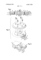
- FIG. 1 is a vertical sectional view taken through the diameter of the pattern wheel of the invention
- FIG. 2 is an exploded perspective view illustrating the manner in which inserted walls are mounted in the pattern wheel of the invention
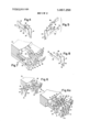
- FIG. 3 is an enlarged fragmentary perspective view showing jacks pivotally mounted on inserted walls in said pattern wheel according to the invention
- FIG. 4 is an enlarged perspective view showing an insertable wall member apart from the pattern wheel and a jack pivotally mounted thereon;
- FIG. 5 is an enlarged perspective view showing a modified insertable wall member and its associated jack
- FIG. 6 is an enlarged fragmentary perspective view showing jacks pivotally mounted on a wire hoop in the pattern wheel of the invention
- FIG. 7 is an enlarged fragmentary perspective view similar to FIG. 3 but illustrating the use of a tucking ring providing a tuck level in the pattern wheel of the invention.
- FIG. 8 is an enlarged perspective view of an insertable wall member adapted to provide a tuck level in a pattern wheel according to the invention.
- FIG. 6A is a view similar to FIG. '6 showing wall members according to FIG. 5.
- the pattern wheel 10 of the invention may be seen as ineluding a ring 12, wall members 14 in evenly spaced slots 16 located in a peripheral marginal portion of the ring, jacks l8 pivotally mounted on the wall members, and a cover 20 securable to the ring 12 by screws 22.
- the slots 16 appear in the drawings in only a portion the ring and only a few selected wall members 14 are shown, it is to be understood that slots are provided all around the ring, that normally each slot 16 is fitted with a wall member 14, and that a jack is provided between each pair of adjacent wall members.
- Each wall member 14 includes a body portion 24, an upper arm 26 with an enlarged end portion 28, and a lower arm 30 having a finger 32 formed thereon.
- the enlarged end portion 28 of each upper arm 26 includes an elongated slot 34.
- the body portions 24 of the wall members extend'in part into the slots 16 and in part project beyond the periphery of the ring 12 to define needle-butt engaging walls 36.
- Arms 30 and fingers 32 thereon extend into recesses 40 and 42 respectively formed in the underside of ring 12 wherein they are secured as by applying a suitable plastic material 44, as for example, a bonding agent such as an epoxy cement; about the parts and permitting it to harden in place to thereby cause the parts to be bonded to the plastic and the plastic to be bonded to the ring.
- a suitable plastic material 44 as for example, a bonding agent such as an epoxy cement
- Jacks 18 are pivotally mounted on the enlarged end portions 28 of the inserted wall members 14 and for this purpose are provided on one side near one end with a protuberance 46 which extends into elongated slot 34 of a wall member.
- the jacks may be pivoted between a needle actuating position (position A) and a non-actuating position (position B). In the needle actuating position the jacks extend toward the outer periphery of the ring and into a position between adjacent walls 36, whereas in the non-actuating position the jacks extend away from the periphery of the ring as shown.
- the wall members 14 When assembling the pattern wheel of FIGS. 1 through 4, the wall members 14 are first inserted and secured in the ring 12, and thereafter the jacks 18 are mounted between adjacent wall members.
- the arms 26 of the wall members are flexed when mounting the jacks to accommodate protuberance 46 as it is moved into registry with slot 34.
- the wall members are perferably formed of thin sheet steel although any other hard durable material which is sufficiently resilient may also be used.
- each wall member may instead be provided as shown in FIG. 5, with a slot 48 having an opening 50 at one end which is smaller in size than the width of the slot and through which the protuberance 46 may be snapped to lodge the protuberance in the slot and so pivotally mount the jack in the wall member.
- Still another way of pivotally mounting the jacks in the pattern wheel involves having the jacks pivoted on a wire hoop 52, and having the ring extend not only through the jacks but also through the wall members 14 such that the ring and therefore the jacks thereon are supported by the wall members.
- the jacks and wall members may all be strung on the wire hoop 52 as for example, in the manner of keys on a split key ring and the wall members then inserted in the slots 16 of the pattern wheel ring. If an open-ended slot is provided in the wall members only the jacks need be strung on the wire hoop 52.
- the wall members may be first inserted in slots 16 and the ring with the jacks properly spaced thereon then snapped into the open-ended slots of the wall members (FIG. 6A).
- the cover is secured to ring 12 after jacks 18 are disposed in needle actuating and non-actuating positions as desired, and in its secured position serves to maintain the jacks in place in the pattern wheel (see FIGS. 1 and 2).
- the cover is fitted over boss 54 on a bearing 56 which is affixed to the ring 12, and is secured to ring 12 with screws 22.
- the pattern wheel bearing 56 has a central bore 58 in which there is provided a sleeve 60 having an axial length slightly in excess of the bore and a stub shaft 62 having a foot 64 at one end.
- the other end 66 of the shaft 62 is threaded to receive a nut 68 which may be tightened to affix the position of the foot 64 in a slot on a knitting machine and maintain the sleeve 60 stationary while the wheel is free to rotate on the sleeve.
- the pattern wheel to FIGS. 1, 2 and 3 is a twoposition wheel, in that when installed for operation on a machine, jacks which are in the needle-actuating position are engageable with needle butts and effective for raising needles to a knit position, whereas jacks which are in a non-actuating position permit needles to pass through the pattern wheel without being raised.
- Such a pattern wheel is, however, convertible to a three-position wheel (FIG. 7) with the addition under the ring 12 of a tucking ring 70 having teeth 72 extending beyond ring 12 and between selected spaces defined by walls 36 to provide surface 74 engageable with needle butts and effective to raise needles to"tuck height when the jacks for such'selected spaces are in the non-actuating position.
- selected wall members 14 may be provided as shown in FIG. 8 with a tab 76 extending at right angles to the body portion 24 and providing a surface 78 for raising needles to a tuck height.
- a pattern wheel comprising a ring with slots in a peripheral marginal portion thereof; an insert in each slot, the inserts extending beyond the slots and defining walls for the pattern wheels, each insert including a jack supporting arm and an additional arm; a bonding agent solidified in place against each of the additional arms and the ring for securing the inserts to the ring; a plurality of pivotally mounted needle-actuating jacks in said wheel supported by and situated between said walls, the jacks being movable between a needleactuating and a non-actuating position; and a cover secured to said ring for holding down jacks in the actuating position and extending over jacks in the nonactuating position.
Landscapes
- Engineering & Computer Science (AREA)
- Textile Engineering (AREA)
- Knitting Machines (AREA)
- Prostheses (AREA)
Priority Applications (7)
| Application Number | Priority Date | Filing Date | Title |
|---|---|---|---|
| US00321630A US3857258A (en) | 1973-01-08 | 1973-01-08 | Pattern wheel with pivoted jacks supported by inserted wall members |
| GB5836873A GB1442146A (en) | 1973-01-08 | 1973-12-17 | Pattern wheel for knitting machines with pivoted jacks supported by inserts |
| JP49004692A JPS49100360A (it) | 1973-01-08 | 1973-12-21 | |
| IT32475/73A IT1002490B (it) | 1973-01-08 | 1973-12-31 | Ruota disegnatrice munita di plati ne imperniate supportate da elemen ti di parete riportati |
| DE2365274A DE2365274A1 (de) | 1973-01-08 | 1973-12-31 | Musterrad fuer rundstrickmaschinen |
| FR7400414A FR2213365B1 (it) | 1973-01-08 | 1974-01-07 | |
| ES422083A ES422083A1 (es) | 1973-01-08 | 1974-01-07 | Un dispositivo de rueda de formacion del dibujo para una maquina tricotosa circular. |
Applications Claiming Priority (1)
| Application Number | Priority Date | Filing Date | Title |
|---|---|---|---|
| US00321630A US3857258A (en) | 1973-01-08 | 1973-01-08 | Pattern wheel with pivoted jacks supported by inserted wall members |
Publications (1)
| Publication Number | Publication Date |
|---|---|
| US3857258A true US3857258A (en) | 1974-12-31 |
Family
ID=23251347
Family Applications (1)
| Application Number | Title | Priority Date | Filing Date |
|---|---|---|---|
| US00321630A Expired - Lifetime US3857258A (en) | 1973-01-08 | 1973-01-08 | Pattern wheel with pivoted jacks supported by inserted wall members |
Country Status (7)
| Country | Link |
|---|---|
| US (1) | US3857258A (it) |
| JP (1) | JPS49100360A (it) |
| DE (1) | DE2365274A1 (it) |
| ES (1) | ES422083A1 (it) |
| FR (1) | FR2213365B1 (it) |
| GB (1) | GB1442146A (it) |
| IT (1) | IT1002490B (it) |
Cited By (2)
| Publication number | Priority date | Publication date | Assignee | Title |
|---|---|---|---|---|
| US5614716A (en) * | 1996-04-26 | 1997-03-25 | Infratemp, Inc. | Alternating current method and apparatus for ambient temperature compensation for modulated energy sensors |
| US9010156B2 (en) | 2010-12-15 | 2015-04-21 | Hugo Kern & Liebers GmbH & Co. KG | Simplified single-knit circular knitting machine |
Families Citing this family (1)
| Publication number | Priority date | Publication date | Assignee | Title |
|---|---|---|---|---|
| CS237609B1 (en) * | 1982-12-21 | 1985-09-17 | Zdenek Gryc | Pattern wheel for knitting frames |
Citations (10)
| Publication number | Priority date | Publication date | Assignee | Title |
|---|---|---|---|---|
| GB176236A (en) * | 1921-02-10 | 1922-03-09 | Arthur Kirkland | Improvements in or relating to patterning devices for circular knitting machines |
| US2008810A (en) * | 1934-04-21 | 1935-07-23 | Samuel Mishcon | Pattern wheel assembly |
| US2055599A (en) * | 1935-12-17 | 1936-09-29 | Samuel Mishcon | Pattern wheel |
| US2140078A (en) * | 1935-10-01 | 1938-12-13 | Brinton Co H | Mutable design wheel for knitting machines |
| DE1128944B (de) * | 1958-12-04 | 1962-05-03 | Fouquet Werk Frauz & Planck | Fuehrungskamm fuer Nadelstoesser, Kulierplatinen u. dgl. an Rundstrick- und Rundwirkmaschinen |
| GB962128A (en) * | 1960-01-26 | 1964-06-24 | Schubert & Salzer Maschinen | Making knitting machine components |
| US3643470A (en) * | 1970-02-06 | 1972-02-22 | Pernick David | Design wheel for knitting machines |
| US3660991A (en) * | 1970-08-10 | 1972-05-09 | Singer Co | Pattern wheel with pivotally mounted jacks |
| US3683645A (en) * | 1970-05-28 | 1972-08-15 | Torrington Co | Pattern wheel with hinged jack |
| US3740972A (en) * | 1970-05-02 | 1973-06-26 | Kroy Knitting Dev Ltd | Patterning wheels for weft knitting machines |
-
1973
- 1973-01-08 US US00321630A patent/US3857258A/en not_active Expired - Lifetime
- 1973-12-17 GB GB5836873A patent/GB1442146A/en not_active Expired
- 1973-12-21 JP JP49004692A patent/JPS49100360A/ja active Pending
- 1973-12-31 DE DE2365274A patent/DE2365274A1/de active Pending
- 1973-12-31 IT IT32475/73A patent/IT1002490B/it active
-
1974
- 1974-01-07 FR FR7400414A patent/FR2213365B1/fr not_active Expired
- 1974-01-07 ES ES422083A patent/ES422083A1/es not_active Expired
Patent Citations (10)
| Publication number | Priority date | Publication date | Assignee | Title |
|---|---|---|---|---|
| GB176236A (en) * | 1921-02-10 | 1922-03-09 | Arthur Kirkland | Improvements in or relating to patterning devices for circular knitting machines |
| US2008810A (en) * | 1934-04-21 | 1935-07-23 | Samuel Mishcon | Pattern wheel assembly |
| US2140078A (en) * | 1935-10-01 | 1938-12-13 | Brinton Co H | Mutable design wheel for knitting machines |
| US2055599A (en) * | 1935-12-17 | 1936-09-29 | Samuel Mishcon | Pattern wheel |
| DE1128944B (de) * | 1958-12-04 | 1962-05-03 | Fouquet Werk Frauz & Planck | Fuehrungskamm fuer Nadelstoesser, Kulierplatinen u. dgl. an Rundstrick- und Rundwirkmaschinen |
| GB962128A (en) * | 1960-01-26 | 1964-06-24 | Schubert & Salzer Maschinen | Making knitting machine components |
| US3643470A (en) * | 1970-02-06 | 1972-02-22 | Pernick David | Design wheel for knitting machines |
| US3740972A (en) * | 1970-05-02 | 1973-06-26 | Kroy Knitting Dev Ltd | Patterning wheels for weft knitting machines |
| US3683645A (en) * | 1970-05-28 | 1972-08-15 | Torrington Co | Pattern wheel with hinged jack |
| US3660991A (en) * | 1970-08-10 | 1972-05-09 | Singer Co | Pattern wheel with pivotally mounted jacks |
Cited By (2)
| Publication number | Priority date | Publication date | Assignee | Title |
|---|---|---|---|---|
| US5614716A (en) * | 1996-04-26 | 1997-03-25 | Infratemp, Inc. | Alternating current method and apparatus for ambient temperature compensation for modulated energy sensors |
| US9010156B2 (en) | 2010-12-15 | 2015-04-21 | Hugo Kern & Liebers GmbH & Co. KG | Simplified single-knit circular knitting machine |
Also Published As
| Publication number | Publication date |
|---|---|
| DE2365274A1 (de) | 1974-07-11 |
| JPS49100360A (it) | 1974-09-21 |
| GB1442146A (en) | 1976-07-07 |
| ES422083A1 (es) | 1976-04-16 |
| FR2213365A1 (it) | 1974-08-02 |
| FR2213365B1 (it) | 1978-11-10 |
| IT1002490B (it) | 1976-05-20 |
Similar Documents
| Publication | Publication Date | Title |
|---|---|---|
| US3857258A (en) | Pattern wheel with pivoted jacks supported by inserted wall members | |
| GB2038376B (en) | Sinker for forming knitted terry fabric on single cylinder circular knitting machines | |
| CS75092A3 (en) | Single-cylinder circular knitting machine with anti-twisting mechanism,particularly for socks and stockings knitting | |
| SG102045A1 (en) | Circular knitting machine | |
| DE69406858D1 (de) | Nadelauswahlvorrichtung für Rundstrickmaschinen für die Herstellung von Socken, Strümpfen und dergleichen | |
| DE69207067D1 (de) | Doppelzylinder-Rundstrickmaschine zur Herstellung von Socken und Strümpfen mit Gestrick-Abzugvorrichtung | |
| KR910004872A (ko) | 환편기 | |
| GB1552501A (en) | Tensioning knitted fabric on a circular knitting machine | |
| US2539137A (en) | Knitting machine guard | |
| DD128603A5 (de) | Fadenliefervorrichtung fuer textilmaschinen,insbesondere fuer strickmaschinen | |
| IT971949B (it) | Apparecchiatura di programmazione elettronica analogica di disegni e o forme su tessuto a maglia in macchine per maglieria rettilinee tubolari o circolari | |
| US3660991A (en) | Pattern wheel with pivotally mounted jacks | |
| JPH11124758A (ja) | 丸編機のシンカーカム交換装置 | |
| DE69015561D1 (de) | Verfahren zum Regeln der Maschengrösse an Strumpfstrickmaschinen. | |
| CH554437A (it) | Apparecchiatura di programmazione elettronica analogica di disegni e/o forme su tessuto a maglia in una macchina per maglieria rettilinea tubolare o circolare. | |
| US3789629A (en) | Pattern device for knitting machines | |
| FR1487558A (fr) | Métier à tricoter circulaire à double cylindre et multichutes pour la fabrication d'un article de bonneterie à maille retournée et motif jacquard en uni | |
| JPS5932627Y2 (ja) | 装飾片編込用の鉤針 | |
| DE69107053D1 (de) | Nadelauswahlvorrichtung für Rundstrickmaschine, insbesondere für Strümpfe. | |
| GB1421094A (en) | Stitch length control in circulat knitting machines | |
| EP0036194A3 (en) | Circular knitting machine of the type having two needle beds for knitting rib patterned tubular fabrics | |
| FR2353665A1 (fr) | Procede de tricotage | |
| IT1073448B (it) | Dispositivo per disegni per macchine per maglieria di pelo specialmente per la produzione di lavori a maglia di pelo a disegno jacquard su macchine per galloni ad uncinetto | |
| GB935148A (en) | Improvements in circular hosiery knitting machines | |
| IT1108745B (it) | Dispositivo per il tiraggio dei tessuti a maglia nelle macchine circolari per maglieria |
Legal Events
| Date | Code | Title | Description |
|---|---|---|---|
| AS | Assignment |
Owner name: MONARCH MANUFACTURING CORP. 74-10 88TH STREET, GLE Free format text: ASSIGNMENT OF ASSIGNORS INTEREST.;ASSIGNOR:VANGUARD SUPREME MACHINE CORPORATION, A NC CORP.;REEL/FRAME:004546/0906 Effective date: 19860312 Owner name: MONARCH MANUFACTURING CORP., NEW YORK Free format text: ASSIGNMENT OF ASSIGNORS INTEREST;ASSIGNOR:VANGUARD SUPREME MACHINE CORPORATION, A NC CORP.;REEL/FRAME:004546/0906 Effective date: 19860312 |