US3852930A - Tridimensional fiber reinforcement of portland cement concrete matrices - Google Patents
Tridimensional fiber reinforcement of portland cement concrete matrices Download PDFInfo
- Publication number
- US3852930A US3852930A US00283438A US28343872A US3852930A US 3852930 A US3852930 A US 3852930A US 00283438 A US00283438 A US 00283438A US 28343872 A US28343872 A US 28343872A US 3852930 A US3852930 A US 3852930A
- Authority
- US
- United States
- Prior art keywords
- fibers
- fiber
- wires
- tridimensional
- enclosures
- Prior art date
- Legal status (The legal status is an assumption and is not a legal conclusion. Google has not performed a legal analysis and makes no representation as to the accuracy of the status listed.)
- Expired - Lifetime
Links
Images


Classifications
-
- E—FIXED CONSTRUCTIONS
- E04—BUILDING
- E04C—STRUCTURAL ELEMENTS; BUILDING MATERIALS
- E04C5/00—Reinforcing elements, e.g. for concrete; Auxiliary elements therefor
- E04C5/01—Reinforcing elements of metal, e.g. with non-structural coatings
- E04C5/02—Reinforcing elements of metal, e.g. with non-structural coatings of low bending resistance
- E04C5/04—Mats
-
- E—FIXED CONSTRUCTIONS
- E04—BUILDING
- E04C—STRUCTURAL ELEMENTS; BUILDING MATERIALS
- E04C5/00—Reinforcing elements, e.g. for concrete; Auxiliary elements therefor
- E04C5/01—Reinforcing elements of metal, e.g. with non-structural coatings
- E04C5/012—Discrete reinforcing elements, e.g. fibres
Definitions
- ABSTRACT Steel fibers or cloth made therefrom having a tridimensional configuration for use as a reinforcement for Portland cement concrete matrices is described.
- enclosures may be connected in series by causing the wires to be sufficiently long'to form two or more enclosures.
- One or more of serially connected enclosures may be used as a reinforcing fiber.
- a continuous fiber is formed by connecting in series a relatively large number of enclosures.
- a group of parallel, continuous fibers may be laterally connected to form a tridimen- 6 Claims, 19 Drawing Figures [52] US. Cl 52/664, 52/600, 52/659, 52/736 [51] Int. Cl. E04c 5/01 [58] Field of Search 52/600, 664, 630, 719, 52/736, 660, 414, 735, 676, 454, 740, 733 734; 245/2, 5
- FIG.2 is a diagrammatic representation of FIG. 1
- This invention relates to a fiber configuration for use as a reinforcement for a concrete matrix and in particular to steel fibers having a tridimensional structure for use as reinforcement in a concrete or cement matrix.
- Steel fibers whichare conventionally used have diameters ranging from 4 to 30 mils, a length between onequarter and 2 inches and a tensile strength between 100,000 and 400,000 psi. Obtaining a uniform dispersion of the fibers and preventing their segregation appears to be the most difficult problem in preparing a composite of these fibers and concrete.
- segregation is related to two reinforcement parameters: the aspect ratio of the fibers and their fraction volume in the mix. Increasing the aspect ratio or increasing the fraction volume of the fibers increases tendency to segregation and destroys the uniformity of the composite.
- steel fibers in concrete are mainly limited by the cost/efficiency ratio.
- the price per pound of steel fibers will likely remain at least three or four times the cost of conventional reinforcing steel. It seems, therefore, that steel fiber reinforcement in its previous form is not able to compete in applications where conventional reinforcement is satisfactory.
- Coating the fibers and improving mechanical bonding by spiralling the fibers or deforming the fibers assist in improving the performance of the composite but are unable to solve the problem completely. Some improvement is expected by using closed form fibers such as rings or rectangles; however, segregation remains a problem.
- the tridimensional fibers of this invention can be used as discontinuous reinforcement, as straight fibers are, where the number of basic elements which are serially connected is small and forms a fiber which is not long relative to its lateral dimensions.
- Such fibers can be mixed with the concrete matrix prior to pouring, incurring less segregation problems than straight fibers.
- the concrete matrix may be poured over the fibers which are previously placed in a form, and pile up due to their tridimensional shape to occupy part or the entire volume of the form.
- Discontinuous tridimensional fibers are more efficient than straight wires with respect to improvement in tensile strength, toughness, cracking, bonding and ductility.
- the tridimensional fibers may also be constructed to form a continuous fiber by serially connecting a group of basic elements whose total length extends over a substantial portion of the length of the structure of which it is to form the reinforcement. These continuous fibers may be formed into a cloth by spaced wires laterally joining parallel spaced continuous fibers. Continuous or cloth tridimensional fibers allow the use of high strength steel while still achieving ductility through crushing of the concrete matrix in which they are embedded when the applied load is high enough. There is also an increase in the efficiency of energy absorption, impact resistance, cracking and ductility. Where cloth is used, there is no need for spacers to laterally and/or vertically separate the continuous fibers.
- Tridimensional fibers of the continuous or discontinuous type offer savings in time and labor over conventional reinforceing rods which must be secured in place.
- Tridimensional fibers also have the advantage over conventional reinforcing steel that with a relatively simple, inexpensive machine they can be fabricated onsite from spools of wire.
- FIG. 1 shows one embodiment of the tridimensional fiber element, identified as the type 1 element
- FIG. 2 shows an alternate embodiment of the tridimensional element, identified as the type 2 element
- FIG. 3(a) shows a first mode of reinforcing concrete where the tridimensional elements are uniformly disposed
- FIG. 3(b) shows a second mode of reinforcing concrete where tridimensional elements are concentrated in the tensile stress area of the concrete
- FIG. 3(0) shows a third mode or reinforcing concrete where the tridimensional elements are in a single layer just covered by the concrete
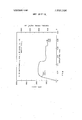
- FIG. 4(a) is a graph of stress versus strain for a low yield strength ductile steel fiber
- FIG. 4(b) is a graph of stress versus strain for a high yield strength brittle steel fiber
- FIG. 5 is a graph of load versus elongation for conventional fiber-reinforced concrete under tensile load-
- FIG. 6 shows graphs of load versus deflection for conventional fiber-reinforced concrete under flexural loading;
- FIG. 7 shows graphs of load versus deflection for a type 1 tridimensional fiber element reinforced concrete using the first modeof reinforcement with ductile steel
- FIG. 10 are graphs of load versus deflection of a type 2 tridimensional fiber element-reinforced concrete I using the first mode of reinforcement with ductile steel;
- FIG. 11 shows graphs of load versus deflection for a type 2 continuous tridimensional fiber elementreinforced concrete using the second mode of reinforcement with ductile steel
- FIG. 12 shows graphs of load versus deflection for a type 2 continuous tridimensional fiber elementreinforced concrete using the second mode of reinforcement with brittle steel
- FIG. 13 shows a graph of load versus deflection for a type 2 continuous tridimensional fiber elementreinforced concrete using the second mode of reinforcement with brittle steel and incompletely cured concrete
- FIG. 14 shows continuous fibers attached to each other to form a cloth.
- the tridimensional fiber of the skeletal type has the property that the bond strength of the steel in concrete is increased by a fiber of this form by adding a mechanical component to bond.
- Tridimensional fibers may have a great variety of shapes, for instance, that of a tetrapode or spherical skeleton.
- FIGS. 1 and 2 Two preferred embodiments are shown in FIGS. 1 and 2, where the skeletal arrangement of the wires approximate an ellipsoid.
- FIG. 1 shows four wires 10 equally spaced from each other to form the skeletal outline ll of an ellipsoid. The wires are twisted together at the ends l2, 13 of the ellipsoid; and, in the embodiments shown in FIGS. 1 and 2, the wires are continued to form another element 14 identical to that of element 11. Together, elements 11 and 14 form a fiber designated as type 1 fiber in the test results to be subsequently presented.
- FIG. 2 An alternate embodiment of the tridimensional element is shown in FIG. 2, where only three equally spaced wires 20 form the ellipsoidal skeleton, and the fourth wire 21 joins the others where they are twisted together at the ends 12, 13 of the ellipsoid to form an element 22. Elements 22 and 23 are joined to each other to form a type 2 fiber as designated in the test results to be subsequently presented.
- tridimensional fibers may be fabricated of as little as one of the elements 11 or 22 or may be formed of a large number of serially connected elements.
- test results are disclosed for fibers having two elements which have been designated as discontinuous fibers and for fibers having eight elements, which have been designated as continuous fibers.
- a second advantage is that the fibers may be thrown into a mold before pouring in the concrete matrix because the elements pile up to occupy a volume into which the concrete matrix may penetrate.
- the concrete matrix may have aggregate limited in size to the openings of the element, and penetration into the element may be assisted by conventional vibration techniques. Therefore, there is considerable freedom in designing the mix, and the risk of segregation is eliminated.
- a third advantage of the three dimensional fiber elements relates to their volume-enclosing shape which, upon high enough elongation stresses, tends to cause crushing of the enclosed matrix, which produces a ductile type of failure even though the fibers themselves may be brittle steel of high yield strength. Also, three dimensional fibers act as crack arrestors and toughening agents because of the enormous lateral bonded area they offer the surrounding matrix.
- joining may be obtained by twisting as in preferred embodiments, or by clamping, welding, gluing, etc. Twisting the wires is expected to provide a lower apparent modulus and higher elongations (by untwisting) but should be done uniformly as otherwise the strength of the twisted strand formed would be drastically reduced.
- Mode 2 shown in FIG. 3(b) is in some way similar to conventional reinforcement: throwing in a certain amount of fibers which, when ultimately embedded in the matrix. will form the tensile load carrying element. This procedure is very easy, for example, in simply supported beams where reinforcement is needed in the bottom region.
- the tridimensional fiber has the advantage that the element is well anchored to the concrete matrix by the skeletal shape of the fibers. Transfer of load from fiber to fiber is obtained by shearing of the matrix in between overlapping links. On the other hand, if used as a continuous reinforcement, it has the advantage of increasing the bond strength and efficiency of reinforcement against cracking.
- failure can occur through one or a combination of the following situations: (a) the fibers, if discontinuous, pull out; but, due to their bonding properties, this occurs at a much higher load than with straight fibers, everything else being equal; (b) the wires forming the fiber reach their yielding point and lead to the failure of the member; (c) the matrix volume, sustaining the load transfer between overlapping discontinuous fibers, reaches its failure point; (d) the matrix inside the volume enclosed by fiber reaches its failure point under complex multiaxial stresses.
- the testing program consists of two major parts: the first one deals with specimens reinforced with straight steel fibers; and, for comparison, the second one uses the two types of tridimensional fibers of FIGS. 1 and 2.
- Tests of Tridimensional Steel Fibers The second part of the test program consists of several series of single tests under flexural loading, except for series C which was tested under tension. Both types of tridimensional fibers described in FIGS. 1 and, 2 were used under the three reinforcing modes indicated in FIG. 3: namely, mode 1 and 2 for flexure, mode 3 for tension.
- series A, B and C tridimensional discontinuous fibers, the type 1 element of FIG. 1 and stainless steel low yield ductile wire were used under the three reinforcing modes already mentioned.
- Series A, FIG. 7, corresponding to the first reinforcing mode of FIG. 3(a) was made up of three specimens having different volume fractions of fibers (obtained by using different wire diameters). Fibers were thrown into the mold where they piled up filling it completely. Then, the mortar matrix was poured, and a slight vibration applied to insure good penetration.
- FIG. 9 investigated the third reinforcing mode of FIG. 3(0) by working with tensile plates. One layer of fibers was thrown into the mold, and then just enough mortar was poured to cover it completely. Thickness of the specimen was recorded before testing.
- FIGS. ll, 12 and G, FIG. 13 were performed in order to investigate the behavior of specimens reinforced with tridimensional continuous fibers of type 2 elements. Each specimen was reinforced with 20 strands thrown in the lower half of the beam. Series E was divided into two parts using the two types of steel mentioned: low yield, high ductility, FIG. 11, and high yield, low ductility, FIG. 12. Strength and ductility of the reinforced members had to be compared. As the ductility of specimens E3 and E4 (reinforced with high strength strands) was quite low, it was necessary to investigate the mutual interaction between the load carried by the fiber and the matrix.
- specimen G was prepared with the tensile reinforcement as specimen E4 and with the same matrix composition, but was tested 24 hours after pouring, when the strength of the matrix would have been 20 to 30 percent of the expected strength at 7 days.
- the failure of specimen G was much more ductile than E4 proving that it is possible to obtain ductile failure by a combined interaction between fibers and matrix.
- FIG. 9 shows an improved ductile type of failure for tridimensional fibers as well as high cracking and disruption of the matrix close to the major opening crack.
- FIGS. 6 and 7 Comparing FIGS. 6 and 7, we can easily see that the energy absorbed at failure, taken as area under the load deflection curve, in series A (tridimensional fibers) FIG. 7, as an example, is one order of magnitude higher than a similarly reinforced specimen of straight fibers, FIG. 6. This trend is general, as shown in the other series of experiments, FIGS. 8-10. It should be noted, however, that the ductile property of the steel has certainly also considerable influence on the ductile failure observed in these tests.
- specimen G of FIG. 13 having the same tensile reinforcement as E4, was meant to investigate the possibility of a combined action between tridimensional fiber and matrix which will result in a ductile type of failure. This action was obtained by testing specimen G just 24 hours after pouring, at which time the compressive strength of the matrix was relatively low. Under applied tensile stresses the skeletal part of the tridimensional fiber tends to stretch, crushing the inner, weak concrete matrix and so allowing for more extension and ductility. The improvement in ductility can be observed by comparing the load deflection curves of specimens E4 of FIG. 12 and that of FIG. 13.
- a reinforcing fiber for a concrete matrix comprising a plurality of three or more steel wires, said wires forming a skeletal outline of a volumetric enclosure, said wires being substantially equally spaced from each other on said enclosure, said wires being joined together at opposite ends of the enclosure, an additional steel wire through the center of said volumetric enclosure, joining the other skeletal wires at the ends of the enclosures.
- the reinforcing fiber of claim 1 comprising, in addition,
- each wire of said plurality being connected to a continuous fiber to form a grid-like fiber cloth.
- said joined wires are wires that are twisted about each other.
Landscapes
- Engineering & Computer Science (AREA)
- Architecture (AREA)
- Civil Engineering (AREA)
- Structural Engineering (AREA)
- Curing Cements, Concrete, And Artificial Stone (AREA)
Abstract
Steel fibers or cloth made therefrom having a tridimensional configuration for use as a reinforcement for Portland cement concrete matrices is described. At least three wires, approximately equally laterally spaced from each other, skeletally enclose a volume in the approximate shape of a sphere or ellipsoid; the wires are joined to one another where they meet along the axis of the volume enclosed to form the basic tridimensional element termed an ''''enclosure''''. These enclosures may be connected in series by causing the wires to be sufficiently long to form two or more enclosures. One or more of serially connected enclosures may be used as a reinforcing fiber. A continuous fiber is formed by connecting in series a relatively large number of enclosures. A group of parallel, continuous fibers may be laterally connected to form a tridimensional cloth.
Description
United States Patent [191 Naaman Antoine E. Naaman, Cambridge, Mass.
[73] Assignee: Massachusetts Institute of Technology, Cambridge, Mass.
[22] Filed: Aug. 24, 1972 [21] Appl. No.:283,438
[75] Inventor:
[451 Dec. 10,1974
Primary Examiner--Henry C. Sutherland Assistant Examiner-Carl D. Friedman Attorney, Agent, or FirmArthur A. Smith, Jr.; Martin M. Santa; Robert Shaw [5 7] ABSTRACT Steel fibers or cloth made therefrom having a tridimensional configuration for use as a reinforcement for Portland cement concrete matrices is described. At least three wires, approximately equally laterally spaced from each other, skeletally enclose a volume in the approximate shape of a sphere or ellipsoid; the wires are joined to one another where they meet along the axis of the volume enclosed to form the basic tridimensional element termed an enclosure. These enclosures may be connected in series by causing the wires to be sufficiently long'to form two or more enclosures. One or more of serially connected enclosures may be used as a reinforcing fiber. A continuous fiber is formed by connecting in series a relatively large number of enclosures. A group of parallel, continuous fibers may be laterally connected to form a tridimen- 6 Claims, 19 Drawing Figures [52] US. Cl 52/664, 52/600, 52/659, 52/736 [51] Int. Cl. E04c 5/01 [58] Field of Search 52/600, 664, 630, 719, 52/736, 660, 414, 735, 676, 454, 740, 733 734; 245/2, 5
[56] References Cited UNITED STATES PATENTS 906,479 12/1908 Whitacre 52/733 1,046,913 12/1912 Weakley 52/736 X Sional cloth 1,124,170 l/1915 Rechnitz 52/676 2,754,674 7/1956 Mulsbury et a1 52/734 X PATENTED DEC 10 I974 sum r01 or 12 FIG.|
FIG-.2
FIG. 3(A) FIG. 3(8) FIG. 3(C) PAIENIEU HEB I0 I974 sum '02 or i2 Z FAILURE m" (I) i Low YIELD 50 DUCTILE STEEL (STAINLESS) 0 I 1 l l l l l o 0 2 1 0.4 0.6 0.8 L0 L2 I I r-- v ELONGATION PER INCHI FIG. 4(A) FAILURE g HIGH YIELD BRITTLE STEEL w 50 b=o.o2o I =0.oI5
o l l l ELONGATION. PER INCH FIG. 4(8) TRIDIMENSIONAL FIBER REINFORCEMENT OF PORTLAND CEMENT CONCRETE MATRICES This invention herein described was made in the course of a contract, No. DAHC l5-67-C-0222, with the Advanced Research Projects Agency.
This invention relates to a fiber configuration for use as a reinforcement for a concrete matrix and in particular to steel fibers having a tridimensional structure for use as reinforcement in a concrete or cement matrix.
'due to discontinuity. Its use in structural elements,
when design justifies economical considerations, is mainly in combination with conventional reinforcement.
Steel fibers whichare conventionally used have diameters ranging from 4 to 30 mils, a length between onequarter and 2 inches and a tensile strength between 100,000 and 400,000 psi. Obtaining a uniform dispersion of the fibers and preventing their segregation appears to be the most difficult problem in preparing a composite of these fibers and concrete. Experience with steel fibers has shown that segregation is related to two reinforcement parameters: the aspect ratio of the fibers and their fraction volume in the mix. Increasing the aspect ratio or increasing the fraction volume of the fibers increases tendency to segregation and destroys the uniformity of the composite.
The use of steel fibers in concrete is mainly limited by the cost/efficiency ratio. The price per pound of steel fibers will likely remain at least three or four times the cost of conventional reinforcing steel. It seems, therefore, that steel fiber reinforcement in its previous form is not able to compete in applications where conventional reinforcement is satisfactory.
These prior-art fibers have as their primary function that of being an impact or shock energy absorber. However, a second but not less important function for fibers would be as a tensile bearing component identical to conventional reinforcement in reinforced concrete. Experimental data shows that a common description of the failure mechanism of a composite is that, after cracking of the matrix, specimens failed by pulling out of the fibers bridging the fracture surfaces. There exists a lack of bonding leading to a low failure strength. The strength of the fiber is inefficiently used. Attempts to improve this bonding by increasing the length of the fibers results in increasing the aspect ratio which leads to segregation and not the desired composite material. Coating the fibers and improving mechanical bonding by spiralling the fibers or deforming the fibers assist in improving the performance of the composite but are unable to solve the problem completely. Some improvement is expected by using closed form fibers such as rings or rectangles; however, segregation remains a problem.
The tridimensional fibers of this invention can be used as discontinuous reinforcement, as straight fibers are, where the number of basic elements which are serially connected is small and forms a fiber which is not long relative to its lateral dimensions. Such fibers can be mixed with the concrete matrix prior to pouring, incurring less segregation problems than straight fibers. If mixing the discontinuous fibers in the matrix is not desired, the concrete matrix may be poured over the fibers which are previously placed in a form, and pile up due to their tridimensional shape to occupy part or the entire volume of the form. Discontinuous tridimensional fibers are more efficient than straight wires with respect to improvement in tensile strength, toughness, cracking, bonding and ductility.
The tridimensional fibers may also be constructed to form a continuous fiber by serially connecting a group of basic elements whose total length extends over a substantial portion of the length of the structure of which it is to form the reinforcement. These continuous fibers may be formed into a cloth by spaced wires laterally joining parallel spaced continuous fibers. Continuous or cloth tridimensional fibers allow the use of high strength steel while still achieving ductility through crushing of the concrete matrix in which they are embedded when the applied load is high enough. There is also an increase in the efficiency of energy absorption, impact resistance, cracking and ductility. Where cloth is used, there is no need for spacers to laterally and/or vertically separate the continuous fibers.
Tridimensional fibers of the continuous or discontinuous type offer savings in time and labor over conventional reinforceing rods which must be secured in place.
Tridimensional fibers also have the advantage over conventional reinforcing steel that with a relatively simple, inexpensive machine they can be fabricated onsite from spools of wire.
It is therefore an object of this invention to produce a fiber configuration which incurs less segregation problems than prior art fibers if mixed with a concrete matrix prior to pouring or which may, if desired, be
placed in a mold prior to pouring the concrete over the fibers.
It is a further object of the invention to produce a fiber which gives the matrix in which it is placed greater tensile strength, bonding, toughening and ductility than obtainable with prior art fibers.
It is a still further object of the invention to produce a fiber which is self-spacing, susceptible to on-site fabrication and capable of being formed as a cloth.
Other objects and features of the present invention will be apparent from the following description of tridimensional fiber elements read in conjunction with figures in which FIG. 1 shows one embodiment of the tridimensional fiber element, identified as the type 1 element;
FIG. 2 shows an alternate embodiment of the tridimensional element, identified as the type 2 element;
FIG. 3(a) shows a first mode of reinforcing concrete where the tridimensional elements are uniformly disposed;
FIG. 3(b) shows a second mode of reinforcing concrete where tridimensional elements are concentrated in the tensile stress area of the concrete;
FIG. 3(0) shows a third mode or reinforcing concrete where the tridimensional elements are in a single layer just covered by the concrete;
FIG. 4(a) is a graph of stress versus strain for a low yield strength ductile steel fiber;
FIG. 4(b) is a graph of stress versus strain for a high yield strength brittle steel fiber;
FIG. 5 is a graph of load versus elongation for conventional fiber-reinforced concrete under tensile load- FIG. 6 shows graphs of load versus deflection for conventional fiber-reinforced concrete under flexural loading;
FIG. 7 shows graphs of load versus deflection for a type 1 tridimensional fiber element reinforced concrete using the first modeof reinforcement with ductile steel;
gation for a type 1 tridimensional fiber element-- reinforced concrete using the third mode of reinforcement with different wire diameters and volume fraction of ductile steel;
FIG. 10 are graphs of load versus deflection of a type 2 tridimensional fiber element-reinforced concrete I using the first mode of reinforcement with ductile steel;
FIG. 11 shows graphs of load versus deflection for a type 2 continuous tridimensional fiber elementreinforced concrete using the second mode of reinforcement with ductile steel;
FIG. 12 shows graphs of load versus deflection for a type 2 continuous tridimensional fiber elementreinforced concrete using the second mode of reinforcement with brittle steel;
FIG. 13 shows a graph of load versus deflection for a type 2 continuous tridimensional fiber elementreinforced concrete using the second mode of reinforcement with brittle steel and incompletely cured concrete; and
FIG. 14 shows continuous fibers attached to each other to form a cloth.
The tridimensional fiber of the skeletal type has the property that the bond strength of the steel in concrete is increased by a fiber of this form by adding a mechanical component to bond. Tridimensional fibers may have a great variety of shapes, for instance, that of a tetrapode or spherical skeleton. Two preferred embodiments are shown in FIGS. 1 and 2, where the skeletal arrangement of the wires approximate an ellipsoid. FIG. 1 shows four wires 10 equally spaced from each other to form the skeletal outline ll of an ellipsoid. The wires are twisted together at the ends l2, 13 of the ellipsoid; and, in the embodiments shown in FIGS. 1 and 2, the wires are continued to form another element 14 identical to that of element 11. Together, elements 11 and 14 form a fiber designated as type 1 fiber in the test results to be subsequently presented.
An alternate embodiment of the tridimensional element is shown in FIG. 2, where only three equally spaced wires 20 form the ellipsoidal skeleton, and the fourth wire 21 joins the others where they are twisted together at the ends 12, 13 of the ellipsoid to form an element 22. Elements 22 and 23 are joined to each other to form a type 2 fiber as designated in the test results to be subsequently presented.
It is apparent that tridimensional fibers may be fabricated of as little as one of the elements 11 or 22 or may be formed of a large number of serially connected elements. In this application, test results are disclosed for fibers having two elements which have been designated as discontinuous fibers and for fibers having eight elements, which have been designated as continuous fibers.
The type 1 and 2 elements used to perform the tests disclosed in this application had typical respective dimensions a z 3.2 to 3.5 inches and 3 inches, b l inch and 0.75 inches and c z 0.5 inches, where a, b and c are the dimensions illustrated on FIGS. 1 and 2. To ascertain the effect of wire diameter on the strength of the concrete matrix in which the elements were embedded, wire diameters ranging from 0.012 to 0.032 inches were used. The wire size for each element tested is given on the figures. Larger wire sizes than those used appear desirable but were not tested because the machine used in fabricating the elements was incapable of handling larger wire sizes.
Besides the higher bonding properties of three dimensional fiber elements in comparison to the ordinary steel fiber, a second advantage is that the fibers may be thrown into a mold before pouring in the concrete matrix because the elements pile up to occupy a volume into which the concrete matrix may penetrate. The concrete matrix may have aggregate limited in size to the openings of the element, and penetration into the element may be assisted by conventional vibration techniques. Therefore, there is considerable freedom in designing the mix, and the risk of segregation is eliminated.
A third advantage of the three dimensional fiber elements relates to their volume-enclosing shape which, upon high enough elongation stresses, tends to cause crushing of the enclosed matrix, which produces a ductile type of failure even though the fibers themselves may be brittle steel of high yield strength. Also, three dimensional fibers act as crack arrestors and toughening agents because of the enormous lateral bonded area they offer the surrounding matrix.
Variations in the shape of the links and the methods of joining the wires along the fiber axis between links are left to the choice of the designer. For example, joining may be obtained by twisting as in preferred embodiments, or by clamping, welding, gluing, etc. Twisting the wires is expected to provide a lower apparent modulus and higher elongations (by untwisting) but should be done uniformly as otherwise the strength of the twisted strand formed would be drastically reduced.
Three methods of using the fiber elements of FIGS. 1 and 2 have been investigated and are presented shcematically in FIG. 3. Mode 2 shown in FIG. 3(b) is in some way similar to conventional reinforcement: throwing in a certain amount of fibers which, when ultimately embedded in the matrix. will form the tensile load carrying element. This procedure is very easy, for example, in simply supported beams where reinforcement is needed in the bottom region.
The tridimensional fiber has the advantage that the element is well anchored to the concrete matrix by the skeletal shape of the fibers. Transfer of load from fiber to fiber is obtained by shearing of the matrix in between overlapping links. On the other hand, if used as a continuous reinforcement, it has the advantage of increasing the bond strength and efficiency of reinforcement against cracking. I
If the appliedload is high enough, failure can occur through one or a combination of the following situations: (a) the fibers, if discontinuous, pull out; but, due to their bonding properties, this occurs at a much higher load than with straight fibers, everything else being equal; (b) the wires forming the fiber reach their yielding point and lead to the failure of the member; (c) the matrix volume, sustaining the load transfer between overlapping discontinuous fibers, reaches its failure point; (d) the matrix inside the volume enclosed by fiber reaches its failure point under complex multiaxial stresses.
It is a priori easy to imagine that, for a combination of specific variables, ductile failure of a three dimensional fiber-reinforced member may be expected at a relatively high enough stress. For example, for failure as in (b), it is sufficient that the wire be ductile. In the last two cases, (c) and (d), it seems necessary that the load carried by the fiber is higher than some particular value. beyond which the matrix will be crushed, allowing further elongation of the fiber and therefore ductility for the member. In other words, a combined action is expected for ductile behavior.
The testing program consists of two major parts: the first one deals with specimens reinforced with straight steel fibers; and, for comparison, the second one uses the two types of tridimensional fibers of FIGS. 1 and 2.
Matrix Composition Essentially the same mortar matrix was used throughout the test program. High early Portland cement type III and fine graded Ottawa silica sand(ASTM C-l09) were mixed with water in the following proportions: water to cement ratio =O.6; sand to cement ratio 2.5.
For the tests involving tridimensional fibers, the fibers were thrown into the empty mold and then the mortar matrix was poured. A slight vibration was applied to allow good penetration. However, using the seventh day, except for series G which was tested before curing, i.e., tested 24 hours after pouring. Prior Art Straight Steel Fibers For purposes of comparison with the tridimensional fiber elements of the invention, tests were made of straight steel fiber reinforced concrete with parameters within average values recommended by most previous investigators in order to avoid experimental obstacles, mainly segregation of the fibers, etc. Typical load elongation curves for tensile and flexural specimens reinforced with straight steel fibers are shownin FIGS. 5 and 6, respectively. The fibers used were high yield, brittle steel, as in FIG. 4(b), 0.75 inches in length and 0.016 inches in diameter, uniformly mixed in the concrete matrix. The fractional volume of fibers is shown on the curves of the figures. It is seen that higher fractional volumes of fiber produces higher peak load capacity and greater energy absorption which is measured by the area under the load-elongation or loaddefiection curves.
Tests of Tridimensional Steel Fibers The second part of the test program consists of several series of single tests under flexural loading, except for series C which was tested under tension. Both types of tridimensional fibers described in FIGS. 1 and, 2 were used under the three reinforcing modes indicated in FIG. 3: namely, mode 1 and 2 for flexure, mode 3 for tension.
Two types of steel wires were used for the tridimensional fibers tested in this study: stainless steel with low yield stress and very high ductility, carbon steel with high yield and low ductility. Typical stress elongation curves are illustrated in FIG. 4.
For series A, B and C, tridimensional discontinuous fibers, the type 1 element of FIG. 1 and stainless steel low yield ductile wire were used under the three reinforcing modes already mentioned. Series A, FIG. 7, corresponding to the first reinforcing mode of FIG. 3(a) was made up of three specimens having different volume fractions of fibers (obtained by using different wire diameters). Fibers were thrown into the mold where they piled up filling it completely. Then, the mortar matrix was poured, and a slight vibration applied to insure good penetration.
Series B, FIG. 8, corresponding to the second reinforcing mode of FIG. 3(b), consisted of only one specimen in which the fibers were thrown into the lower half part of the beam in order to form the tensile load carrying element (similarly to conventionally reinforced structures).
Series C, FIG. 9, investigated the third reinforcing mode of FIG. 3(0) by working with tensile plates. One layer of fibers was thrown into the mold, and then just enough mortar was poured to cover it completely. Thickness of the specimen was recorded before testing. The three sepcimens C1, C2 and C3 of FIGS. 9(a), (b) and (c), respectively, had the following dimensions: 2 X 0.625 X 12, 2 X 0.825 X I2 and 2 X 0.75 X 12 inches.
The series D, FIG. 10, experiments were mainly intended to repeat series A using the FIG. 2 type of tridimensional discontinuous fibers. However, due to difficulties in producing the fibers, smaller wire diameters were chosen.
Series E, FIGS. ll, 12 and G, FIG. 13, were performed in order to investigate the behavior of specimens reinforced with tridimensional continuous fibers of type 2 elements. Each specimen was reinforced with 20 strands thrown in the lower half of the beam. Series E was divided into two parts using the two types of steel mentioned: low yield, high ductility, FIG. 11, and high yield, low ductility, FIG. 12. Strength and ductility of the reinforced members had to be compared. As the ductility of specimens E3 and E4 (reinforced with high strength strands) was quite low, it was necessary to investigate the mutual interaction between the load carried by the fiber and the matrix. It would have been necessary to use higher diameter wires to investigate the possibility of a ductile type of failure due to a crushing of the matrix within the volume enclosed by the element. As it was difficult, with the available equipment, to produce tridimensional strands of higher diameters, the strength of the matrix was reduced instead. Therefore, specimen G was prepared with the tensile reinforcement as specimen E4 and with the same matrix composition, but was tested 24 hours after pouring, when the strength of the matrix would have been 20 to 30 percent of the expected strength at 7 days. The failure of specimen G was much more ductile than E4 proving that it is possible to obtain ductile failure by a combined interaction between fibers and matrix. Testing Procedure All testing was performed using an INSTRON Universal testing machine which applied load at a rate of 0.05 inch/minute for all the flexural and tensile tests. Load-deformation curves were automatically plotted on a chart recorder. These deformations, representing deflections or elongations, are the sum of the specimen deformation and that of the testing system. Their value is, therefore, comparative but not absolute. The load deformation curves are shown in FIGS. 543. Discontinuous Reinforcement Considering firt series A, B, C and D which involved the use of tridimensional discontinuous fibers of either type I or 2 made with ductile steel, FIGS. 7l0, it is observed that higher ultimate stresses, more drastic crack propagation and more significant ductile failure and so energy absorption was obtained than with straight steel fibers as shown in FIGS. and 6. Even at relatively low percentages of reinforcement, the post-cracking load was higher than the first crack load and yield type behavior occurred before failure. The drop in the loaddeformation curve after maximum load was in general very smooth, creating a kind of plateau, typical of good ductile behavior and energy absorption. This occurred even for specimen B, which was only partially reinforced as in conventional beams. The number of cracks in the middle of the flexural beams was significantly higher, at least 5, compared to one crack that developed in a similar specimen reinforced with straight fibers. This results from the higher efficiency of tridimensional fibers due to their length, bonding properties, higher directionality and geometrical shape.
Comparing the load curves of FIGS. 7-10 with respect to load and ductility, we can observe betterresults in series A, reinforced with type 1 fibers, than in series D, reinforced with type 2 fibers. A priori it had been expected, at least with respect to strength, that the type 2 fibers would be better. However, it was observed that, in series D, the main crack occurred and opened along a section where a big number of fiber ends were visible. The presence ofa higher concentration of ends in a cross section is due to the end plate effect of the molds. In order to reduce this effect, a V- shaped piece of wire mesh was placed at each end of the mold in series A, B and C. This procedure was not followed for series D. However, this sort of effect would be automatically eliminated in a member of larger size, or greatly reduced by using discontinuous fibers of different sizes. Results of tensile tests in series C are somehow difficult to compare with those obtained with straight fibers, due mainly to differences in the geometry of the specimens and the testing apparatus used. Qualitatively, however, FIG. 9 shows an improved ductile type of failure for tridimensional fibers as well as high cracking and disruption of the matrix close to the major opening crack.
Comparing FIGS. 6 and 7, we can easily see that the energy absorbed at failure, taken as area under the load deflection curve, in series A (tridimensional fibers) FIG. 7, as an example, is one order of magnitude higher than a similarly reinforced specimen of straight fibers, FIG. 6. This trend is general, as shown in the other series of experiments, FIGS. 8-10. It should be noted, however, that the ductile property of the steel has certainly also considerable influence on the ductile failure observed in these tests.
No shear failure was observed in specimens uniformly reinforced (Mode 1, series A-D) indicating that tridimensional fibers, similar to straight fibers, do enhance the shear resistance of the concrete matrix. Continuous Reinforcement At failure the tridimensional strand reinforced beams of series E of FIG. ll, 12 and G of FIG. 13 showed extensive crack propagation in the region of the constant moment. In series E, specimens E3 and E4, FIG. 12, reinforced with high yield, brittle steel, showed much lower ductility at failure than specimens El and E2, FIG. 11, reinforced with low yield, ductile steel, while a similar order of strength was observed for the same fraction volume of reinforcement, El versus E4. These results indicate that the steel properties are of major importance; and that, in this particular series of tests, ductility of the steel leads to a ductile type of failure. In general, failure occurred progressively with the fracture of the reinforcing fibers by one or more of their wire components.
From the results in series E, it is deduced that, for the particular characteristics of the components used, the ductility of the steel determined whether there was ductile behavior of the member before failure. As it was mentioned earlier, specimen G of FIG. 13, having the same tensile reinforcement as E4, was meant to investigate the possibility of a combined action between tridimensional fiber and matrix which will result in a ductile type of failure. This action was obtained by testing specimen G just 24 hours after pouring, at which time the compressive strength of the matrix was relatively low. Under applied tensile stresses the skeletal part of the tridimensional fiber tends to stretch, crushing the inner, weak concrete matrix and so allowing for more extension and ductility. The improvement in ductility can be observed by comparing the load deflection curves of specimens E4 of FIG. 12 and that of FIG. 13.
In summary of the test results, it can be said that, on the basis of strength, tridimensional continuous reinforcement gave, in general, lower values than theoretically predicted using A.C.I. ultimate moment formula for reinforced concrete; while, on the basis of cracking propagation, ductility and energy absorption, drastic improvements over conventional reinforcement have been achieved.
What is claimed is: l. A reinforcing fiber for a concrete matrix comprising a plurality of three or more steel wires, said wires forming a skeletal outline of a volumetric enclosure, said wires being substantially equally spaced from each other on said enclosure, said wires being joined together at opposite ends of the enclosure, an additional steel wire through the center of said volumetric enclosure, joining the other skeletal wires at the ends of the enclosures. 2. The reinforcing fiber of claim 1 comprising, in addition,
a plurality of said fibers, said fibers being serially connected at the ends where said wires are joined together to form a continuous fiber having a plurality of enclosures.
a plurality of wires substantially parallel and transverse to the direction of said continuous fibers, each wire of said plurality being connected to a continuous fiber to form a grid-like fiber cloth. 6. The fiber of claim 2 wherein said joined wires are wires that are twisted about each other.
l l l =l
Claims (6)
1. A reinforcing fiber for a concrete matrix comprising a plurality of three or more steel wires, said wires forming a skeletal outline of a volumetric enclosure, said wires being substantially equally spaced from each other on said enclosure, said wires being joined together at opposite ends of the enclosure, an additional steel wire through the center of said volumetric enclosure, joining the other skeletal wires at the ends of the enclosures.
2. The reinforcing fiber of claim 1 comprising, in addition, a plurality of said fibers, said fibers being serially connected at the ends where said wires are joined together to form a continuous fiber having a plurality of enclosures.
3. The reinforcing fiber of claim 2 wherein said wires forming a fiber enclosure are continued without being broken and formed into serially connected fiber enclosures called a continuous fiber.
4. The reinforcing fiber of claim 3 wherein the wires forming the fiber enclosures are twisted about one another in the region between the enclosures and at the ends of the continuous fiber to achieve the enclosures'' connections.
5. A reinforcing cloth comprising a plurality of continuous fibers as in claim 2 arranged in a parallel relation and spaced from each other, a plurality of wires substantially parallel and transverse to the direction of said continuous fibers, each wire of said plurality being connected to a continuous fiber to form a grid-like fiber cloth.
6. The fiber of claim 2 wherein said joined wires are wires that are twisted about each other.
Priority Applications (1)
| Application Number | Priority Date | Filing Date | Title |
|---|---|---|---|
| US00283438A US3852930A (en) | 1972-08-24 | 1972-08-24 | Tridimensional fiber reinforcement of portland cement concrete matrices |
Applications Claiming Priority (1)
| Application Number | Priority Date | Filing Date | Title |
|---|---|---|---|
| US00283438A US3852930A (en) | 1972-08-24 | 1972-08-24 | Tridimensional fiber reinforcement of portland cement concrete matrices |
Publications (1)
| Publication Number | Publication Date |
|---|---|
| US3852930A true US3852930A (en) | 1974-12-10 |
Family
ID=23086070
Family Applications (1)
| Application Number | Title | Priority Date | Filing Date |
|---|---|---|---|
| US00283438A Expired - Lifetime US3852930A (en) | 1972-08-24 | 1972-08-24 | Tridimensional fiber reinforcement of portland cement concrete matrices |
Country Status (1)
| Country | Link |
|---|---|
| US (1) | US3852930A (en) |
Cited By (25)
| Publication number | Priority date | Publication date | Assignee | Title |
|---|---|---|---|---|
| US4105739A (en) * | 1974-07-10 | 1978-08-08 | University Of Salford | Constructional elements of concrete |
| US4233787A (en) * | 1978-07-17 | 1980-11-18 | Maso Therm Corporation | Composite building module and method for making same |
| US4370390A (en) * | 1981-06-15 | 1983-01-25 | Mcdonnell Douglas Corporation | 3-D Chopped-fiber composites |
| US4404786A (en) * | 1980-01-10 | 1983-09-20 | Rotondo Philip L | Method and apparatus for making reinforced concrete products |
| US4504428A (en) * | 1980-01-10 | 1985-03-12 | Rotondo Philip L | Method for making reinforced concrete products |
| US4522579A (en) * | 1980-01-10 | 1985-06-11 | Rotondo Philip L | Apparatus for making reinforced concrete products |
| US4566235A (en) * | 1982-11-20 | 1986-01-28 | Hartmut Groll | Tile block |
| US4790129A (en) * | 1984-05-22 | 1988-12-13 | Rock Engineering Pty. Limited | Ground control |
| US4910076A (en) * | 1986-03-11 | 1990-03-20 | Mitsubishi Kasei Corporation | Fiber reinforced cement mortar product |
| US5010705A (en) * | 1987-06-16 | 1991-04-30 | Kajima Corporation | Curtain wall |
| US5032340A (en) * | 1987-06-16 | 1991-07-16 | Kajima Corporation | Curtain wall |
| US5768847A (en) * | 1995-05-15 | 1998-06-23 | Policelli; Frederick J. | Concrete reinforcing devices, concrete reinforced structures, and method of and apparatus for producing such devices and structures |
| US20020037409A1 (en) * | 2000-09-06 | 2002-03-28 | George Tunis | Wire reinforced thermoplastic coating |
| US6708362B1 (en) * | 1988-05-13 | 2004-03-23 | John H. Allen | Load bearing concrete panel construction |
| US20090178590A1 (en) * | 2008-01-15 | 2009-07-16 | Fibercon International, Inc. | Method for reinforcing concrete |
| US20090199947A1 (en) * | 2005-10-11 | 2009-08-13 | Commissariat A L'energie Atomique | Solid Joint Obtained by Heat Projection |
| WO2010142808A1 (en) * | 2009-06-12 | 2010-12-16 | Nv Bekaert Sa | High elongation fibre with good anchorage |
| US7926524B2 (en) | 2006-10-02 | 2011-04-19 | Prolam, Societe En Commandite | Utilization of coloration to improve the detection of “hit or miss” defects when using scanner equipment and an automated saw to remove defects in wood pieces |
| US20120326353A1 (en) * | 2009-11-27 | 2012-12-27 | Schluesselbauer Johann | Method and mould for producing concrete pipes having a plastic inner pipe |
| US8871020B2 (en) | 2009-06-12 | 2014-10-28 | Nv Bekaert Sa | High elongation fibres |
| US8962150B2 (en) | 2010-12-15 | 2015-02-24 | Nv Bekaert Sa | Steel fibre for reinforcing concrete or mortar having an anchorage end with at least two bent sections |
| US9435122B2 (en) | 2010-12-15 | 2016-09-06 | Nv Bekaert Sa | Steel fibre for reinforcing concrete or mortar having an anchorage end with at least three straight sections |
| US10066146B2 (en) | 2013-06-21 | 2018-09-04 | Halliburton Energy Services, Inc. | Wellbore servicing compositions and methods of making and using same |
| US10563403B1 (en) * | 2018-10-30 | 2020-02-18 | King Saud University | Multi-leg fiber reinforced concrete |
| US11268280B2 (en) * | 2017-07-31 | 2022-03-08 | Tokyo Rope Manufacturing Co., Ltd. | Anchorage of continuous fiber-reinforced polymer strands |
Citations (4)
| Publication number | Priority date | Publication date | Assignee | Title |
|---|---|---|---|---|
| US906479A (en) * | 1907-12-23 | 1908-12-08 | John J Whitacre | Concrete reinforcement. |
| US1046913A (en) * | 1911-09-19 | 1912-12-10 | Edwin W Grove | Bonding means for reinforced concrete structures. |
| US1124170A (en) * | 1912-05-22 | 1915-01-05 | Otto Rechnitz | Flexible lathing. |
| US2754674A (en) * | 1953-03-02 | 1956-07-17 | William C Malsbury | Reinforced concrete beam support |
-
1972
- 1972-08-24 US US00283438A patent/US3852930A/en not_active Expired - Lifetime
Patent Citations (4)
| Publication number | Priority date | Publication date | Assignee | Title |
|---|---|---|---|---|
| US906479A (en) * | 1907-12-23 | 1908-12-08 | John J Whitacre | Concrete reinforcement. |
| US1046913A (en) * | 1911-09-19 | 1912-12-10 | Edwin W Grove | Bonding means for reinforced concrete structures. |
| US1124170A (en) * | 1912-05-22 | 1915-01-05 | Otto Rechnitz | Flexible lathing. |
| US2754674A (en) * | 1953-03-02 | 1956-07-17 | William C Malsbury | Reinforced concrete beam support |
Cited By (32)
| Publication number | Priority date | Publication date | Assignee | Title |
|---|---|---|---|---|
| US4105739A (en) * | 1974-07-10 | 1978-08-08 | University Of Salford | Constructional elements of concrete |
| US4233787A (en) * | 1978-07-17 | 1980-11-18 | Maso Therm Corporation | Composite building module and method for making same |
| US4404786A (en) * | 1980-01-10 | 1983-09-20 | Rotondo Philip L | Method and apparatus for making reinforced concrete products |
| US4504428A (en) * | 1980-01-10 | 1985-03-12 | Rotondo Philip L | Method for making reinforced concrete products |
| US4522579A (en) * | 1980-01-10 | 1985-06-11 | Rotondo Philip L | Apparatus for making reinforced concrete products |
| US4370390A (en) * | 1981-06-15 | 1983-01-25 | Mcdonnell Douglas Corporation | 3-D Chopped-fiber composites |
| US4566235A (en) * | 1982-11-20 | 1986-01-28 | Hartmut Groll | Tile block |
| US4790129A (en) * | 1984-05-22 | 1988-12-13 | Rock Engineering Pty. Limited | Ground control |
| US4910076A (en) * | 1986-03-11 | 1990-03-20 | Mitsubishi Kasei Corporation | Fiber reinforced cement mortar product |
| US5010705A (en) * | 1987-06-16 | 1991-04-30 | Kajima Corporation | Curtain wall |
| US5032340A (en) * | 1987-06-16 | 1991-07-16 | Kajima Corporation | Curtain wall |
| US6708362B1 (en) * | 1988-05-13 | 2004-03-23 | John H. Allen | Load bearing concrete panel construction |
| US5768847A (en) * | 1995-05-15 | 1998-06-23 | Policelli; Frederick J. | Concrete reinforcing devices, concrete reinforced structures, and method of and apparatus for producing such devices and structures |
| US20020037409A1 (en) * | 2000-09-06 | 2002-03-28 | George Tunis | Wire reinforced thermoplastic coating |
| US7144625B2 (en) * | 2000-09-06 | 2006-12-05 | George Tunis | Wire reinforced thermoplastic coating |
| US20090199947A1 (en) * | 2005-10-11 | 2009-08-13 | Commissariat A L'energie Atomique | Solid Joint Obtained by Heat Projection |
| US8431254B2 (en) * | 2005-10-11 | 2013-04-30 | Commissariat A L'energie Atomique | Solid joint obtained by heat projection |
| US7926524B2 (en) | 2006-10-02 | 2011-04-19 | Prolam, Societe En Commandite | Utilization of coloration to improve the detection of “hit or miss” defects when using scanner equipment and an automated saw to remove defects in wood pieces |
| US20090178590A1 (en) * | 2008-01-15 | 2009-07-16 | Fibercon International, Inc. | Method for reinforcing concrete |
| AU2010258573B2 (en) * | 2009-06-12 | 2015-09-03 | Nv Bekaert Sa | High elongation fibre with good anchorage |
| WO2010142808A1 (en) * | 2009-06-12 | 2010-12-16 | Nv Bekaert Sa | High elongation fibre with good anchorage |
| CN102459776A (en) * | 2009-06-12 | 2012-05-16 | 贝卡尔特公司 | High elongation fibre with good anchorage |
| US8871020B2 (en) | 2009-06-12 | 2014-10-28 | Nv Bekaert Sa | High elongation fibres |
| EA023052B1 (en) * | 2009-06-12 | 2016-04-29 | Нв Бекаэрт Са | Steel fibre for reinforcing concrete or mortar |
| US9045901B2 (en) | 2009-06-12 | 2015-06-02 | Nv Bekaert Sa | High elongation fibre with good anchorage |
| US20120326353A1 (en) * | 2009-11-27 | 2012-12-27 | Schluesselbauer Johann | Method and mould for producing concrete pipes having a plastic inner pipe |
| US10252443B2 (en) * | 2009-11-27 | 2019-04-09 | Johann Schlüsselbauer | Method for producing concrete pipes having a plastic inner pipe |
| US8962150B2 (en) | 2010-12-15 | 2015-02-24 | Nv Bekaert Sa | Steel fibre for reinforcing concrete or mortar having an anchorage end with at least two bent sections |
| US9435122B2 (en) | 2010-12-15 | 2016-09-06 | Nv Bekaert Sa | Steel fibre for reinforcing concrete or mortar having an anchorage end with at least three straight sections |
| US10066146B2 (en) | 2013-06-21 | 2018-09-04 | Halliburton Energy Services, Inc. | Wellbore servicing compositions and methods of making and using same |
| US11268280B2 (en) * | 2017-07-31 | 2022-03-08 | Tokyo Rope Manufacturing Co., Ltd. | Anchorage of continuous fiber-reinforced polymer strands |
| US10563403B1 (en) * | 2018-10-30 | 2020-02-18 | King Saud University | Multi-leg fiber reinforced concrete |
Similar Documents
| Publication | Publication Date | Title |
|---|---|---|
| US3852930A (en) | Tridimensional fiber reinforcement of portland cement concrete matrices | |
| Hadi et al. | Axial and flexural behaviour of circular reinforced concrete columns strengthened with reactive powder concrete jacket and fibre reinforced polymer wrapping | |
| Hameed et al. | Bond stress-slip behaviour of steel reinforcing bar embedded in hybrid fiber-reinforced concrete | |
| Kaish et al. | Axial behavior of ferrocement confined cylindrical concrete specimens with different sizes | |
| Anandan et al. | Comparative study on the behavior of conventional ferrocement and modified ferrocement wrapped columns | |
| Anandan et al. | Comparative study on the behavior of modified ferrocement wrapped columns and cfrp wrapped columns | |
| CN107605103A (en) | A kind of FRP tendons reinforcing bar composite strengthening ECC/ concrete combination columns | |
| Said et al. | Experimental and analytical investigation of high performance concrete beams reinforced with hybrid bars and polyvinyl alcohol fibers | |
| Ngo et al. | Experimental and numerical evaluation of concentrically loaded RC columns strengthening by textile reinforced concrete jacketing | |
| Naji et al. | Axial behavior of concrete filled-steel tube columns reinforced with steel fibers | |
| Jaafer | Experimental investigation on the ferrocement slabs with a sifcon matrix | |
| Annamaneni et al. | Concrete, reinforced by carbon fibre composite structure, load bearing capacity during cracking | |
| Mohammed et al. | Flexural behavior of composite concrete–epoxy–reinforced concrete beams | |
| Vasconcelos et al. | Retrofitting masonry infill walls with textile reinforced mortar | |
| JPH08502014A (en) | Metal fiber mat reinforced composite material | |
| Tariq et al. | Structural behavior of RC columns improved by different strengthening techniques | |
| Majeed et al. | Punching shear strength characteristics of flat plate panels reinforced with shear-head collars: Experimental investigation | |
| Sharbatdar et al. | Flexural and shear strengthening of RC beams with NSM technique and manually made CFRP bars | |
| Singh et al. | Flexural response of masonry beam strengthened with FRP rebars | |
| Mehdi et al. | Effect of Slenderness Ratio on the Behavior of Reinforced Concrete Column Confined with Carbon Fiber Reinforced Polymer Composites Under Axial Load | |
| Ladi et al. | Experimental evaluation of reinforced concrete beam retrofitted with ferrocement | |
| Raouf et al. | In-plane shear strengthening of masonry walls after damage | |
| Bhuvaneshwari et al. | Strengthening of shear deficient reinforced concrete beams retrofitted with cement-based composites | |
| Kannan et al. | Seismic strengthening of exterior RC beam-column joints by advanced ferrocement jacketing | |
| Narayanan et al. | Torsion in prestressed concrete beams containing steel fibres |