US3851690A - Mechanism for securing a nut against loosening - Google Patents
Mechanism for securing a nut against loosening Download PDFInfo
- Publication number
- US3851690A US3851690A US00400215A US40021573A US3851690A US 3851690 A US3851690 A US 3851690A US 00400215 A US00400215 A US 00400215A US 40021573 A US40021573 A US 40021573A US 3851690 A US3851690 A US 3851690A
- Authority
- US
- United States
- Prior art keywords
- nut
- washer
- serrations
- ring member
- spindle
- Prior art date
- Legal status (The legal status is an assumption and is not a legal conclusion. Google has not performed a legal analysis and makes no representation as to the accuracy of the status listed.)
- Expired - Lifetime
Links
- 230000002093 peripheral effect Effects 0.000 claims description 18
- 230000035939 shock Effects 0.000 description 7
- 230000006378 damage Effects 0.000 description 3
- 239000003550 marker Substances 0.000 description 3
- 206010003549 asthenia Diseases 0.000 description 1
- 239000003795 chemical substances by application Substances 0.000 description 1
- 239000002184 metal Substances 0.000 description 1
- 238000012986 modification Methods 0.000 description 1
- 230000004048 modification Effects 0.000 description 1
- 239000012858 resilient material Substances 0.000 description 1
- 230000000717 retained effect Effects 0.000 description 1
- 238000000926 separation method Methods 0.000 description 1
- 208000016258 weakness Diseases 0.000 description 1
Images
Classifications
-
- F—MECHANICAL ENGINEERING; LIGHTING; HEATING; WEAPONS; BLASTING
- F16—ENGINEERING ELEMENTS AND UNITS; GENERAL MEASURES FOR PRODUCING AND MAINTAINING EFFECTIVE FUNCTIONING OF MACHINES OR INSTALLATIONS; THERMAL INSULATION IN GENERAL
- F16B—DEVICES FOR FASTENING OR SECURING CONSTRUCTIONAL ELEMENTS OR MACHINE PARTS TOGETHER, e.g. NAILS, BOLTS, CIRCLIPS, CLAMPS, CLIPS OR WEDGES; JOINTS OR JOINTING
- F16B39/00—Locking of screws, bolts or nuts
- F16B39/02—Locking of screws, bolts or nuts in which the locking takes place after screwing down
- F16B39/10—Locking of screws, bolts or nuts in which the locking takes place after screwing down by a plate, spring, wire or ring immovable with regard to the bolt or object and mainly perpendicular to the axis of the bolt
-
- F—MECHANICAL ENGINEERING; LIGHTING; HEATING; WEAPONS; BLASTING
- F16—ENGINEERING ELEMENTS AND UNITS; GENERAL MEASURES FOR PRODUCING AND MAINTAINING EFFECTIVE FUNCTIONING OF MACHINES OR INSTALLATIONS; THERMAL INSULATION IN GENERAL
- F16C—SHAFTS; FLEXIBLE SHAFTS; ELEMENTS OR CRANKSHAFT MECHANISMS; ROTARY BODIES OTHER THAN GEARING ELEMENTS; BEARINGS
- F16C25/00—Bearings for exclusively rotary movement adjustable for wear or play
- F16C25/06—Ball or roller bearings
-
- F—MECHANICAL ENGINEERING; LIGHTING; HEATING; WEAPONS; BLASTING
- F16—ENGINEERING ELEMENTS AND UNITS; GENERAL MEASURES FOR PRODUCING AND MAINTAINING EFFECTIVE FUNCTIONING OF MACHINES OR INSTALLATIONS; THERMAL INSULATION IN GENERAL
- F16C—SHAFTS; FLEXIBLE SHAFTS; ELEMENTS OR CRANKSHAFT MECHANISMS; ROTARY BODIES OTHER THAN GEARING ELEMENTS; BEARINGS
- F16C19/00—Bearings with rolling contact, for exclusively rotary movement
- F16C19/22—Bearings with rolling contact, for exclusively rotary movement with bearing rollers essentially of the same size in one or more circular rows, e.g. needle bearings
- F16C19/34—Bearings with rolling contact, for exclusively rotary movement with bearing rollers essentially of the same size in one or more circular rows, e.g. needle bearings for both radial and axial load
- F16C19/36—Bearings with rolling contact, for exclusively rotary movement with bearing rollers essentially of the same size in one or more circular rows, e.g. needle bearings for both radial and axial load with a single row of rollers
- F16C19/364—Bearings with rolling contact, for exclusively rotary movement with bearing rollers essentially of the same size in one or more circular rows, e.g. needle bearings for both radial and axial load with a single row of rollers with tapered rollers, i.e. rollers having essentially the shape of a truncated cone
-
- F—MECHANICAL ENGINEERING; LIGHTING; HEATING; WEAPONS; BLASTING
- F16—ENGINEERING ELEMENTS AND UNITS; GENERAL MEASURES FOR PRODUCING AND MAINTAINING EFFECTIVE FUNCTIONING OF MACHINES OR INSTALLATIONS; THERMAL INSULATION IN GENERAL
- F16C—SHAFTS; FLEXIBLE SHAFTS; ELEMENTS OR CRANKSHAFT MECHANISMS; ROTARY BODIES OTHER THAN GEARING ELEMENTS; BEARINGS
- F16C2226/00—Joining parts; Fastening; Assembling or mounting parts
- F16C2226/50—Positive connections
- F16C2226/60—Positive connections with threaded parts, e.g. bolt and nut connections
-
- F—MECHANICAL ENGINEERING; LIGHTING; HEATING; WEAPONS; BLASTING
- F16—ENGINEERING ELEMENTS AND UNITS; GENERAL MEASURES FOR PRODUCING AND MAINTAINING EFFECTIVE FUNCTIONING OF MACHINES OR INSTALLATIONS; THERMAL INSULATION IN GENERAL
- F16C—SHAFTS; FLEXIBLE SHAFTS; ELEMENTS OR CRANKSHAFT MECHANISMS; ROTARY BODIES OTHER THAN GEARING ELEMENTS; BEARINGS
- F16C2326/00—Articles relating to transporting
- F16C2326/01—Parts of vehicles in general
- F16C2326/02—Wheel hubs or castors
-
- F—MECHANICAL ENGINEERING; LIGHTING; HEATING; WEAPONS; BLASTING
- F16—ENGINEERING ELEMENTS AND UNITS; GENERAL MEASURES FOR PRODUCING AND MAINTAINING EFFECTIVE FUNCTIONING OF MACHINES OR INSTALLATIONS; THERMAL INSULATION IN GENERAL
- F16C—SHAFTS; FLEXIBLE SHAFTS; ELEMENTS OR CRANKSHAFT MECHANISMS; ROTARY BODIES OTHER THAN GEARING ELEMENTS; BEARINGS
- F16C35/00—Rigid support of bearing units; Housings, e.g. caps, covers
- F16C35/04—Rigid support of bearing units; Housings, e.g. caps, covers in the case of ball or roller bearings
- F16C35/06—Mounting or dismounting of ball or roller bearings; Fixing them onto shaft or in housing
- F16C35/063—Fixing them on the shaft
-
- Y—GENERAL TAGGING OF NEW TECHNOLOGICAL DEVELOPMENTS; GENERAL TAGGING OF CROSS-SECTIONAL TECHNOLOGIES SPANNING OVER SEVERAL SECTIONS OF THE IPC; TECHNICAL SUBJECTS COVERED BY FORMER USPC CROSS-REFERENCE ART COLLECTIONS [XRACs] AND DIGESTS
- Y10—TECHNICAL SUBJECTS COVERED BY FORMER USPC
- Y10S—TECHNICAL SUBJECTS COVERED BY FORMER USPC CROSS-REFERENCE ART COLLECTIONS [XRACs] AND DIGESTS
- Y10S411/00—Expanded, threaded, driven, headed, tool-deformed, or locked-threaded fastener
- Y10S411/924—Coupled nut and bolt
- Y10S411/948—Longitudinal key
Definitions
- ABSTRACT There is disclosed an assembly of a washer having a recess between its hub and periphery, having a base with side portions converging toward the base, and a nut positioned against the washer and mounted over a spindle.
- annular ring member Within the recess there is an annular ring member and between the ring member and the base of the recess there is a resilient expandable and contractable ring having juxtaposed ends which normally abut each other, but are adapted to be stretched apart when pressure is applied to the ring member in the direction of pushing the resilient ring along a converging side of the recess to the base.
- the nut is provided with a plurality of serrations extending radially outward and the hub of the washer is provided with similar serrations also extending radially outward, the serrations of the washer and of the nut being adapted to engage serrations on the annular ring member which are radially inwardly directed.
- the washer has a tongue adapted to engage within a groove at the surface of the spindle to prevent rotation of the washer.
- the resilient ring When the resilient ring is in its unstrained condition it holds the annular ring member so that its serrations engage the serrations of both the washer and the nut, thereby preventing the nut from turning on the spindle.
- the resilient ring By application of a tool which applies pressure against the annular ring member toward the base of the recess the resilient ring is pushed toward the base thereby expanding the ring and resiliently straining it. With the ring member in this position its serrations are. disengaged from those of the nutwhile remainingengaged with those of the washer and under this condition the nut can be turned on the spindle.
- SHEET 2 OF 2 This invention relates to a mechanism assembly for preventing loosening of a nut, and more particularly to an assembly by which the nut is locked in its tightened position on the spindle.
- wheels such as automobile wheels are provided with bearings mounted on a spindle threaded to receive a nut which is torqued on the spindle to hold the bearing in its proper position. Care must be exercised in such practice to insure that the nut will not loosen during use and the vibrations and shocks to which the wheels are subjected in use, otherwise the wheel will not function properly and may even fall off if the nut falls off.
- a nut locking arrangement wherein the nut is provided with an annular recess ex-
- a means and mechanism which, though making use of a form of spring member as an element uses a form of resilient member which is inherently much stronger than can be used in the Greenwood assembly and which is normally at a position of rest when the nut is in a locked position, and furthermore, the occurrence of shocks and vibration do not materially exert tending into the nut from its rear face and a ring member within the recess provided with a key which fits into a keyway of a bolt on which the nut is to be fitted.
- the outer periphery of the ring member is provided with outwardly protruding serrations adapted to mesh with serrations which protrude inwardly from the rear of the peripheral portion of the nut.
- a leaf spring device 10 cated at the base of the recess of the nut serves to urge the ring member rearwardly so that its serrations normally mesh with those of the nut and thereby lock the nut in position relative to the bolt.
- a special wrench tool is used to depress the ring member against the force of the leaf spring to disengage its serrations from those of the nut. Removal of the tool thereby causes the ring member to again engage and lock the nut.
- An object of the present invention is to provide a mechanism for locking a nut to a spindle which provides a more positive locking than previously known arrangements.
- a related object is to provide a nut locking mecha-' nism which is foolproof and a resilient member used therein is strong and at a state of rest when the nut is locked and will not fail. 7
- Another object is to provide means which facilitates the locking action and facilitates returning the nut to an original desired position after it has been removed from a part it is holding.
- any stress or strain of the resilient spring member occurs while torquing the nut and so long-as it does not fail under such torquing it will not fail after the nut is locked.
- the present invention is carreid out by an assembly of a washer member, an annular ring member sometimes herein called an indicating ring, the nut and a resiliently expandable and contractable ring sometimes herein referred to as a snap ring.
- the washer member is provided between its hub and a peripheral portion. with an annular recess into which the annular ring member can extend. The forward face of the nut abuts and presses against the rear face of the washer member when the nut is tightened in place.
- the washer is keyed to the spindle over which the washer and nut are placed to prevent rotation of the washer relative to the spindle.
- the inner periphery of the annular ring is provided with serrations adapted to engage those of the washer and of the nut simultaneously to lock the nut.
- the recess of the washer is provided with an oblique surface slanting toward the base.
- the resilient expandable and contractable ring at a position such that pressure of the annular ring member against the resilient ring pushes the latter against an oblique surface of the recess causing it to strain to a different diameter as it is pushed toward the base by the annular ring member.
- the annular ring member is in the position where it has pushed the resilient ring member against the base, the serrations of the annular ring member have become disengaged from those of the nut, permitting turning of the nut.
- the nut locking mechanism of the present invention is particularly suited for use as a wheel bearing nut on the spindle on which the bearing is mounted, it
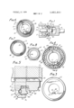
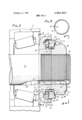
- FIG. 1 shows in cross-section a lock nut assembly according to this invention being fastened by a torquing wrench to a spindle supporting a wheel bearing;
- FIG. 2 is a cross-section view of the assembly of FIG. 1 after removal of the torquing wrench, this being the normal locked position;
- FIG. 3 shows a view taken at line 3-3 of FIG. 2 but without showing the spindle
- FIG. 4 is a view taken at line 4l4 of FIG. 2, without showing the spindle;
- FIG. 5 shows'a detail in cross-section taken at line 5-5 of FIG. 4 under the condition that a wrench is applied as in FIG. 1;
- FIG. 6 is a face view of a washer member used in the assembly of FIGS. 1 and 2;
- FIG. 7 is a face view of an annular ring member used in the assembly of FIGS. 1 and 2;
- FIG. 8 is a face view of a nut used in the assembly of FIGS. 1 and 2;
- FIG. 9 shows a resilient snap ring used in the assembly of FIGS. 1 and 2.
- FIGS. 1 and 2 there is shown part of a spindle 10 on which is mounted a roller bearing assembly 11 fitted within the hub 12 of a wheel, in a wellknown manner.
- a lock nut assembly 13 according to this invention is fitted over and fastened to the outer threaded end 14 of the spindle with a washer member 15 of the assembly abutted against the roller bearing assembly 11.
- the washer 15 has a central hole 16 dimensioned to fit over the spindle 10 with an inwardly protruding key 17 dimensioned to fit into a keyway or groove 18 formed in the surface of spindle 10 at its outer end and extending parallel to the longitudinal axis 19 of the spindle.
- the washer has a circular peripheral portion 20 (seen in FIG.
- annular recess 22 having a base 23 with sidewall portions 24 and 25 which converge toward the base 23.
- the outer end of converging wall 25 of the recess joins cylindrical wall portion 26 of the recess, ahd the outer portion of converging wall 24 connects with an annular ledge 27 which meets hub 21.
- a plurality of serrations 28 protruding radially outward from the hub toward the periphery 20.
- annular ring member 29 Protruding into the recess 22 there is an annular ring member 29 herein referred to as an indicating ring.
- the inside face 30 of this ring member that is the face closest to the bearing 11, is seen inFIG. 7 and the peripheral portion of its outside face is shown in FIG. 4.
- the inside face 30 is planar except for an'annular recess 31 formed therein, this recess having two sides 32 and 33 which converge toward each other to a base 34, best seen in FIG. 2.
- the outer faces 37 extend in a radial direction to meet an outer annular protuberance 38.
- the serrations of ring member 29 are proportioned and dimensioned to be able to mesh with the splines 28 of the washer 15.
- a resiliently expandable and contractable snap ring 39 seen in FIG. 9, having a circular cross-section as shown in FIG. 2 and being in the form of an incomplete circle having abutting ends and 41 which normally meet or nearly meet each other.
- the ring 39 is of resilient material, ordinarily metal, so that the ring is resiliently expandable to a larger circle than that which it has when the ends 40 and 41 abut each other.
- the diameter of ring 39 is such that in its normal contracted position shown in FIGS. 2 and 9 the circumference of the ring meets the 5 junction of side portion 24 of the recess 22 with ledge 27, while another part of the circumference of ring 39 is in contact with the plane surface 30 of the annular ring member as shown in FIG. 2.
- a nut 45 shown as a hex nut having internal threads 46 is adapted to be threaded over the outer end of spindle 10 so that its inner face 47 abuts the outer face of washer 15.
- the inner face of the nut is shown in FIG. 8 and its outer face appears in FIG. 4.
- the portion of the inner face 47 which meets washer 15 is shouldered at 48 and from this shoulder there extend radially outward a plurality of serrations 49 dimensioned so that they can mesh with the serrations 35 of annular ring member 29, thatis, serrations 39 are of substantially the same size and dimensions as serrations 28 of washer 15.
- the hexagonal wrench engaging portion 50 of the nut At the side of serrations 49 opposite that of face 47 of the nut, there is formed the hexagonal wrench engaging portion 50 of the nut. 1
- the nut 45 is held to the above-mentioned assembly of washer 15, annular ring member 29 and snap ring 39 by means of a spring member 51 which is in the form of a resilient strip bent so that one end 52 can be fitted to a shoulder 53 at the outside surface of the nut while the remainder of the spring member extends radially inwardly along the outside face of the nut to a position within the threads of the nut coinciding with the keyway 18 of the spindle where it bends to extend longitudinally within the keyway and through a longitudinal groove 54, best seen in FIG. 6, of key 17 forward of the inner face of the washer where the spring bends at 55 where its end 56 enters into and engages a transverse recess 57 of key 17 as is best seen in FIG. 3.
- the spring 51 is tensioned sufficiently to hold the nut against the washer in the manner shown in FIG. 2.
- the snap ring is in its tensioned condition and the serrations 35 of annular ring member 29 have become disengaged from the serrations of the nut because they have moved so that they do not extend outward as far as the serrations 49 of the nut, although serrations 35 remain in engagement with serrations 28 of the washer.
- the nut can be turned on the spindle while the washer and annular ring member are held fixed relative to the spindle. This turning of the nut can be accomplished by use ofa hollow-ended socket wrench 60 dimensioned to fit the nut. Since the particular nut illustrated herein has a hexagonal form the wrench will be in the form of a hex wrench, and it will'have a handle 61.
- the peripheral portion 62 of the wrench is dimensioned to engage the protuberance 38 of the annular ring member and thereby force the snap ring 39 to the base 23 of the recess as illustrated in FIGS. 1 and 5, and when the snap ring is thus pushed into the recess the wrench can torque the nut at the same time it is holding the snap ring at the base.
- withdrawal of the wrench will release the pressure against the indicator ring so that the resilience of the snap ring will contract its diameter causing the snap ring to slide outward along surface of the recess, thereby pushing the annular ring member 29 outward so that its serrations engage the serrations of the nut while also remaining in engagement with the.
- the annular ring member is provided with radial markings 63 at its rearwardly extending protuberance 38, as seen in FIG. 4, these markings being located opposite the trough of each of its serrations 35 so as to be a visible indication when the elements are'assembled,
- ring member I 29 may be referred to as 'an indicator ring.
- the rear face of the nut is provided with a marking such as a notch 64 to indicate the position of the peak of one of its serrations 49. Since the peaks of the serrations of the nut must enter the troughs of respective serrations of the indicator ring 29, the locking of the nut to the indicator ring must leave the nut marking 64 in registration with one of the indicator ring markings 63. Thus, the markings 63 and 64 are an aid in locking the nut.
- the arrangement is foolproof in that the resilient element maintaining the locked condition is unstrained and in a state of rest when in the locked position. Any shocks to which the resilient element is subjected are not in a direction which readily strains it, and moreover, its structure is such that it is inherently strong and resistant to damage from shock.
- the arrangement is particularly adapted to use as a wheel-bearing nut, but its uses are not so limited. It is applicable for use on bolts and studs in various circumstances where nuts and bolts are used.
- spindle as used herein is not limited to a wheel axle spindle, or the like, but more broadly covers various threaded elements such as bolts on which nuts may be threaded.
- Mechanism for locking a nut on a threaded spindle having a central longitudinal axis comprising:
- a washer having a hub portion adapted to fit over said spindle and a peripheral portion providing an annular recess having a base, between the peripheral and hub portions, and having a plurality of first serrations extending radially outward from said hub portion toward said peripheral portion;
- a threaded nut adapted to thread on the threaded spindle and to abut the washer. and containing a plurality of third serrations extending radially outward and adapted to engage said second serrations;
- Mechanism according to claim 10 in which a spring strip has one of its ends in engagement with the rear of the nut and passes within and through the nut and along the inside of the tongue of the washer and has its other end in engagement with a front surface of the washer, thereby resiliently holding the nut to the washer.
Landscapes
- Engineering & Computer Science (AREA)
- General Engineering & Computer Science (AREA)
- Mechanical Engineering (AREA)
- Details Of Spanners, Wrenches, And Screw Drivers And Accessories (AREA)
- Rolling Contact Bearings (AREA)
- Mounting Of Bearings Or Others (AREA)
- Bolts, Nuts, And Washers (AREA)
Priority Applications (12)
| Application Number | Priority Date | Filing Date | Title |
|---|---|---|---|
| US00400215A US3851690A (en) | 1973-09-24 | 1973-09-24 | Mechanism for securing a nut against loosening |
| DE2443320A DE2443320A1 (de) | 1973-09-24 | 1974-09-10 | Sicherungsmutter |
| SE7411690A SE395517B (sv) | 1973-09-24 | 1974-09-17 | Mekanism for fastsettning av en mutter, sa att den inte lossnar |
| JP49109421A JPS5076459A (it) | 1973-09-24 | 1974-09-21 | |
| CA209,741A CA1016851A (en) | 1973-09-24 | 1974-09-23 | Mechanism for securing a nut against loosening |
| AU73595/74A AU494779B2 (en) | 1973-09-24 | 1974-09-23 | Assembly for securing a nut against loosening |
| FR7432003A FR2244930B1 (it) | 1973-09-24 | 1974-09-23 | |
| IT53162/74A IT1021663B (it) | 1973-09-24 | 1974-09-23 | Perfezionamento nelle disposizioni di bloccaggio per dadi |
| GB4152874A GB1423329A (en) | 1973-09-24 | 1974-09-24 | Mechanism for securing a nut against loosening |
| BR7927/74A BR7407927A (pt) | 1973-09-24 | 1974-09-24 | Mecanismo para travamento de uma porca |
| US05/524,224 US3942570A (en) | 1973-09-24 | 1974-11-15 | Mechanism for securing a nut against loosening |
| AU87713/75A AU8771375A (en) | 1973-09-24 | 1975-12-19 | Mechanism for securing a nut against loosening |
Applications Claiming Priority (1)
| Application Number | Priority Date | Filing Date | Title |
|---|---|---|---|
| US00400215A US3851690A (en) | 1973-09-24 | 1973-09-24 | Mechanism for securing a nut against loosening |
Related Child Applications (1)
| Application Number | Title | Priority Date | Filing Date |
|---|---|---|---|
| US05/524,224 Continuation-In-Part US3942570A (en) | 1973-09-24 | 1974-11-15 | Mechanism for securing a nut against loosening |
Publications (1)
| Publication Number | Publication Date |
|---|---|
| US3851690A true US3851690A (en) | 1974-12-03 |
Family
ID=23582687
Family Applications (1)
| Application Number | Title | Priority Date | Filing Date |
|---|---|---|---|
| US00400215A Expired - Lifetime US3851690A (en) | 1973-09-24 | 1973-09-24 | Mechanism for securing a nut against loosening |
Country Status (9)
| Country | Link |
|---|---|
| US (1) | US3851690A (it) |
| JP (1) | JPS5076459A (it) |
| BR (1) | BR7407927A (it) |
| CA (1) | CA1016851A (it) |
| DE (1) | DE2443320A1 (it) |
| FR (1) | FR2244930B1 (it) |
| GB (1) | GB1423329A (it) |
| IT (1) | IT1021663B (it) |
| SE (1) | SE395517B (it) |
Cited By (28)
| Publication number | Priority date | Publication date | Assignee | Title |
|---|---|---|---|---|
| US3942570A (en) * | 1973-09-24 | 1976-03-09 | Hi-Shear Corporation | Mechanism for securing a nut against loosening |
| US4112992A (en) * | 1977-01-19 | 1978-09-12 | Hi-Shear Corporation | Safety bolt |
| US4501521A (en) * | 1982-04-05 | 1985-02-26 | Smith International, Inc. | Locking fastener assembly |
| DE3507740A1 (de) * | 1984-03-16 | 1985-09-26 | Hi-Shear Corp., Torrance, Calif. | Selbstverriegelnde, loesbare verriegelungsmutter |
| US4557441A (en) * | 1983-12-27 | 1985-12-10 | The Boeing Company | Band tensioning device |
| US4648768A (en) * | 1984-05-15 | 1987-03-10 | Hambric James C | Locknut assembly for high-speed rotary components |
| US4812094A (en) * | 1987-09-24 | 1989-03-14 | Maclean-Fogg Company | Locking fastener assembly for threaded joint |
| US5180265A (en) * | 1992-02-24 | 1993-01-19 | Hi-Shear Corporation | Self locking nut |
| WO1996014515A1 (en) * | 1994-11-02 | 1996-05-17 | Warn Industries, Inc. | Spindle nut and locking device |
| US5533849A (en) * | 1994-07-15 | 1996-07-09 | Hi-Shear Corporation | Self-locking nut for a wheel bearing |
| US5597278A (en) * | 1995-07-24 | 1997-01-28 | Maclean-Fogg Company | Locking fastener assembly for threaded joint |
| US5772373A (en) * | 1994-11-02 | 1998-06-30 | Warn Industries, Inc. | Nut and locking device |
| US20040028504A1 (en) * | 2002-08-07 | 2004-02-12 | Jakubowski, Thaddeus M. | Snap ring retention system |
| US20040096289A1 (en) * | 2001-08-20 | 2004-05-20 | Theodore Bydalek | Fastener assembly |
| US20040258503A1 (en) * | 2001-10-04 | 2004-12-23 | Tuthill James Craig | Spindle nut retainer |
| US20050025604A1 (en) * | 2003-08-01 | 2005-02-03 | Steve Slesinski | Combination lock washer and spindle bearing assembly |
| US6857835B2 (en) | 2002-09-11 | 2005-02-22 | Visteon Global Technologies, Inc. | Wheel end assembly with locking fastener |
| US20050260059A1 (en) * | 2000-10-06 | 2005-11-24 | Lees John S | Wheel nut assembly |
| US7226259B2 (en) * | 2001-08-20 | 2007-06-05 | Maclean-Fogg Company | Locking fastener assembly |
| US7334975B2 (en) | 2001-08-20 | 2008-02-26 | Maclean-Fogg Company | Fastener assembly |
| US7438512B2 (en) | 2001-08-20 | 2008-10-21 | Maclean-Fogg Company | U-bolt assembly |
| US20080296893A1 (en) * | 2007-05-31 | 2008-12-04 | Caterpillar Inc. | Hose assembly with anti-rotational coupling and crimping section |
| US7465135B2 (en) | 2003-11-14 | 2008-12-16 | Maclean-Fogg Company | U-Nut fastening assembly |
| US7497653B2 (en) | 2001-08-20 | 2009-03-03 | Maclean-Fogg Company | Locking fastener assembly |
| US20100266331A1 (en) * | 2009-04-20 | 2010-10-21 | Steven Douglas Peterkort | Retention assembly and a method of operatively securing a hub and wheel assembly to an axle of a selectively movable assembly and method for eliminating frictional interface wear between a bearing and a bearing retention device |
| CN102242773A (zh) * | 2011-07-21 | 2011-11-16 | 无锡利博科技有限公司 | 轴承的支承轴套结构 |
| US20140154028A1 (en) * | 2011-08-02 | 2014-06-05 | Chunguang Pei | Scisssors type expansion bolt |
| US20230358267A1 (en) * | 2022-05-03 | 2023-11-09 | Microtecnica S.R.L. | Actuator lock nut assembly |
Families Citing this family (5)
| Publication number | Priority date | Publication date | Assignee | Title |
|---|---|---|---|---|
| DE2816908C2 (de) * | 1978-04-19 | 1982-02-25 | Messerschmitt-Bölkow-Blohm GmbH, 8000 München | Formschlüssig gesicherte Achsbolzenverbindung |
| SE445762B (sv) * | 1980-06-24 | 1986-07-14 | Volvo Ab | Anordning for att lasa ett mutterelement pa en axeltapp |
| US4505628A (en) * | 1981-03-09 | 1985-03-19 | Meibuhr George C | Bearing locknut |
| GB2256689A (en) * | 1991-04-12 | 1992-12-16 | Marco Benito Pagliuca | Locking of nuts to screw-threaded shanks |
| GB2265683B (en) * | 1992-03-31 | 1995-12-06 | British Aerospace | Locking device for a nut |
Citations (9)
| Publication number | Priority date | Publication date | Assignee | Title |
|---|---|---|---|---|
| US1189656A (en) * | 1915-11-10 | 1916-07-04 | William Bohle | Nut-lock. |
| US1374015A (en) * | 1920-08-17 | 1921-04-05 | Jerruss Joseph | Safety lock-bolt |
| US2332684A (en) * | 1939-10-26 | 1943-10-26 | Kearney & Trecker Corp | Adjusting and locking device |
| US2728895A (en) * | 1954-10-04 | 1955-12-27 | Whitney Blake Co | Self-locking coupling device |
| US2956604A (en) * | 1958-09-30 | 1960-10-18 | John V Crotty | Locking key coupled to lock nut by sliding sleeve |
| US3389735A (en) * | 1967-07-17 | 1968-06-25 | Katz Jack | Retainer assembly |
| US3402750A (en) * | 1965-09-29 | 1968-09-24 | Rolls Royce | Device for locking two members |
| US3581609A (en) * | 1968-12-12 | 1971-06-01 | Eugene C Greenwood | Lock nut assembly and bolt and wrench for use therewith |
| US3670795A (en) * | 1970-06-29 | 1972-06-20 | Wright Barry Corp | Self-locking fastener |
-
1973
- 1973-09-24 US US00400215A patent/US3851690A/en not_active Expired - Lifetime
-
1974
- 1974-09-10 DE DE2443320A patent/DE2443320A1/de not_active Ceased
- 1974-09-17 SE SE7411690A patent/SE395517B/xx unknown
- 1974-09-21 JP JP49109421A patent/JPS5076459A/ja active Pending
- 1974-09-23 CA CA209,741A patent/CA1016851A/en not_active Expired
- 1974-09-23 FR FR7432003A patent/FR2244930B1/fr not_active Expired
- 1974-09-23 IT IT53162/74A patent/IT1021663B/it active
- 1974-09-24 BR BR7927/74A patent/BR7407927A/pt unknown
- 1974-09-24 GB GB4152874A patent/GB1423329A/en not_active Expired
Patent Citations (9)
| Publication number | Priority date | Publication date | Assignee | Title |
|---|---|---|---|---|
| US1189656A (en) * | 1915-11-10 | 1916-07-04 | William Bohle | Nut-lock. |
| US1374015A (en) * | 1920-08-17 | 1921-04-05 | Jerruss Joseph | Safety lock-bolt |
| US2332684A (en) * | 1939-10-26 | 1943-10-26 | Kearney & Trecker Corp | Adjusting and locking device |
| US2728895A (en) * | 1954-10-04 | 1955-12-27 | Whitney Blake Co | Self-locking coupling device |
| US2956604A (en) * | 1958-09-30 | 1960-10-18 | John V Crotty | Locking key coupled to lock nut by sliding sleeve |
| US3402750A (en) * | 1965-09-29 | 1968-09-24 | Rolls Royce | Device for locking two members |
| US3389735A (en) * | 1967-07-17 | 1968-06-25 | Katz Jack | Retainer assembly |
| US3581609A (en) * | 1968-12-12 | 1971-06-01 | Eugene C Greenwood | Lock nut assembly and bolt and wrench for use therewith |
| US3670795A (en) * | 1970-06-29 | 1972-06-20 | Wright Barry Corp | Self-locking fastener |
Cited By (36)
| Publication number | Priority date | Publication date | Assignee | Title |
|---|---|---|---|---|
| US3942570A (en) * | 1973-09-24 | 1976-03-09 | Hi-Shear Corporation | Mechanism for securing a nut against loosening |
| US4112992A (en) * | 1977-01-19 | 1978-09-12 | Hi-Shear Corporation | Safety bolt |
| US4501521A (en) * | 1982-04-05 | 1985-02-26 | Smith International, Inc. | Locking fastener assembly |
| US4557441A (en) * | 1983-12-27 | 1985-12-10 | The Boeing Company | Band tensioning device |
| DE3507740A1 (de) * | 1984-03-16 | 1985-09-26 | Hi-Shear Corp., Torrance, Calif. | Selbstverriegelnde, loesbare verriegelungsmutter |
| US4648768A (en) * | 1984-05-15 | 1987-03-10 | Hambric James C | Locknut assembly for high-speed rotary components |
| US4812094A (en) * | 1987-09-24 | 1989-03-14 | Maclean-Fogg Company | Locking fastener assembly for threaded joint |
| AU594918B2 (en) * | 1987-09-24 | 1990-03-15 | Maclean-Fogg Company | Locking fastener assembly for threaded joint |
| US5180265A (en) * | 1992-02-24 | 1993-01-19 | Hi-Shear Corporation | Self locking nut |
| US5533849A (en) * | 1994-07-15 | 1996-07-09 | Hi-Shear Corporation | Self-locking nut for a wheel bearing |
| WO1996014515A1 (en) * | 1994-11-02 | 1996-05-17 | Warn Industries, Inc. | Spindle nut and locking device |
| US5618143A (en) * | 1994-11-02 | 1997-04-08 | Warn Industries, Inc. | Spindle nut and locking device |
| US5772373A (en) * | 1994-11-02 | 1998-06-30 | Warn Industries, Inc. | Nut and locking device |
| US5597278A (en) * | 1995-07-24 | 1997-01-28 | Maclean-Fogg Company | Locking fastener assembly for threaded joint |
| US20050260059A1 (en) * | 2000-10-06 | 2005-11-24 | Lees John S | Wheel nut assembly |
| US7172380B2 (en) * | 2000-10-06 | 2007-02-06 | Wheelsure Technologies Limited | Wheel nut assembly |
| US8011866B2 (en) | 2001-08-20 | 2011-09-06 | Maclean-Fogg Company | Locking fastener assembly |
| US7497653B2 (en) | 2001-08-20 | 2009-03-03 | Maclean-Fogg Company | Locking fastener assembly |
| US20040096289A1 (en) * | 2001-08-20 | 2004-05-20 | Theodore Bydalek | Fastener assembly |
| US7226259B2 (en) * | 2001-08-20 | 2007-06-05 | Maclean-Fogg Company | Locking fastener assembly |
| US7334975B2 (en) | 2001-08-20 | 2008-02-26 | Maclean-Fogg Company | Fastener assembly |
| US7438512B2 (en) | 2001-08-20 | 2008-10-21 | Maclean-Fogg Company | U-bolt assembly |
| US20040258503A1 (en) * | 2001-10-04 | 2004-12-23 | Tuthill James Craig | Spindle nut retainer |
| US6896463B2 (en) * | 2001-10-04 | 2005-05-24 | Dexter Axle Company | Spindle nut retainer |
| US6773214B2 (en) * | 2002-08-07 | 2004-08-10 | The Boeing Company | Snap ring retention system |
| US20040028504A1 (en) * | 2002-08-07 | 2004-02-12 | Jakubowski, Thaddeus M. | Snap ring retention system |
| US6857835B2 (en) | 2002-09-11 | 2005-02-22 | Visteon Global Technologies, Inc. | Wheel end assembly with locking fastener |
| US20050025604A1 (en) * | 2003-08-01 | 2005-02-03 | Steve Slesinski | Combination lock washer and spindle bearing assembly |
| US6976816B2 (en) * | 2003-08-01 | 2005-12-20 | Dana Corporation | Combination lock washer and spindle bearing assembly |
| US7465135B2 (en) | 2003-11-14 | 2008-12-16 | Maclean-Fogg Company | U-Nut fastening assembly |
| US20080296893A1 (en) * | 2007-05-31 | 2008-12-04 | Caterpillar Inc. | Hose assembly with anti-rotational coupling and crimping section |
| US9388923B2 (en) * | 2007-05-31 | 2016-07-12 | Caterpillar Inc. | Hose assembly with anti-rotational coupling and crimping section |
| US20100266331A1 (en) * | 2009-04-20 | 2010-10-21 | Steven Douglas Peterkort | Retention assembly and a method of operatively securing a hub and wheel assembly to an axle of a selectively movable assembly and method for eliminating frictional interface wear between a bearing and a bearing retention device |
| CN102242773A (zh) * | 2011-07-21 | 2011-11-16 | 无锡利博科技有限公司 | 轴承的支承轴套结构 |
| US20140154028A1 (en) * | 2011-08-02 | 2014-06-05 | Chunguang Pei | Scisssors type expansion bolt |
| US20230358267A1 (en) * | 2022-05-03 | 2023-11-09 | Microtecnica S.R.L. | Actuator lock nut assembly |
Also Published As
| Publication number | Publication date |
|---|---|
| CA1016851A (en) | 1977-09-06 |
| DE2443320A1 (de) | 1975-04-03 |
| AU7359574A (en) | 1976-03-25 |
| FR2244930A1 (it) | 1975-04-18 |
| SE395517B (sv) | 1977-08-15 |
| BR7407927D0 (pt) | 1975-09-16 |
| SE7411690L (it) | 1975-03-25 |
| FR2244930B1 (it) | 1980-07-04 |
| JPS5076459A (it) | 1975-06-23 |
| IT1021663B (it) | 1978-02-20 |
| GB1423329A (en) | 1976-02-04 |
| BR7407927A (pt) | 1975-09-16 |
Similar Documents
| Publication | Publication Date | Title |
|---|---|---|
| US3851690A (en) | Mechanism for securing a nut against loosening | |
| US3942570A (en) | Mechanism for securing a nut against loosening | |
| US7927052B1 (en) | Locking axle nut | |
| US5180265A (en) | Self locking nut | |
| US4462731A (en) | Split nut assembly | |
| US3762455A (en) | Lock nut | |
| US3844323A (en) | Split lock ring | |
| US5207543A (en) | Connecting device with a nut and bolt to prevent loosening and losing the nut | |
| US4971501A (en) | Self-locking, releasable lock nut | |
| US4742702A (en) | Anti-theft device for a wheel lug nut | |
| CA2376542C (en) | Locking fastener assembly | |
| JPH0660654B2 (ja) | 緩み止め締結具組立体 | |
| US5139381A (en) | Slide-fit nut | |
| US5118237A (en) | Quick application/release nut with engagement indicator | |
| US3918779A (en) | System for securing roller bearings | |
| EP0824635A1 (en) | Self-locking bearing nut | |
| US4557652A (en) | Lockable nut | |
| US4084630A (en) | Locking ring for a castellated nut | |
| EP0399235B1 (en) | Bolt and nut lock assembly | |
| US3295578A (en) | Fastening device | |
| US5304021A (en) | Screw threaded locking bolt assembly | |
| US2313763A (en) | Nut assembly | |
| US3705524A (en) | Lock nut assembly and bolt and wrench for use therewith | |
| US5015133A (en) | Universal nut | |
| US3378288A (en) | Blind bolt and method for its use |
Legal Events
| Date | Code | Title | Description |
|---|---|---|---|
| AS | Assignment |
Owner name: COMERICA BANK-CALIFORNIA, CALIFORNIA Free format text: HI-SHEAR CORPORATION;ASSIGNOR:HI-SHEAR CORPORATION;REEL/FRAME:009445/0149 Effective date: 19980826 |
|
| AS | Assignment |
Owner name: HI-SHEAR CORPORATION, CALIFORNIA Free format text: RELEASE BY SECURED PARTY;ASSIGNOR:COMERICA BANK;REEL/FRAME:018951/0191 Effective date: 20070220 |
|
| AS | Assignment |
Owner name: HI-SHEAR CORPORATION, CALIFORNIA Free format text: RELEASE BY SECURED PARTY;ASSIGNOR:COMERICA BANK;REEL/FRAME:018951/0913 Effective date: 20070220 |