US3846984A - Temperature differential fluid motor - Google Patents
Temperature differential fluid motor Download PDFInfo
- Publication number
- US3846984A US3846984A US00464823A US46482374A US3846984A US 3846984 A US3846984 A US 3846984A US 00464823 A US00464823 A US 00464823A US 46482374 A US46482374 A US 46482374A US 3846984 A US3846984 A US 3846984A
- Authority
- US
- United States
- Prior art keywords
- chamber
- chambers
- liquid
- vapor
- moveable
- Prior art date
- Legal status (The legal status is an assumption and is not a legal conclusion. Google has not performed a legal analysis and makes no representation as to the accuracy of the status listed.)
- Expired - Lifetime
Links
Images


Classifications
-
- F—MECHANICAL ENGINEERING; LIGHTING; HEATING; WEAPONS; BLASTING
- F03—MACHINES OR ENGINES FOR LIQUIDS; WIND, SPRING, OR WEIGHT MOTORS; PRODUCING MECHANICAL POWER OR A REACTIVE PROPULSIVE THRUST, NOT OTHERWISE PROVIDED FOR
- F03G—SPRING, WEIGHT, INERTIA OR LIKE MOTORS; MECHANICAL-POWER PRODUCING DEVICES OR MECHANISMS, NOT OTHERWISE PROVIDED FOR OR USING ENERGY SOURCES NOT OTHERWISE PROVIDED FOR
- F03G4/00—Devices for producing mechanical power from geothermal energy
- F03G4/074—Safety arrangements
Definitions
- ABSTRACT The invention describes a unit pair of chambers with means of obtaining a temperature differential between the chambers,
- the chambers contain a low boiling point fluid defining a liquid phase and a vapor phase.
- By closing and opening of a communication between vapor phases of the chambers cyclic differences in vapor pressure between the chambers is obtained.
- At least one of said chambers is provided with a moveable wall portion which responds to changes in the vapor pressure in the chamber.
- This movable wall also controls the opening between vapor phases of chambers. Controls and conduits are provided to return the condensed liquid from cold to warm chamber, and the return of moveable portion to its starting position. By means of proper linkages, the moveable wall is translated into useful work.
- the differential temperature fluid motor of this invention comprises a pair of interconnected chambers which are sealed against any external environment and wherein provision is made for obtaining a small temperature differential between the respective chambers so that one is relatively warmer than the other.
- An activating fluid preferably one having a low boiling point, is disposed in the respective chamber to define a liquid level to separate the respective chambers into a vapor chamber portion and a liquid chamber portion.
- the chamber kept at the relatively warmer temperature serves as an evaporator, while the colder chamber functions as a condensor.
- One or both of the chambers is provided with a moveable portion.
- the respective vapor phases and liquid phases of the chambers are connected into communication by connecting conduits.
- a valve is disposed in the vapor conduit which is rendered responsive to a moveable wall portion of one of the chambers to cycle the changes in pressure occuring within the respective chamber.
- a one way valve is interposed in the liquid conduit to permit the flow of liquid from the colder chamber to the warmer chamber only.
- Cyclical changes in vapor pressure between the two chambers is attained by periodically opening and closing the vapor valve so that the pressure changes occuring in one of the chambers results in the displacement of the moveable wall thereof; the movement of which is translated into work.
- pressure within the warm chamber is increased as pressure in the cold chamber is diminished by condensation.
- the build up pressure within the warm chamber upon overcoming the resistance to movement of the moveable wall portion effects displacement thereof.
- the pressure within the warm chamber is diminished and the pressure within the cold chamber increased.
- the vapor valve being rendered responsive to the displacement of the moveable wall portion effects cyclical changes in pressure which results in periodic displacement of the associated moveable wall portion which is translated into useful work.
- the temperature differential of the respective chambers can be achieved in any of several ways; e.g., evaporation, submersion, heating, cooling, and the like. Means to return displaced wall to its starting position are included.
- An object of this invention is to provide an apparatus which utilizes water as the motivating force for the production of useful work.
- An object of this invention is to provide an apparatus which utilizes natural thermal environmental energy to produce useful work.
- Another object of this invention is to provide a fluid motor which can be readily operated at relatively low temperatures.
- Another object of this invention is to provide a fluid motor in which the energy of liquid evaporation is utilized for the production of useful work.
- Another object of this invention is to utilize the temperature differential between two natural environments for the production of useful work.
- Another object of this invention is to utilize a fluid motor in which ice is utilized as a fuel source for the production of useful work.
- Another object of this invention is to provide a fluid motor which can be readily utilized with any type of dombustible material.
- a major feature of this invention is the provision of a motor which can utilize readily available environment differences of temperature for the production of useful work. It thus utilizes a practically unlimited and previously untapped source of environmental energy for the production of useful work.
- Another feature of this invention resides in the provision of a fluid motor having a pair of closed volumes in which the energy of cyclical evaporation and condensing of the liquid contained therein is utilized to produce useful work.
- Another feature of this invention resides in a fluid motor in which the external environmental forces are utilized to maintain a temperature differential between the respective chambers.
- FIG. 1 is a cross sectional view of a fluid motor embodying the present invention.
- FIG. 2 is a cross sectional view of a modified form of the invention.
- FIG. 3 is a cross sectional view of still another modified form of the invention.
- FIG. 4 is a cross sectional view of still another embodiment of the invention.
- FIG. 5 is a fragmentary cross sectional view of a modified form of evaporator chamber, for use in the fluid motor embodying the present invention.
- FIG. 6 is a fragmentary cross sectional view of a modified form of condensor chamber utilized in the fluid motor of this invention.
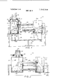
- FIG. 1 a temperature fluid motor 10 embodying the present invention.
- a support or frame 11 is provided for supporting thereon a chamber 12 which functions as an evaporator as will be hereinafter described.
- the chamber or evaporator 12 is defined by circumscribing sidewalls 13 connected to a top wall 13A and bottom wall 13B.
- the bottom wall 13B of the evaporator or chamber 12 is connected to the circumscribing side walls 13 by means of a compressable and/or expandable bellows joint 15.
- the arrangement is such that the bottom wall 13B can be readily moved within the limits of the expansion and contraction of the bellows joint 15 in a reciprocating, up and down, direction.
- a supply of activating fluid 16 Disposed within the evaporator or chamber 12 is a supply of activating fluid 16, which is a liquid having a low boiling point.
- the activating liquid 16 thus defines a liquid level 16A to separate chamber 12 into liquid chamber portion 12A and a vapor chamber portion 125.
- Chamber 18 Suitably supported on the frame structure 11 is another chamber 18 which functions as a condensor, as will be hereinafter described.
- Chamber 18 or condensor has circumscribing sidewalls l9 and an interconnected top wall [9A and bottom wall 19B. As shown,
- the bottom wall 19B is attached to the circumscribing side walls 19 by an expandable and/or compressable bellows joint 20.
- the arrangement is such that the bottom wall 19B of chamber 18 can be readily moved in a reciprocating or up and down movement within the limits of expansion and contraction of the bellows joint 20.
- the external surfaces of the condensor chamber 18 is covered with a wick like material 21 which when wetted with a suitable liquid, e.g., water, effects the cooling of the condensor chamber 18 by evaporation as will be hereinafter described.
- a suitable liquid e.g., water
- Chamber or condensor 18 also contains a supply of activating fluid 16 wherein the liquid level 16A thereof defines a liquid chamber portion 18A and a vapor chamber portion 18B.
- a connecting conduit 24 Connecting the liquid chamber portion 18A of the condensor chamber 18 to the liquid chamber portion 12A of the evaporator chamber 12 is a connecting conduit 24.
- a valve means is interposed in conduit 24 to regulate the flow of liquid 16 between the respective liquid chamber portions 12A and 18A of chambers 12 and 18.
- the valve 25 is so constructed so that it allows for only one way movement of the liquid; i.e., the liquid 16 is free to move from the liquid chamber portion 18A of the condensor chamber 18 to the liquid chamber portion 12A of the evaporator chamber 12. Thus valve 25 prohibits any reverse movement of fluid 16 from the liquid chamber portion 12A to the liquid chamber portion 18A.
- the vapor chamber portion 128 of the evaporator chamber 12 and the vapor chamber portion 18B of the evaporator 18 are connected into communication by a vapor conduit 26. Controlling the flow of vapor through conduit 26 is a valve 27 which is normally closed.
- the vapor valve 27 is periodically actuated between an open and closed position automatically and in response to the movement of the bottom wall 198 of the condensing chamber 19 as will be herein described.
- a valve actuator 28 is interconnected between the bottom wall 198 of condcnsor chamber 18 and the valve 27. The arrangement is such that upon the upper movement of the bottom wall 198 of chamber 18 will affect an opening of valve 27 as will be herein after described. Downward movement of the bottom wall 19B will effect a closing of valve 27.
- a resevoir or tank 29 Supported on top of the condensing chamber 18 is a resevoir or tank 29 which is adapted to contain a supply of cooling liquid 30 as for example, water.
- Branch conduits 31 are connected to the tank or resevoir 29 for directing the cooling water 30 from the tank or resevoir 29 onto the outer wick coating 21 of the conensing chamber 18.
- suitable valve means 32 may be interposed in the respective branch conduits 31 for controlling the flow of cooling water onto the wick coating 21.
- a lever 33 is disposed below the respective moveable wall portions 13B and 193.
- the lever 33 is supported intermediate the ends thereof on a fulcrum 34.
- the opposed arm position 33A, 33B of the lever 33 thus rotates or see'saw about fulcrum 34.
- Arm extensions 37 and 38 extend from the end portions 33A, 33B of the lever 33 whereby the arm extensions 37 and 38 are disposed continuous to the respective moveable bottom walls 13B and 19B of containers 12 and 19. Accordingly, as shown the bottom walls 13B and 198 seat on or are in contact with the arm extensions 38 and 37, respectively.
- valves 32 With valves 32 opened, water is withdrawn from the resevoir or tank 29, e.g., by gravity, and drips onto the wick surface 21 of the condensor chamber 18 to wet the same.
- the natural evaporation of the cooling water from the wick surface 21 effects a cooling of the chamber 18 to several degrees below the ambient or environ mental temperature of chamber 12. This results in a temperature differential between chambers 12 and 18.
- valve 27 With valve 27 in its closed position, the vapor chamber portion 128 of chamber 12 is separated from the vapor portion chamber 188 of chamber 18. Thus the differences in temperature occuring between chamber 12 and 18 will result in a vapor pressure differential between chambers 12 and 18.
- the activating fluid 16 has a low boiling point, it will readily volutilize within chamber 12 so as to increase the vapor pressure in the relatively warmer chamber 12.
- a vapor pressure force is exerted on the bottom wall 138 of the warmer chamber 12.
- the bottom wall 13B will therefore exert a force upon the extension arm 37 of lever arm 33.
- the bottom wall 13B moves downwardly, it will simultaneously effect displacement of the lever arm 33B downwardly. This will result in an upward movement of lever arm 33A and its extension 38. This in turn causes the bottom wall 19B to be displaced upwardly to compress the bellows joint 20 of chamber 18.
- valve actuator 27A Upon the downward movement of the bottom wall 19B of the chamber 18, and as the bottom wall 19B approaches its lower limit of travel, the valve actuator 27A will cause the closing of valve 27. Thus the vapor which has entered into container 18 from container 12 due to the relatively colder temperature of chamber 18 will subsequently condense to return to its liquid form. This will result in a reduction of the vapor pressure in container 18. Conversely the vapor pressure in the relatively warmer evaporating chamber 12 is regenerated by the evaporation of the activating fluid 16. This increase in pressure forces the bottom wall 138 downwardly to repeat the cycle of operation described.
- transmission member 39 is illustrated as being connected to the moveable wall portion 198, it will be understood that the transmission member 39 may be associated with bottom wall 138 of chamber 12 and/or a transmission member may be connected to both bottom walls 135 and bottom wall 198 of chambers 12 and 18.
- FIG. 2 illustrates another embodiment of the invention.
- the construction of the temperature differential motor 110 is similar in all respects to that described with respect to FIG. 1 except that the lever 33 has been omitted.
- the bottom wall 1138 of chamber 112 is moveably attached to the sidewalld 1138 of chamber 112 by an imperforate expansion means as for example, a bellows expansion joint 11S, whereby the inherent resiliency of the bellows joint 115 functions as a tension spring.
- the arrangement is such that the bellows joint 11S normally exerts a predetermined spring force on the bottom wall 1138. This predetermined spring force is designed to keep the bottom wall 1138 in a normally upward position or folded bellows position.
- a force transmission member 139 Attached to the outside of the bottom wall 1133 is a force transmission member 139.
- the extened end of the transmission member 139 is suitably connected to a mechanical means or suitable linkage means for translating the rhythmic, reciprocating, up and down movement of the bottom wall 113B into either a rotary or linear motion, as may be required to effect the production of useful work.
- the bottom wall 93 of the container 118 is inmoveably attached to the side walls 119 of the condensing chamber 118.
- Valve 127 and valve actuator 128 are rendered responsive to the movement of the bottom wall 113B, as hereinbefore described, so as to effect the periodic or cyclical opening and closing of the valve 127.
- structure of FIG. 2 is identical to that described with respect to FIG. 1. In operation the embodiment of FIG. 2 operates as follows:
- valve actuator 128 is displaced accordingly to cause valve 127 to open the communication between the respective vapor chamber portions 1128 and 1185 of chambers 112 and 118, respectively. Opening of valve 127 causes the vapor pressure chamber 1198 of chamber 118 to be placed into communication with chamber portion 1128 of chamber 112. In doing so, the pressure exerted against the bottom wall 1135 of chamber 112 is reduced.
- valve actuator 128 to effect a closing of valve 127.
- valve 127 With valve 127 closed, new vapor will be generated in the evaporator chamber 112 through natural evaporation of the actuating fluid 116 to again increase the pressure acting on wall 113B to result in a downward displacement of the bottom wall 1138.
- the vapor which had entered the condensor chamber 118 from the evaporator chamber 112 will condense to form a liquid as a result of the cooled temperatures occuring within the condensor chamber 118.
- this condensation of the activating fluid will decrease the vapor pressure within the condensor chamber 118 and increase the amount of liquid 116 within the condensor chamber 118.
- the liquid 116 will begin to flow from the condensor chamber 118 to the evaporator chamber 112 through conduit 124.
- flow of fluid 116 from the condensor chamber 118 to the evaporator chamber 112 is effected by gravity, and results in equalizing the liquid level 116A in the respective chambers 112 and 118. This will occur during the opening of conduit 126 which results in a temporary equalization of vapor pressure upon the fluids in the evaporator 112 and condensor 118.
- the condensed liquid will thus be continuously returned from the condensor 118 to the evaporator 112 during the repeated cycles of motor operation.
- bottom wall 1133 will effect a corresponding movement of the transmis sion member 139.
- the reciprocating movement of the transmission member 139 is readily translated into useful work, as hereinbefore described, through suitable linkage systems into either a rotary or a linear move ment.
- the moving parts which respond to changes in vapor pressure may also consist of the bottom wall 1198 of condensor 118 instead of the bottom wall 1138 of the evaporator chamber 112 and- /or both bottom walls 1138 and 1198 may be moveably supported.
- the moveable parts may likewise consit not only of the bottom wall portion of the respective chambers, but also may consist of any wall portion of the chamber.
- the arrangement requires that the moveable parts, e.g., the moveable walls in any of the variations to be rendered responsive to changes in vapor pressures which occur during the opening and closing of the vapor valve 127 which controls the flow of vapor between the respective vapor chamber portions of chambers 112 and 118.
- FIG. 3 illustrates another form of the invention which is adpated to operate on a temperature differential occuring between an ambient atmosphere and ambient water environment wherein the temperature of the ambient water W is colder than of the ambient atmosphere.
- This embodiement 210 is particularly adapted for use under conditions in which the differential temperature fluid motor is used in the proximity of a large body of water W as for example, a lake or a sea. This version can be utilized on a boat traveling through such body of water W.
- the differential temperature apparatus 210 is identical to that described with respect to FIG. 2 with the following noted exceptions.
- the cold or condensing chamber 218 is situated at a lower level than the evaporating chamber 212 whereby the condensing chamber 218 is submerged in a body of water W to be thereby cooled. in this arrangement, the wick covering of FIGS. 1 and 2 of the condensor chamber as hereinbefore described, is omitted.
- a pump 240 is disposed in the liquid conduit to pump the condensate between liquid chamber portion 218A of the condensor chamber 218 to the liquid chamber portion 212A of the evaporator chamber 212. If desired, the pump 240 may be activated by the movement of the bottom wall 2138 of the evaporator chamber 212 through a suitable interconnecting linkage means 241.
- a pressure or one way valve 225 is disposed in conduit 224 to open in response to the outside pressure of the pump, but not in response to the vapor pressure occuring within chamber 212.
- the pressure valve functions as a one way valve which permits the flow of liquid 216 from chamber 218 to chamber 212 only.
- valve 227 With valve 227 closed, the respective vapor chamber portions 212B and 2185 of the evaporator chamber and condensing chamber, respectively, are separated. As chamber 212 is warmed by the external ambient environmental temperatures, the liquid 216 contained therein will tend to evaporate thereby increasing the vapor pressure within chamber 212 as hereinbefore described. Cold chamber 218 being cooled by the environmental or external temperature of the colder body of water results in a temperature differential occuring between the evaporator 212 and the condensor 218. This temperature differential results in a vapor differential between chambers 212 and 218; i.e., the vapor pressure in chamber 212 will exceed the vapor pressure in the cold chamber 218, when valve 227 is closed.
- the liquid pressure of chamber 212 will thereby exert a vapor pressure upon the moveable wall 2138 of the chamber 212.
- the bottom wall 213B will move downwardly in response increasing to this vapor pressure.
- the bottom wall 213B Upon downward movement of the bottom wall 213B, and when bottom Wall 2138 reaches its lower limit of travel, the bottom wall 213B lowers the valve actuator 228 to thereby opens valve 227 and place chamber 212 into communication with the vapor chamber portion 218B of the condensor 218.
- FIG. 4 is similar to that described with respect to FIG. 3 except that this embodiment 310 is adapted to function in a water-atmosphere environment in which the temperature of the water W is warmer than that of the atmosphere A.
- the warm chamber or evaporating chamber 312 is submerged in water W and the cold or condensing chamber 318 is placed at the higher elevation so as to be cooled by the cooler ambient atmosphere A.
- the lower wall 313B of the evaporator chamber 312 is fixedly secured to the circumscribing sidewalls 313 of the chamber 312.
- the upper wall 313A of the evaporator 312 is moveably attached to the sidewalls 313 through the means of an imperforate bellows expansion joint 315 wherein the inherent resiliency of the bellows joint 315 functions as a tension spring.
- the arrangement is such that when the vapor pressure in the evaporator chamber 312 and the condensor chamber 318 are equal, the spring force in bellows 315 causes the bellows to be disposed in its collapsed or contracted position whereby the upper wall 313A is maintained in its most downwardly position.
- the spring force of bellows 315 will be overcome and the associated upper wall 313A moves to its upper most position upon the development of a vapor pressure within the evaporator chamber 312 sufficient to overcome the resistance of the bellows joint 315, as hereinbefore described.
- the force transmission member 339 which is operatively connected the moveable top wall portion 313A thus moves up and down as the moveable wall 313A is reciprocated.
- the extended end of the transmission member 339 is operatively connected by mechanical means or linkages whereby the movement ofthe moveable wall 313A can be translated into useful work.
- Pump 240 of FIG. 3 is omitted from this embodiment 310 and a valve 325 is located in the liquid conduit 324. This valve 325 allows the liquid to flow from the condensor 318 to the evaporator 312 to occur by gravity.
- the operation of the embodiment illustrated by FIG. 4 is as follows:
- the evaporator 312 is kept at the warmer water temperature by submerging it in the relatively warmer body of water W.
- Valve 327 is normally closed to separate the vapor chamber portion 31213 of the evaporator 312 from the vapor chamber portion 31813 of the condenser 318.
- the vapor pressure in the evaporator increases due to the low boiling point of the activating liquid 316, will exert a pressure upon the moveable wall 313A of the evaporator to overcome the spring force of bellows 315. Since the top wall 313A is moveable, it moves upwardly to respond to any build up of pressure oecuring within the evaporator 312.
- valve 327 is opened by upward movement of the valve actuator 328. This opens conduit 326 and causes the vapor portion 318B of the condenser 318 to be placed into communication with the vapor portion 3128 of the evaporator chamber 312.
- the vapor which has previously entered into the condensor 318 from the evaporator 312 will condense to form liquid as a result of the cooler temperature maintained on the condensor.
- the condensed liquid will collect in the bottom of the condensor 318 and be returned to the evaporator by gravity through the one way valve 325 in conduit 325.
- the up and down movement of the upper wall 313A will effect a correspond- 6 ing movement of the transmission member 339. This movement as hereinbefore described is translated into either rotary or linear movement by suitable mechanical kinkatures.
- FIG. 5 illustrates a modified evaporating chamber 400 wherein an additional means may be utilized for obtaining the temperature differential between the evaporating chamber 400 and an associated condensing chamber.
- a heating means 50 is provided to impart heat to the activating liquid 416.
- the heater is an electric resistance heater which is opcrativcly connected into an electric circuit 51 to a source of electrical supply 52, as for example, a battery. generator, line current.
- a thermostat 52 may be included in the circuit 51. Walls of chamber are surrounded by a covering insulating material 53 so as to prohibit any heat loss to the external environment.
- the means to heat the liquid supply in chamber 400 may consist of other heating devices without departing from the invention. Thus, it may consist of a means for controlled burning of combustible materials in the environment of chamber 400 for raising the temperature of liquid 416.
- FIG. 6 represents a modification of a condesning chamber 60.
- the condensing chamber is adapted to be cooled by immersion in a container containing a cold fluid.
- the inside space of an outer container 61 encloses the condensing chamber 60.
- Supports 62 extend from the bottom wall 63 of the other container 61 to space the outer container 61 from the condensing chamber 60.
- walls of outer container 61 be made of good heat insulating materials so as to minimize any transfer of heat from the external environment to the container 61.
- Container 61 is adapted to hold a cold liquid or other cooling material, as for example, ice 64.
- the condenser 60 is adapted to be submerged in the icewater or cooling media in container 61.
- the chamber 60 thus rests on supports 62 so as to allow circulation of the cooling media on the outside of the bottom wall chamber 60.
- Chamber 60 is also immovably fastened to the wall of the outer container 61 by braces 65 so as to prevent the upper movement of the condensor 60 by the buoyant forces of the cooling liquid or media 64 within the container 61.
- a wick covering 21 as in FIG. 1 is omitted from chamber 61] and the walls of chamber 60 are constructed of good heat conducting material to allow maximum cooling of the chamber 60 by the surrounding fluid 64.
- hopper 66 are disposed above container 61 for feeding the cooling medium into the space 67 between the condensor 60 and the outer container 61.
- a temperature differential fluid motor comprising at least one relatively warm and at least one relatively cold chamber
- a supply of liquid disposed in said chambers dividing the chambers into a vapor chamber portion and a liquid chamber portion.
- At least one of said chambers having a moveable portion adapted to be displaced from an initial position when the vapor pressure within said chamber reaches one predetermined limit
- vapor control means for controlling the flow of vapor between said cold and warm chamber to create periodic pressure differential between said chambers, said control means being operatively associated with said moveable portion of one of said chambers,
- liquid connecting means for placing the liquid portions of the respective cold and warm chambers into communication
- liquid control means for controlling flow of liquid between said chambers
- a force transmission member connected to said moveable portion for translating the movement of said moving portion into useful work.
- means for returning moveable portion to its initial position include spring means acting on said moveable portion to impart a predetermined resistance to the movement of said moveable portion.
- both warm and cold chamber contain a moveable portion
- said means for returning moveable portions to their initial position include a fulcrumed level, said lever having its opposed end portions operatively associated with moveable portions of said chambers.
- the invention as defined in claim 4 including means to affect air compression in a chamber for affecting the position moving parts.
- liquid control means for controlling flow of liquid between said chamber include pump means.
- means for controlling the flow of vapor between chambers include valve means operatively associated with said vapor connecting means for controlling the flow of vapor between said chambers,
- liquid control means for controlling flow of liquid between said chambers include one way valve means, said valve means being operative to permit the liquid to flow from said chamber to said warm Chamber but restricts flow of liquid from said warm to said cold chamber.
- said means for obtaining a temperature differential includes wetting exterior portion of one of said chambers and means for wetting said surface whereby said one chamber is cooled by evaporation.
- said means for obtaining said temperature differential including a heating means for heating one of said chambers.
- the invention as defined in claim 1 including a container for submerging at least one of said chambers in a water bath.
- means for obtaining a temperature differential between said chambers include means for submerging at least one of said chambers in a liquid body.
Landscapes
- Engineering & Computer Science (AREA)
- Chemical & Material Sciences (AREA)
- Combustion & Propulsion (AREA)
- Life Sciences & Earth Sciences (AREA)
- Sustainable Energy (AREA)
- Mechanical Engineering (AREA)
- General Engineering & Computer Science (AREA)
- Thermotherapy And Cooling Therapy Devices (AREA)
- Cooling Or The Like Of Semiconductors Or Solid State Devices (AREA)
- Engine Equipment That Uses Special Cycles (AREA)
Abstract
The invention describes a unit pair of chambers with means of obtaining a temperature differential between the chambers, The chambers contain a low boiling point fluid defining a liquid phase and a vapor phase. By closing and opening of a communication between vapor phases of the chambers, cyclic differences in vapor pressure between the chambers is obtained. At least one of said chambers is provided with a moveable wall portion which responds to changes in the vapor pressure in the chamber. This movable wall also controls the opening between vapor phases of chambers. Controls and conduits are provided to return the condensed liquid from cold to warm chamber, and the return of moveable portion to its starting position. By means of proper linkages, the moveable wall is translated into useful work.
Description
United States Patent [1 1 Siegel [Ill 3,846,984
[ Nov. 12, 1974 TEMPERATURE DIFFERENTIAL FLUID MOTOR [76] Inventor: Israel Siegel, 351 W. 71st St., New
York, NY. 10023 [22] Filed: Apr. 29, 1974 [2]] Appl. No.: 464,823
{52] U.S. Cl 60/509, 60/5l2, 60/531 [51] Int. Cl. Ftllk 27/00, F03g 7/06 [58] Field of Search 60/508, 509, 512, 5 l6,
[56] References Cited FOREIGN PATENTS OR APPLICATIONS 810,662 3/1959 Great Britain 60/531 Primary ExaminerMartin P. Schwadron Assistant ExaminerAllen M. Ostrager Attorney, Agent, or Fr'rm-Philip G. Hilbert [57] ABSTRACT The invention describes a unit pair of chambers with means of obtaining a temperature differential between the chambers, The chambers contain a low boiling point fluid defining a liquid phase and a vapor phase. By closing and opening of a communication between vapor phases of the chambers, cyclic differences in vapor pressure between the chambers is obtained. At least one of said chambers is provided with a moveable wall portion which responds to changes in the vapor pressure in the chamber. This movable wall also controls the opening between vapor phases of chambers. Controls and conduits are provided to return the condensed liquid from cold to warm chamber, and the return of moveable portion to its starting position. By means of proper linkages, the moveable wall is translated into useful work.
13 Claims, 6 Drawing Figures PATENTEDRUYIZ @974 M w 4 3.846384 6 6 7 6 000. a A i mm... 6 G I F FIG. 5
TEMPERATURE DIFFERENTIAL FLUID MOTOR BRIEF SUMMARY OF INVENTION The differential temperature fluid motor of this invention comprises a pair of interconnected chambers which are sealed against any external environment and wherein provision is made for obtaining a small temperature differential between the respective chambers so that one is relatively warmer than the other. An activating fluid, preferably one having a low boiling point, is disposed in the respective chamber to define a liquid level to separate the respective chambers into a vapor chamber portion and a liquid chamber portion. The chamber kept at the relatively warmer temperature serves as an evaporator, while the colder chamber functions as a condensor. One or both of the chambers is provided with a moveable portion. The respective vapor phases and liquid phases of the chambers are connected into communication by connecting conduits. A valve is disposed in the vapor conduit which is rendered responsive to a moveable wall portion of one of the chambers to cycle the changes in pressure occuring within the respective chamber. A one way valve is interposed in the liquid conduit to permit the flow of liquid from the colder chamber to the warmer chamber only.
Cyclical changes in vapor pressure between the two chambers is attained by periodically opening and closing the vapor valve so that the pressure changes occuring in one of the chambers results in the displacement of the moveable wall thereof; the movement of which is translated into work. In the closed position of the vapor valve, pressure within the warm chamber is increased as pressure in the cold chamber is diminished by condensation. The build up pressure within the warm chamber upon overcoming the resistance to movement of the moveable wall portion effects displacement thereof. Upon opening of the vapor valve, the pressure within the warm chamber is diminished and the pressure within the cold chamber increased. The vapor valve being rendered responsive to the displacement of the moveable wall portion effects cyclical changes in pressure which results in periodic displacement of the associated moveable wall portion which is translated into useful work. The temperature differential of the respective chambers can be achieved in any of several ways; e.g., evaporation, submersion, heating, cooling, and the like. Means to return displaced wall to its starting position are included.
OBJECTS An object of this invention is to provide an apparatus which utilizes water as the motivating force for the production of useful work.
An object of this invention is to provide an apparatus which utilizes natural thermal environmental energy to produce useful work.
Another object of this invention is to provide a fluid motor which can be readily operated at relatively low temperatures.
Another object of this invention is to provide a fluid motor in which the energy of liquid evaporation is utilized for the production of useful work.
Another object of this invention is to utilize the temperature differential between two natural environments for the production of useful work.
Another object of this invention is to utilize a fluid motor in which ice is utilized as a fuel source for the production of useful work.
Another object of this invention is to provide a fluid motor which can be readily utilized with any type of dombustible material.
FEATURES A major feature of this invention is the provision of a motor which can utilize readily available environment differences of temperature for the production of useful work. It thus utilizes a practically unlimited and previously untapped source of environmental energy for the production of useful work.
Another feature of this invention resides in the provision of a fluid motor having a pair of closed volumes in which the energy of cyclical evaporation and condensing of the liquid contained therein is utilized to produce useful work.
Another feature of this invention resides in a fluid motor in which the external environmental forces are utilized to maintain a temperature differential between the respective chambers.
Other features and advantages will become more readily apparent when considered in view of the drawings and description in which FIG. 1 is a cross sectional view of a fluid motor embodying the present invention.
FIG. 2 is a cross sectional view of a modified form of the invention.
FIG. 3 is a cross sectional view of still another modified form of the invention.
FIG. 4 is a cross sectional view of still another embodiment of the invention.
FIG. 5 is a fragmentary cross sectional view of a modified form of evaporator chamber, for use in the fluid motor embodying the present invention.
FIG. 6 is a fragmentary cross sectional view of a modified form of condensor chamber utilized in the fluid motor of this invention.
DETAILED DESCRIPTION Referring to the drawings, there is shown in FIG. 1 a temperature fluid motor 10 embodying the present invention. As shown, a support or frame 11 is provided for supporting thereon a chamber 12 which functions as an evaporator as will be hereinafter described. The chamber or evaporator 12 is defined by circumscribing sidewalls 13 connected to a top wall 13A and bottom wall 13B. In the illustrated form of the invention, the bottom wall 13B of the evaporator or chamber 12 is connected to the circumscribing side walls 13 by means of a compressable and/or expandable bellows joint 15. The arrangement is such that the bottom wall 13B can be readily moved within the limits of the expansion and contraction of the bellows joint 15 in a reciprocating, up and down, direction. Disposed within the evaporator or chamber 12 is a supply of activating fluid 16, which is a liquid having a low boiling point. The activating liquid 16 thus defines a liquid level 16A to separate chamber 12 into liquid chamber portion 12A and a vapor chamber portion 125.
Suitably supported on the frame structure 11 is another chamber 18 which functions as a condensor, as will be hereinafter described. Chamber 18 or condensor has circumscribing sidewalls l9 and an interconnected top wall [9A and bottom wall 19B. As shown,
the bottom wall 19B is attached to the circumscribing side walls 19 by an expandable and/or compressable bellows joint 20. The arrangement is such that the bottom wall 19B of chamber 18 can be readily moved in a reciprocating or up and down movement within the limits of expansion and contraction of the bellows joint 20.
In this form of the invention, the external surfaces of the condensor chamber 18 is covered with a wick like material 21 which when wetted with a suitable liquid, e.g., water, effects the cooling of the condensor chamber 18 by evaporation as will be hereinafter described.
Chamber or condensor 18 also contains a supply of activating fluid 16 wherein the liquid level 16A thereof defines a liquid chamber portion 18A and a vapor chamber portion 18B. Connecting the liquid chamber portion 18A of the condensor chamber 18 to the liquid chamber portion 12A of the evaporator chamber 12 is a connecting conduit 24. A valve means is interposed in conduit 24 to regulate the flow of liquid 16 between the respective liquid chamber portions 12A and 18A of chambers 12 and 18. The valve 25 is so constructed so that it allows for only one way movement of the liquid; i.e., the liquid 16 is free to move from the liquid chamber portion 18A of the condensor chamber 18 to the liquid chamber portion 12A of the evaporator chamber 12. Thus valve 25 prohibits any reverse movement of fluid 16 from the liquid chamber portion 12A to the liquid chamber portion 18A.
The vapor chamber portion 128 of the evaporator chamber 12 and the vapor chamber portion 18B of the evaporator 18 are connected into communication by a vapor conduit 26. Controlling the flow of vapor through conduit 26 is a valve 27 which is normally closed.
In accordance with this invention, the vapor valve 27 is periodically actuated between an open and closed position automatically and in response to the movement of the bottom wall 198 of the condensing chamber 19 as will be herein described. A valve actuator 28 is interconnected between the bottom wall 198 of condcnsor chamber 18 and the valve 27. The arrangement is such that upon the upper movement of the bottom wall 198 of chamber 18 will affect an opening of valve 27 as will be herein after described. Downward movement of the bottom wall 19B will effect a closing of valve 27.
Supported on top of the condensing chamber 18 is a resevoir or tank 29 which is adapted to contain a supply of cooling liquid 30 as for example, water. Branch conduits 31 are connected to the tank or resevoir 29 for directing the cooling water 30 from the tank or resevoir 29 onto the outer wick coating 21 of the conensing chamber 18. if desired, suitable valve means 32 may be interposed in the respective branch conduits 31 for controlling the flow of cooling water onto the wick coating 21.
In this form of the invention, a lever 33 is disposed below the respective moveable wall portions 13B and 193. The lever 33 is supported intermediate the ends thereof on a fulcrum 34. The opposed arm position 33A, 33B of the lever 33 thus rotates or see'saw about fulcrum 34. Arm extensions 37 and 38 extend from the end portions 33A, 33B of the lever 33 whereby the arm extensions 37 and 38 are disposed continuous to the respective moveable bottom walls 13B and 19B of containers 12 and 19. Accordingly, as shown the bottom walls 13B and 198 seat on or are in contact with the arm extensions 38 and 37, respectively.
The arrangement is such that when arm 34 and 35 are in a neutral or horizontal position (as shown in FIG. 1), the bottom wall 13B rests atop the extension arm 37 so that the bellows joint 15 is in its collapsed or folded position, whereas bottom wall 19B of chamber 18 rests or seats upon the arm extension 38 so that the bellows portion 20 is in its extended position. Connected to the bottom wall 198 of chamber 18 is a force transmitting member 39. The extended end of the transmitting member 39, it will be understood, is connected through mechanical means or linkages so that the movement of the bottom wall 195 can be translated into useful work. The chambers 12 and 18, while interconnected between themselves, are sealed off from the outside atmosphere so as to prevent any loss of the activated fluid 16. The operation of the temperature differential fluid motor 10 described isas follows:
With valves 32 opened, water is withdrawn from the resevoir or tank 29, e.g., by gravity, and drips onto the wick surface 21 of the condensor chamber 18 to wet the same. The natural evaporation of the cooling water from the wick surface 21 effects a cooling of the chamber 18 to several degrees below the ambient or environ mental temperature of chamber 12. This results in a temperature differential between chambers 12 and 18. With valve 27 in its closed position, the vapor chamber portion 128 of chamber 12 is separated from the vapor portion chamber 188 of chamber 18. Thus the differences in temperature occuring between chamber 12 and 18 will result in a vapor pressure differential between chambers 12 and 18. As the activating fluid 16 has a low boiling point, it will readily volutilize within chamber 12 so as to increase the vapor pressure in the relatively warmer chamber 12. As the vapor pressure increases in the warmer chamber 12, a vapor pressure force is exerted on the bottom wall 138 of the warmer chamber 12. Thus the vapor pressure acting on bottom wall will be greater than the vapor pressure force being exerted on bottom wall 19B of of chamber 18. The bottom wall 13B will therefore exert a force upon the extension arm 37 of lever arm 33. As the bottom wall 13B moves downwardly, it will simultaneously effect displacement of the lever arm 33B downwardly. This will result in an upward movement of lever arm 33A and its extension 38. This in turn causes the bottom wall 19B to be displaced upwardly to compress the bellows joint 20 of chamber 18. The upward movement of the bottom wall 19B of chamber 18 will reduce the volume of chamber 18 and consequently, compress the air within the vapor chamber portion 188. The bottom wall will move upwardly until the pressure of compressed air within chamber 18 counter-balances the vapor pressure occuring in chamber 12. As the bottom wall 198 moves upwardly and approaches its upper limit of travel, the valve actuator 28 will effect the opening of valve 27 causing the vapor chamber portion 188 of the relatively colder chamber 18 to be placed into communication with the vapor chamber portion 12B of the warmer evaporator chamber 12. When this occurs, equalization of vapor pressure between the two chambers 12 and 18 is achieved. As this results, the differential vapor pressure which has pressed lever arm 33B downwardly and lever arm 33A upwardly is equalized. Compressed air in chamber 18 will move the bottom wall 198 and the associated lever arm 33A downwardly until lever arm 33A and 33B are again be positioned in their neutral, horizontal starting position.
Upon the downward movement of the bottom wall 19B of the chamber 18, and as the bottom wall 19B approaches its lower limit of travel, the valve actuator 27A will cause the closing of valve 27. Thus the vapor which has entered into container 18 from container 12 due to the relatively colder temperature of chamber 18 will subsequently condense to return to its liquid form. This will result in a reduction of the vapor pressure in container 18. Conversely the vapor pressure in the relatively warmer evaporating chamber 12 is regenerated by the evaporation of the activating fluid 16. This increase in pressure forces the bottom wall 138 downwardly to repeat the cycle of operation described.
The excess of liquid 16, which is condensed in chamber 18, is redirected to chamber 12 through the liquid conduit 24 and the one way valve 25 controlling the flow therethrough. In a complete cycle of operation, the movement of the bottom wall 198 of the cold chamber 18 will effect a corresponding movement of the transmission member 39. Thus the reciprocating movement of the transmission member 39 through the appropriate mechanical linkages is readily translated into either a rotary or linear motion which is capable of being translated into work.
While the transmission member 39 is illustrated as being connected to the moveable wall portion 198, it will be understood that the transmission member 39 may be associated with bottom wall 138 of chamber 12 and/or a transmission member may be connected to both bottom walls 135 and bottom wall 198 of chambers 12 and 18.
FIG. 2 illustrates another embodiment of the invention. In this form of the invention the construction of the temperature differential motor 110 is similar in all respects to that described with respect to FIG. 1 except that the lever 33 has been omitted. In this form of the invention the bottom wall 1138 of chamber 112 is moveably attached to the sidewalld 1138 of chamber 112 by an imperforate expansion means as for example, a bellows expansion joint 11S, whereby the inherent resiliency of the bellows joint 115 functions as a tension spring. The arrangement is such that the bellows joint 11S normally exerts a predetermined spring force on the bottom wall 1138. This predetermined spring force is designed to keep the bottom wall 1138 in a normally upward position or folded bellows position.
Attached to the outside of the bottom wall 1133 is a force transmission member 139. The extened end of the transmission member 139, it will be understood, is suitably connected to a mechanical means or suitable linkage means for translating the rhythmic, reciprocating, up and down movement of the bottom wall 113B into either a rotary or linear motion, as may be required to effect the production of useful work. The bottom wall 93 of the container 118 is inmoveably attached to the side walls 119 of the condensing chamber 118. Valve 127 and valve actuator 128 are rendered responsive to the movement of the bottom wall 113B, as hereinbefore described, so as to effect the periodic or cyclical opening and closing of the valve 127. In all other respects structure of FIG. 2 is identical to that described with respect to FIG. 1. In operation the embodiment of FIG. 2 operates as follows:
With the water valves 132 open, water 130 will be withdrawn from the resevoir chamber 129 to wet the outer wick surface 121 of chamber 118. As the water with which the wick 121 is wetted evaporates, chamber 118 is cooled to a temperature below the environmental or ambient temperature of the evaporator chamber 112. This results in a temperature differential between the evaporator chamber 112 and the condensor chamber 118. With the valve 127 in its closed position. the respective vapor chamber portion 1128 of the evaporator 112 and the vapor chamber portion 1188 of the condensor 118 are separated. Vapor pressure within the chamber 112 is increased by evaporation of the activating medium 116. This increasing vapor pressure exerts a force upon the bottom wall 1138 of chamber 112. When the vapor pressure acting on the bottom wall 11313 of chamber 112 exceeds the resistance to movement exerted by the spring force of the bellows joint 115, the bottom wall 1138 will move downwardly in response to this excessive vapor pressure. Upon downward movement, of the bottom wall 1138, the valve actuator 128 is displaced accordingly to cause valve 127 to open the communication between the respective vapor chamber portions 1128 and 1185 of chambers 112 and 118, respectively. Opening of valve 127 causes the vapor pressure chamber 1198 of chamber 118 to be placed into communication with chamber portion 1128 of chamber 112. In doing so, the pressure exerted against the bottom wall 1135 of chamber 112 is reduced. The inherent resiliency in the bellows joint 115 will cause the bellows 115 to rebound or contract, thus pulling the bottom wall 113B upwardly. As the bottom wall 113B reaches its upward limit of travel, it causes valve actuator 128 to effect a closing of valve 127. With valve 127 closed, new vapor will be generated in the evaporator chamber 112 through natural evaporation of the actuating fluid 116 to again increase the pressure acting on wall 113B to result in a downward displacement of the bottom wall 1138. The vapor which had entered the condensor chamber 118 from the evaporator chamber 112 will condense to form a liquid as a result of the cooled temperatures occuring within the condensor chamber 118. this condensation of the activating fluid will decrease the vapor pressure within the condensor chamber 118 and increase the amount of liquid 116 within the condensor chamber 118. As the level 116A of liquid 116 in the condensor chamber 118 tends to increase, the liquid 116 will begin to flow from the condensor chamber 118 to the evaporator chamber 112 through conduit 124. Thus, flow of fluid 116 from the condensor chamber 118 to the evaporator chamber 112 is effected by gravity, and results in equalizing the liquid level 116A in the respective chambers 112 and 118. This will occur during the opening of conduit 126 which results in a temporary equalization of vapor pressure upon the fluids in the evaporator 112 and condensor 118. The condensed liquid will thus be continuously returned from the condensor 118 to the evaporator 112 during the repeated cycles of motor operation.
The up and down movement of bottom wall 1133 will effect a corresponding movement of the transmis sion member 139. The reciprocating movement of the transmission member 139 is readily translated into useful work, as hereinbefore described, through suitable linkage systems into either a rotary or a linear move ment. It is to be understood the moving parts which respond to changes in vapor pressure may also consist of the bottom wall 1198 of condensor 118 instead of the bottom wall 1138 of the evaporator chamber 112 and- /or both bottom walls 1138 and 1198 may be moveably supported.
It is also to be noted that the moveable parts may likewise consit not only of the bottom wall portion of the respective chambers, but also may consist of any wall portion of the chamber. The arrangement requires that the moveable parts, e.g., the moveable walls in any of the variations to be rendered responsive to changes in vapor pressures which occur during the opening and closing of the vapor valve 127 which controls the flow of vapor between the respective vapor chamber portions of chambers 112 and 118.
FIG. 3 illustrates another form of the invention which is adpated to operate on a temperature differential occuring between an ambient atmosphere and ambient water environment wherein the temperature of the ambient water W is colder than of the ambient atmosphere. This embodiement 210 is particularly adapted for use under conditions in which the differential temperature fluid motor is used in the proximity of a large body of water W as for example, a lake or a sea. This version can be utilized on a boat traveling through such body of water W. In this form of the invention. the differential temperature apparatus 210 is identical to that described with respect to FIG. 2 with the following noted exceptions. The cold or condensing chamber 218 is situated at a lower level than the evaporating chamber 212 whereby the condensing chamber 218 is submerged in a body of water W to be thereby cooled. in this arrangement, the wick covering of FIGS. 1 and 2 of the condensor chamber as hereinbefore described, is omitted. In this embodiment 210, a pump 240 is disposed in the liquid conduit to pump the condensate between liquid chamber portion 218A of the condensor chamber 218 to the liquid chamber portion 212A of the evaporator chamber 212. If desired, the pump 240 may be activated by the movement of the bottom wall 2138 of the evaporator chamber 212 through a suitable interconnecting linkage means 241. A pressure or one way valve 225 is disposed in conduit 224 to open in response to the outside pressure of the pump, but not in response to the vapor pressure occuring within chamber 212. Thus the pressure valve functions as a one way valve which permits the flow of liquid 216 from chamber 218 to chamber 212 only.
The operation of the differential temperature fluid motor of FIG. 3 is as follows:
With valve 227 closed, the respective vapor chamber portions 212B and 2185 of the evaporator chamber and condensing chamber, respectively, are separated. As chamber 212 is warmed by the external ambient environmental temperatures, the liquid 216 contained therein will tend to evaporate thereby increasing the vapor pressure within chamber 212 as hereinbefore described. Cold chamber 218 being cooled by the environmental or external temperature of the colder body of water results in a temperature differential occuring between the evaporator 212 and the condensor 218. This temperature differential results in a vapor differential between chambers 212 and 218; i.e., the vapor pressure in chamber 212 will exceed the vapor pressure in the cold chamber 218, when valve 227 is closed. The liquid pressure of chamber 212 will thereby exert a vapor pressure upon the moveable wall 2138 of the chamber 212. When the vapor pressure within chamber 212 exceeds the resistance of the inherent spring force of the bellows joint portion 215, the bottom wall 213B will move downwardly in response increasing to this vapor pressure. Upon downward movement of the bottom wall 213B, and when bottom Wall 2138 reaches its lower limit of travel, the bottom wall 213B lowers the valve actuator 228 to thereby opens valve 227 and place chamber 212 into communication with the vapor chamber portion 218B of the condensor 218. As the vapor pressure in the cold chamber 218 is lower than the vapor pressure in the warm chamber 212, vapor will enter into chamber 218 through conduit 226 to equalize the vapor pressure in the respective chambers 212 and 218. This will result in a reduction of pressure on the bottom wall 2138. The resiliency of the bellows joint 215 will cause the bellows to contract causing the bottom wall 2138 to travel upwardly as viewed in FIG. 3. As the bottom wall 213B reaches its upper limit of travel, it moves valve actuator upwardly to close the valve 227. With valve 227 closed, new vapor will be generated in the evaporator 212 as a result of its relatively warmer temperature. The regenerated vapor pressure in evaporator 212 thus increases the pressure acting on the moveable wall to repeat the cycle.
Due to the cooling effect which the colder water environment has on the submerged chamber 218, the vapor which has entered into chamber 218 from chamber 212 condenses and returns to its liquid form to collect in the bottom of chamber 218. As the bottom wall 2135 of chamber 212 ascends, the liquid condensate in chamber 218 is pumped back to chamber 212 through conduit 224 by means of pump 240. With valve 227 closed by the upward movement of the bottom Wall 2138, the liquid 216 in chamber 212, having a low boiling point, will commence vaporizing to again build up the vapor pressure within chamber 212. In doing so, the cycle of operation is continuously repeated to provide for periodic or rhythmic displacement of the transmission member 239. The reciprocating movement of the bottom wall 213B will thus effect a corresponding movement of the transmission member 239. This movement in turn is readily translated through mechanical means into either rotary or linear movement so as to do useful work as hereinbefore described.
FIG. 4 is similar to that described with respect to FIG. 3 except that this embodiment 310 is adapted to function in a water-atmosphere environment in which the temperature of the water W is warmer than that of the atmosphere A. For this purpose, the warm chamber or evaporating chamber 312 is submerged in water W and the cold or condensing chamber 318 is placed at the higher elevation so as to be cooled by the cooler ambient atmosphere A. The lower wall 313B of the evaporator chamber 312 is fixedly secured to the circumscribing sidewalls 313 of the chamber 312. The upper wall 313A of the evaporator 312 is moveably attached to the sidewalls 313 through the means of an imperforate bellows expansion joint 315 wherein the inherent resiliency of the bellows joint 315 functions as a tension spring. The arrangement is such that when the vapor pressure in the evaporator chamber 312 and the condensor chamber 318 are equal, the spring force in bellows 315 causes the bellows to be disposed in its collapsed or contracted position whereby the upper wall 313A is maintained in its most downwardly position. The spring force of bellows 315 will be overcome and the associated upper wall 313A moves to its upper most position upon the development of a vapor pressure within the evaporator chamber 312 sufficient to overcome the resistance of the bellows joint 315, as hereinbefore described. The force transmission member 339, which is operatively connected the moveable top wall portion 313A thus moves up and down as the moveable wall 313A is reciprocated. The extended end of the transmission member 339 is operatively connected by mechanical means or linkages whereby the movement ofthe moveable wall 313A can be translated into useful work. Pump 240 of FIG. 3 is omitted from this embodiment 310 and a valve 325 is located in the liquid conduit 324. This valve 325 allows the liquid to flow from the condensor 318 to the evaporator 312 to occur by gravity. The operation of the embodiment illustrated by FIG. 4 is as follows:
The evaporator 312 is kept at the warmer water temperature by submerging it in the relatively warmer body of water W. Valve 327 is normally closed to separate the vapor chamber portion 31213 of the evaporator 312 from the vapor chamber portion 31813 of the condenser 318. As the vapor pressure in the evaporator increases due to the low boiling point of the activating liquid 316, will exert a pressure upon the moveable wall 313A of the evaporator to overcome the spring force of bellows 315. Since the top wall 313A is moveable, it moves upwardly to respond to any build up of pressure oecuring within the evaporator 312. As vapor pressure increases, it overcomes the resistance of the spring force exerted by the bellows joint 315 which normally resists the movement of the wall 313A. This will occur when the vapor pressure in the evaporator 312 upon closing of conduit 326 exceeds the vapor pressure in the evaporator 312 which is present during the opening of the conduit 326. Upon upward movement of the top wall 313A, and as the top wall 313A reaches its upward limit of travel, valve 327 is opened by upward movement of the valve actuator 328. This opens conduit 326 and causes the vapor portion 318B of the condenser 318 to be placed into communication with the vapor portion 3128 of the evaporator chamber 312. Thus the vapor in the evaporator chamber 312 will enter into the condensor 318 through conduit 326. This will temporarily reduce the vapor pressure in the evaporator 312 and will result in a reduction of force acting on the moveable wall portion 313A.. The resiliency in the bellows 315 will cause the bellows joint to return to its normally folded position causing the wall 313A to travel downwardly. As the moveable wall 313A reaches its lower limit of travel, it moves the valve actuator 328 downwardly to effect the closing of the vapor valve 327. This permits a new vapor pressure to be generated in the evaporator 312 by the evaporation of the actuating liquid 316. This in turn will move the upper wall 313A upwardly to repeat the cycle of operation.
The vapor which has previously entered into the condensor 318 from the evaporator 312 will condense to form liquid as a result of the cooler temperature maintained on the condensor. The condensed liquid will collect in the bottom of the condensor 318 and be returned to the evaporator by gravity through the one way valve 325 in conduit 325. The up and down movement of the upper wall 313A will effect a correspond- 6 ing movement of the transmission member 339. This movement as hereinbefore described is translated into either rotary or linear movement by suitable mechanical kinkatures.
FIG. 5 illustrates a modified evaporating chamber 400 wherein an additional means may be utilized for obtaining the temperature differential between the evaporating chamber 400 and an associated condensing chamber. In this form of the invention a heating means 50 is provided to impart heat to the activating liquid 416. In the illustrated embodiment the heater is an electric resistance heater which is opcrativcly connected into an electric circuit 51 to a source of electrical supply 52, as for example, a battery. generator, line current. To control the temperatures of the actuating liquid within the chamber 400, a thermostat 52 may be included in the circuit 51. Walls of chamber are surrounded by a covering insulating material 53 so as to prohibit any heat loss to the external environment. It will be understood that the means to heat the liquid supply in chamber 400 may consist of other heating devices without departing from the invention. Thus, it may consist of a means for controlled burning of combustible materials in the environment of chamber 400 for raising the temperature of liquid 416.
FIG. 6 represents a modification of a condesning chamber 60. In this embodiment, the condensing chamber is adapted to be cooled by immersion in a container containing a cold fluid. In the illustrated embodiment, the inside space of an outer container 61 encloses the condensing chamber 60. Supports 62 extend from the bottom wall 63 of the other container 61 to space the outer container 61 from the condensing chamber 60. it is preferred that walls of outer container 61 be made of good heat insulating materials so as to minimize any transfer of heat from the external environment to the container 61. Container 61 is adapted to hold a cold liquid or other cooling material, as for example, ice 64. The condenser 60 is adapted to be submerged in the icewater or cooling media in container 61. The chamber 60 thus rests on supports 62 so as to allow circulation of the cooling media on the outside of the bottom wall chamber 60. Chamber 60 is also immovably fastened to the wall of the outer container 61 by braces 65 so as to prevent the upper movement of the condensor 60 by the buoyant forces of the cooling liquid or media 64 within the container 61. A wick covering 21 as in FIG. 1 is omitted from chamber 61] and the walls of chamber 60 are constructed of good heat conducting material to allow maximum cooling of the chamber 60 by the surrounding fluid 64. if desired, hopper 66 are disposed above container 61 for feeding the cooling medium into the space 67 between the condensor 60 and the outer container 61.
While the invention has been described with reference to several embodiments thereof, it will be readily appreciated and understood that variations and modifications of the invention may be made without departing from the spirit or scope of the invention.
What is claimed is:
l. A temperature differential fluid motor comprising at least one relatively warm and at least one relatively cold chamber,
inside of said chambers being sealed from the external environment,
a supply of liquid disposed in said chambers dividing the chambers into a vapor chamber portion and a liquid chamber portion.
at least one of said chambers having a moveable portion adapted to be displaced from an initial position when the vapor pressure within said chamber reaches one predetermined limit,
means for returning said moveable portion to its initial position when vapor pressure in said chamber reaches another predetermined limit,
vapor connecting means for placing the respective vapor portions of cold and warm chambers into communication,
vapor control means for controlling the flow of vapor between said cold and warm chamber to create periodic pressure differential between said chambers, said control means being operatively associated with said moveable portion of one of said chambers,
liquid connecting means for placing the liquid portions of the respective cold and warm chambers into communication,
liquid control means for controlling flow of liquid between said chambers,
means for obtaining a temperature differential between said chambers, and
a force transmission member connected to said moveable portion for translating the movement of said moving portion into useful work.
2. The invention as defined in claim I wherein said supply of liquid comprises a liquid having a low boiling point.
3. The invention as defined in claim 1 wherein means for returning moveable portion to its initial position include spring means acting on said moveable portion to impart a predetermined resistance to the movement of said moveable portion.
4. The invention as defined in claim 1 wherein both warm and cold chamber contain a moveable portion, said means for returning moveable portions to their initial position include a fulcrumed level, said lever having its opposed end portions operatively associated with moveable portions of said chambers.
5. The invention as defined in claim 4 including means to affect air compression in a chamber for affecting the position moving parts.
6. The invention as described in claim 1 wherein said connecting means include conduits.
7. The invention as defined in claim I wherein liquid control means for controlling flow of liquid between said chamber include pump means.
8. The invention as defined in claim I wherein means for controlling the flow of vapor between chambers include valve means operatively associated with said vapor connecting means for controlling the flow of vapor between said chambers,
and including means operatively associated with said moveable portion for the actuation of said valve means for cycling the opening and closing of said communication.
9. The invention as defined in claim 1 wherein said liquid control means for controlling flow of liquid between said chambers include one way valve means, said valve means being operative to permit the liquid to flow from said chamber to said warm Chamber but restricts flow of liquid from said warm to said cold chamber.
10. The invention as defined in claim 1 wherein said means for obtaining a temperature differential includes wetting exterior portion of one of said chambers and means for wetting said surface whereby said one chamber is cooled by evaporation.
11. The invention as defined in claim 1 wherein said means for obtaining said temperature differential including a heating means for heating one of said chambers.
12. The invention as defined in claim 1 including a container for submerging at least one of said chambers in a water bath.
13. The invention as defined in claim 1 wherein means for obtaining a temperature differential between said chambers include means for submerging at least one of said chambers in a liquid body.
Claims (13)
1. A temperature differential fluid motor comprising at least one relatively warm and at least one relatively cold chamber, inside of said chambers being sealed from the external environment, a supply of liquid disposed in said chambers dividing the chambers into a vapor chamber portion and a liquid chamber portion, at least one of said chambers having a moveable portion adapted to be displaced from an initial position when the vapor pressure within said chamber reaches one predetermined limit, means for returning said moveable portion to its initial position when vapor pressure in said chamber reaches another predetermined limit, vapor connecting means for placing the respective vapor portions of cold and warm chambers into communication, vapor control means for controlling the flow of vapor between said cold and warm chamber to create periodic pressure differential between said chambers, said control means being operatively associated with said moveable portion of one of said chambers, liquid connectinG means for placing the liquid portions of the respective cold and warm chambers into communication, liquid control means for controlling flow of liquid between said chambers, means for obtaining a temperature differential between said chambers, and a force transmission member connected to said moveable portion for translating the movement of said moving portion into useful work.
2. The invention as defined in claim 1 wherein said supply of liquid comprises a liquid having a low boiling point.
3. The invention as defined in claim 1 wherein means for returning moveable portion to its initial position include spring means acting on said moveable portion to impart a predetermined resistance to the movement of said moveable portion.
4. The invention as defined in claim 1 wherein both warm and cold chamber contain a moveable portion, said means for returning moveable portions to their initial position include a fulcrumed level, said lever having its opposed end portions operatively associated with moveable portions of said chambers.
5. The invention as defined in claim 4 including means to affect air compression in a chamber for affecting the position moving parts.
6. The invention as described in claim 1 wherein said connecting means include conduits.
7. The invention as defined in claim 1 wherein liquid control means for controlling flow of liquid between said chamber include pump means.
8. The invention as defined in claim 1 wherein means for controlling the flow of vapor between chambers include valve means operatively associated with said vapor connecting means for controlling the flow of vapor between said chambers, and including means operatively associated with said moveable portion for the actuation of said valve means for cycling the opening and closing of said communication.
9. The invention as defined in claim 1 wherein said liquid control means for controlling flow of liquid between said chambers include one way valve means, said valve means being operative to permit the liquid to flow from said chamber to said warm chamber but restricts flow of liquid from said warm to said cold chamber.
10. The invention as defined in claim 1 wherein said means for obtaining a temperature differential includes wetting exterior portion of one of said chambers and means for wetting said surface whereby said one chamber is cooled by evaporation.
11. The invention as defined in claim 1 wherein said means for obtaining said temperature differential including a heating means for heating one of said chambers.
12. The invention as defined in claim 1 including a container for submerging at least one of said chambers in a water bath.
13. The invention as defined in claim 1 wherein means for obtaining a temperature differential between said chambers include means for submerging at least one of said chambers in a liquid body.
Priority Applications (9)
| Application Number | Priority Date | Filing Date | Title |
|---|---|---|---|
| US00464823A US3846984A (en) | 1974-04-29 | 1974-04-29 | Temperature differential fluid motor |
| CA224,628A CA1021168A (en) | 1974-04-29 | 1975-04-15 | Temperature differential fluid motor |
| AU80405/75A AU486513B2 (en) | 1974-04-29 | 1975-04-22 | Temperature differential fluid motor |
| GB16639/75A GB1481580A (en) | 1974-04-29 | 1975-04-22 | Temperature differential fluid operated motor |
| DE19752517887 DE2517887A1 (en) | 1974-04-29 | 1975-04-23 | TEMPERATURE DIFFERENCE FLOW MEDIUM MOTOR |
| IL47187A IL47187A0 (en) | 1974-04-29 | 1975-04-28 | Differential temperature fluid motor |
| FR7513297A FR2268946B3 (en) | 1974-04-29 | 1975-04-28 | |
| SE7504912A SE7504912L (en) | 1974-04-29 | 1975-04-28 | FLUID TEMPERATURE DIFFERENCE ENGINE |
| JP50051953A JPS595792B2 (en) | 1974-04-29 | 1975-04-28 | saonriyuutaiatsu motor |
Applications Claiming Priority (1)
| Application Number | Priority Date | Filing Date | Title |
|---|---|---|---|
| US00464823A US3846984A (en) | 1974-04-29 | 1974-04-29 | Temperature differential fluid motor |
Publications (1)
| Publication Number | Publication Date |
|---|---|
| US3846984A true US3846984A (en) | 1974-11-12 |
Family
ID=23845378
Family Applications (1)
| Application Number | Title | Priority Date | Filing Date |
|---|---|---|---|
| US00464823A Expired - Lifetime US3846984A (en) | 1974-04-29 | 1974-04-29 | Temperature differential fluid motor |
Country Status (8)
| Country | Link |
|---|---|
| US (1) | US3846984A (en) |
| JP (1) | JPS595792B2 (en) |
| CA (1) | CA1021168A (en) |
| DE (1) | DE2517887A1 (en) |
| FR (1) | FR2268946B3 (en) |
| GB (1) | GB1481580A (en) |
| IL (1) | IL47187A0 (en) |
| SE (1) | SE7504912L (en) |
Cited By (15)
| Publication number | Priority date | Publication date | Assignee | Title |
|---|---|---|---|---|
| US4036019A (en) * | 1975-11-10 | 1977-07-19 | Israel Siegel | Solar differential temperature motor |
| US4041705A (en) * | 1976-04-07 | 1977-08-16 | Israel Siegel | Low temperature engine |
| US4180982A (en) * | 1977-03-21 | 1980-01-01 | Israel Siegel | Instant return-stroke differential temperature engine |
| US4203295A (en) * | 1977-09-23 | 1980-05-20 | Israel Siegel | Space reversible differential temperature engine |
| US4424678A (en) | 1981-09-28 | 1984-01-10 | Kizziah Terrel A | Heat powered apparatus |
| US5452580A (en) * | 1994-11-23 | 1995-09-26 | Smith; Kevin | Thermal energy differential power conversion apparatus |
| US6607639B1 (en) * | 2001-08-17 | 2003-08-19 | David E. Longer | Process for desalinization utilizing humidification/dehumidification |
| US6755378B2 (en) * | 2001-11-30 | 2004-06-29 | Sesa Americom, Inc. | System and method for controlling a space-borne propulsion system |
| US6978611B1 (en) * | 2003-09-16 | 2005-12-27 | The United States Of America As Represented By The Administrator Of The National Aeronautics And Space Administration | MEMS closed chamber heat engine and electric generator |
| US20060278263A1 (en) * | 2005-06-10 | 2006-12-14 | Kwang Ho Kim | Micro power generator and apparatus for producing reciprocating movement |
| US20100170497A1 (en) * | 2009-01-05 | 2010-07-08 | Kenergy Development Corp. | Reciprocating solar engine |
| US20100180594A1 (en) * | 2009-01-05 | 2010-07-22 | Kenergy Development Corp. | Reciprocating solar engine with attached solar windows |
| US20120317971A1 (en) * | 2011-06-15 | 2012-12-20 | John Warner Jarman | Thermal pendular engine |
| WO2015043551A1 (en) * | 2013-09-24 | 2015-04-02 | 郭颂玮 | High-efficiency power generation system |
| US20160241168A1 (en) * | 2015-02-13 | 2016-08-18 | Stmicroelectronics (Crolles 2) Sas | Thermal energy harvesting device |
Families Citing this family (6)
| Publication number | Priority date | Publication date | Assignee | Title |
|---|---|---|---|---|
| FR2480864A1 (en) * | 1980-04-18 | 1981-10-23 | Bernier Jean Paul | SOLAR WATER HEATER AND POLYTHERMAL FLUID PUMPS WITH TOTAL CONSTANT VOLUME |
| US4342196A (en) * | 1980-07-22 | 1982-08-03 | Yeh Hsu Chieh | Method and apparatus for generating power and irrigating plants with solar energy and earth heat |
| CH650313A5 (en) * | 1981-11-19 | 1985-07-15 | Sorelec | THERMOMECHANICAL CONVERSION ENGINE, PARTICULARLY LOW-TEMPERATURE FLUID ENGINE. |
| FR2539199B1 (en) * | 1983-01-12 | 1988-01-08 | Peugeot | MOTOR VEHICLE GEARBOX SYNCHRONIZER WITH SHEET STEEL ELEMENTS |
| CA2778101A1 (en) * | 2012-05-24 | 2013-11-24 | Jean Pierre Hofman | Power generation by pressure differential |
| KR102225342B1 (en) * | 2019-02-13 | 2021-03-09 | 주식회사 브이터치 | Method, system and non-transitory computer-readable recording medium for supporting object control |
Citations (1)
| Publication number | Priority date | Publication date | Assignee | Title |
|---|---|---|---|---|
| GB810662A (en) * | 1956-02-21 | 1959-03-18 | British Thermostat Co Ltd | Heat-operated motor |
-
1974
- 1974-04-29 US US00464823A patent/US3846984A/en not_active Expired - Lifetime
-
1975
- 1975-04-15 CA CA224,628A patent/CA1021168A/en not_active Expired
- 1975-04-22 GB GB16639/75A patent/GB1481580A/en not_active Expired
- 1975-04-23 DE DE19752517887 patent/DE2517887A1/en active Pending
- 1975-04-28 SE SE7504912A patent/SE7504912L/en unknown
- 1975-04-28 IL IL47187A patent/IL47187A0/en unknown
- 1975-04-28 JP JP50051953A patent/JPS595792B2/en not_active Expired
- 1975-04-28 FR FR7513297A patent/FR2268946B3/fr not_active Expired
Patent Citations (1)
| Publication number | Priority date | Publication date | Assignee | Title |
|---|---|---|---|---|
| GB810662A (en) * | 1956-02-21 | 1959-03-18 | British Thermostat Co Ltd | Heat-operated motor |
Cited By (20)
| Publication number | Priority date | Publication date | Assignee | Title |
|---|---|---|---|---|
| US4036019A (en) * | 1975-11-10 | 1977-07-19 | Israel Siegel | Solar differential temperature motor |
| US4041705A (en) * | 1976-04-07 | 1977-08-16 | Israel Siegel | Low temperature engine |
| US4180982A (en) * | 1977-03-21 | 1980-01-01 | Israel Siegel | Instant return-stroke differential temperature engine |
| US4203295A (en) * | 1977-09-23 | 1980-05-20 | Israel Siegel | Space reversible differential temperature engine |
| US4424678A (en) | 1981-09-28 | 1984-01-10 | Kizziah Terrel A | Heat powered apparatus |
| US5452580A (en) * | 1994-11-23 | 1995-09-26 | Smith; Kevin | Thermal energy differential power conversion apparatus |
| US6607639B1 (en) * | 2001-08-17 | 2003-08-19 | David E. Longer | Process for desalinization utilizing humidification/dehumidification |
| US6755378B2 (en) * | 2001-11-30 | 2004-06-29 | Sesa Americom, Inc. | System and method for controlling a space-borne propulsion system |
| US6978611B1 (en) * | 2003-09-16 | 2005-12-27 | The United States Of America As Represented By The Administrator Of The National Aeronautics And Space Administration | MEMS closed chamber heat engine and electric generator |
| US7329959B2 (en) * | 2005-06-10 | 2008-02-12 | Korea Institute Of Science And Technology | Micro power generator and apparatus for producing reciprocating movement |
| US20060278263A1 (en) * | 2005-06-10 | 2006-12-14 | Kwang Ho Kim | Micro power generator and apparatus for producing reciprocating movement |
| US20100170497A1 (en) * | 2009-01-05 | 2010-07-08 | Kenergy Development Corp. | Reciprocating solar engine |
| US20100180594A1 (en) * | 2009-01-05 | 2010-07-22 | Kenergy Development Corp. | Reciprocating solar engine with attached solar windows |
| US8113193B2 (en) * | 2009-01-05 | 2012-02-14 | Kenergy Scientific, Inc. | Reciprocating solar engine with attached solar windows |
| US8171928B2 (en) * | 2009-01-05 | 2012-05-08 | Glynn Kenneth P | Reciprocating solar engine |
| US20120317971A1 (en) * | 2011-06-15 | 2012-12-20 | John Warner Jarman | Thermal pendular engine |
| WO2015043551A1 (en) * | 2013-09-24 | 2015-04-02 | 郭颂玮 | High-efficiency power generation system |
| US9797274B2 (en) | 2013-09-24 | 2017-10-24 | Songwei GUO | High-efficiency power generation system |
| US20160241168A1 (en) * | 2015-02-13 | 2016-08-18 | Stmicroelectronics (Crolles 2) Sas | Thermal energy harvesting device |
| US10020758B2 (en) * | 2015-02-13 | 2018-07-10 | Stmicroelectronics (Crolles 2) Sas | Thermal energy harvesting device |
Also Published As
| Publication number | Publication date |
|---|---|
| SE7504912L (en) | 1975-10-30 |
| GB1481580A (en) | 1977-08-03 |
| CA1021168A (en) | 1977-11-22 |
| JPS50157739A (en) | 1975-12-19 |
| JPS595792B2 (en) | 1984-02-07 |
| DE2517887A1 (en) | 1975-11-13 |
| FR2268946B3 (en) | 1978-11-10 |
| IL47187A0 (en) | 1975-07-28 |
| AU8040575A (en) | 1976-10-28 |
| FR2268946A1 (en) | 1975-11-21 |
Similar Documents
| Publication | Publication Date | Title |
|---|---|---|
| US3846984A (en) | Temperature differential fluid motor | |
| US3915147A (en) | Solar energy steam generator | |
| DK2076717T3 (en) | DEVICE AND PROCEDURE FOR HEAT TRANSFER IN CLOSED CIRCUIT | |
| US3995429A (en) | Apparatus for generating power using environmental temperature differentials | |
| JP2515774B2 (en) | Heat engine | |
| US4286579A (en) | Closed loop solar collector system | |
| US5467600A (en) | Naturally circulated thermal cycling system with environmentally powered engine | |
| US4341202A (en) | Phase-change heat transfer system | |
| US4121420A (en) | Gravity actuated thermal motor | |
| GB2099980A (en) | Heat transfer panels | |
| US4603685A (en) | Solar heating system | |
| US3956895A (en) | Heat engine | |
| US3949554A (en) | Heat engine | |
| US3502138A (en) | Means for regulating thermal energy transfer through a heat pipe | |
| US4416587A (en) | Heat operated pump | |
| US3805528A (en) | Thermal actuator | |
| US4418547A (en) | Thermally powered heat transfer systems | |
| US4171721A (en) | Refrigeration apparatus | |
| US4224925A (en) | Heating system | |
| JPS6361580B2 (en) | ||
| US4041705A (en) | Low temperature engine | |
| US4180982A (en) | Instant return-stroke differential temperature engine | |
| US4619243A (en) | Apparatus for the capture and transfer of radiation energy such as solar radiation | |
| US4203295A (en) | Space reversible differential temperature engine | |
| US3841097A (en) | Differential temperature fluid motor |