US3845827A - Portable implement,especially motor chain saw - Google Patents
Portable implement,especially motor chain saw Download PDFInfo
- Publication number
- US3845827A US3845827A US00277339A US27733972A US3845827A US 3845827 A US3845827 A US 3845827A US 00277339 A US00277339 A US 00277339A US 27733972 A US27733972 A US 27733972A US 3845827 A US3845827 A US 3845827A
- Authority
- US
- United States
- Prior art keywords
- compensator
- mass
- handle
- tool according
- portable tool
- Prior art date
- Legal status (The legal status is an assumption and is not a legal conclusion. Google has not performed a legal analysis and makes no representation as to the accuracy of the status listed.)
- Expired - Lifetime
Links
- 230000008093 supporting effect Effects 0.000 claims abstract description 51
- 229920001971 elastomer Polymers 0.000 claims description 43
- 239000000872 buffer Substances 0.000 claims description 31
- 230000010355 oscillation Effects 0.000 claims description 9
- 239000000463 material Substances 0.000 claims description 5
- 229920002994 synthetic fiber Polymers 0.000 claims description 4
- 229910000831 Steel Inorganic materials 0.000 description 7
- 239000010959 steel Substances 0.000 description 7
- 238000002485 combustion reaction Methods 0.000 description 6
- 230000000750 progressive effect Effects 0.000 description 6
- 238000013461 design Methods 0.000 description 4
- 230000002349 favourable effect Effects 0.000 description 4
- 239000002184 metal Substances 0.000 description 4
- 229910052751 metal Inorganic materials 0.000 description 4
- 238000011161 development Methods 0.000 description 3
- XEEYBQQBJWHFJM-UHFFFAOYSA-N Iron Chemical compound [Fe] XEEYBQQBJWHFJM-UHFFFAOYSA-N 0.000 description 2
- 239000006261 foam material Substances 0.000 description 2
- 230000036316 preload Effects 0.000 description 2
- 239000000853 adhesive Substances 0.000 description 1
- 230000001070 adhesive effect Effects 0.000 description 1
- 239000011324 bead Substances 0.000 description 1
- 230000017531 blood circulation Effects 0.000 description 1
- 239000003795 chemical substances by application Substances 0.000 description 1
- 239000013256 coordination polymer Substances 0.000 description 1
- 238000012937 correction Methods 0.000 description 1
- 238000013016 damping Methods 0.000 description 1
- 230000007423 decrease Effects 0.000 description 1
- 230000003247 decreasing effect Effects 0.000 description 1
- 238000006073 displacement reaction Methods 0.000 description 1
- 230000000694 effects Effects 0.000 description 1
- 210000000887 face Anatomy 0.000 description 1
- 238000005187 foaming Methods 0.000 description 1
- 238000010438 heat treatment Methods 0.000 description 1
- 238000009434 installation Methods 0.000 description 1
- 229910052742 iron Inorganic materials 0.000 description 1
- 238000004519 manufacturing process Methods 0.000 description 1
- 238000000034 method Methods 0.000 description 1
- 238000012986 modification Methods 0.000 description 1
- 230000004048 modification Effects 0.000 description 1
- 210000001331 nose Anatomy 0.000 description 1
- 229920002635 polyurethane Polymers 0.000 description 1
- 239000004814 polyurethane Substances 0.000 description 1
- 238000010008 shearing Methods 0.000 description 1
- 239000000126 substance Substances 0.000 description 1
- 238000004073 vulcanization Methods 0.000 description 1
Images


Classifications
-
- F—MECHANICAL ENGINEERING; LIGHTING; HEATING; WEAPONS; BLASTING
- F16—ENGINEERING ELEMENTS AND UNITS; GENERAL MEASURES FOR PRODUCING AND MAINTAINING EFFECTIVE FUNCTIONING OF MACHINES OR INSTALLATIONS; THERMAL INSULATION IN GENERAL
- F16F—SPRINGS; SHOCK-ABSORBERS; MEANS FOR DAMPING VIBRATION
- F16F7/00—Vibration-dampers; Shock-absorbers
- F16F7/10—Vibration-dampers; Shock-absorbers using inertia effect
- F16F7/104—Vibration-dampers; Shock-absorbers using inertia effect the inertia member being resiliently mounted
-
- B—PERFORMING OPERATIONS; TRANSPORTING
- B27—WORKING OR PRESERVING WOOD OR SIMILAR MATERIAL; NAILING OR STAPLING MACHINES IN GENERAL
- B27B—SAWS FOR WOOD OR SIMILAR MATERIAL; COMPONENTS OR ACCESSORIES THEREFOR
- B27B17/00—Chain saws; Equipment therefor
- B27B17/0033—Devices for attenuation of vibrations
Definitions
- the present invention relates to a portable implement, especially motor chain saw, which has, at least, one handle which is connected spring-elastically to the implement and has a low mass inertia with regard to its drive motor.
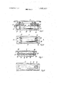
- FIG. 1 is a perspective overall view of a motor chain saw according to the invention.
- FIG. 2 shows in a simplified manner thebasic principle of a compensator used in connection with the present invention.
- FIG. 3 represents an axial longitudinal section through a first embodiment of a compensator according to the invention arranged in the handle frame of a motor chain saw according to the invention.
- FIG. 4 shows a compensator for the handle pipe of the motor chain saw according to FIG. 1.
- FIG. 5 illustrates a particularly favorable embodiment of a compensator according to the invention in combination with a connecting device for the handle system of a motor chain saw according to FIG. '1.
- FIG. 6 represents still another embodiment of a compensator according to'the invention which is tobe mounted in the handle of a motor chain saw according to FIG. 1 and is provided with preloaded supporting elements of rubber material.
- FIG. 7 shows a further compensator arrangement with a supporting member in the form of a spring bar.
- FIG. 8 shows a compensator arrangement, likewise intended for the handle, according to which the compensator mass is embedded on all sides in foam material so as to be able to carry out vibrations.
- FIG. 9 is a longitudinal section through still another compensator for use in a pipe of a handle system.
- FIG. 10 represents a longitudinal section through a compensator modified over that of FIG. 9.
- the portable implement, especially motor chain saw, according to the invention is characterized primarilyin that the handle of the implement is through the intervention of a spring-elastic connecting element connected to the implement, and is furthermore characterized in that at least one compensator comprising a compensator mass and at least one spring-elastic supporting member is connected to the handle and is adapted to vibrate relative thereto.
- the fundamental feature of such compensator arrangement consists in that the compensator mass is relative to the mass of the implement, which causes the oscillations and vibrations,'offset in counter phase oscillations and that the handle which is elastically coupled to the mass of the implement as well as to the mass of the compensator is located, at least, approximately in the vibration node or nodal point and therefore receives only slight amplitudes of movement.
- the supporting element is coaxial to a centrodial axis of the compensator mass.
- rubber material is employed for the spring-elastic connecting means for the handle and/or for the spring-elastic supporting element for the compensator mass.
- the compensator covers a wide range of frequency.
- the compensator mass and the supporting element or elements therefor form two approxi' mately symmetrical sections the resonance frequencies of which differ from each other'by from 10 to 25 percent.
- the compensator masses and their supporting elements effective relative to the handle are respectively tuned for resonance frequencies which differ from each other at least by 5 percent, preferably more than 10 percent.
- the main handle together with the other auxiliary handle may be combined to a rigid handle system.
- the handle system as a unit is through, at least, three spring-elastic connecting means connected to the implement. With such a connection it may be expedient to provide a compensator for each connecting area of the handle system.
- the supporting element or elements and for the spring-elastic connecting means of the handle or handle system may be expedient for the supporting element or elements and for the spring-elastic connecting means of the handle or handle system to provide a form and/or a clamping or connecting system which will yield a progressive spring characteristic.
- Such progressive spring characteristic brings about the advantage that with increasing vibration amplitudes the return forces increase considerably so that an overall likewise increasing resonance frequency is obtained.
- a progressive characteristic may also be realized by an air spring, for instance, in the form of a bellows. Such air springs yieldthe additional advantage that they are almost non-sensitive to temperatures.
- the compensator may advantageously be so arranged that its axis of symmetry is parallel to the crank-shaft.
- the compensator may advantageously be so arranged that its axis of symmetry is located in the handle frame in a direction transverse to the longitudinal axis of the handle frame.
- the compensator mass may follow each vibration impulse which is directed transverse to the axis of symmetry of the compensator mass and which is located primarily in the plane of the crank circle, while the rubber springs are subjected to shearing forces.
- a second compensator in the handle pipe and preferably coaxially in the handle pipe.
- the compensator mass in the form of a body of rotation, preferably in the form of a cylinder or cone. It is particularly advantageous in this connection to design the compensator mass so that it is symmetrical to a plane vertically intersecting the axis of rotation or the centroidal axis of the compensator mass.
- the motor chain saw illustrated in FIG. 1 comprises a housing 1 having mounted therein a not further illustrated onecylinder internal combustion engine which drives an endless saw chain 2 guided along the circumferential surface of a guiding rail 3.
- the crank-shaft of the internal combustion engine extends at a right angle with regard to the lateral surface (FIG. 1) of the guiding rail 3.
- a holding system which comprises a plurality of holding areas and primarily comprises a reawardly protruding handle 5 and a U-shaped bent handle pipe 7.
- the handle pipe 7 and the handle 5 are by means of a frame 8 combined to a handle system.
- This integrated holding system is through the intervention of rubber ring buffers 9, 17, 19 forming a spring-elastic connecting means supported with regard to housing 1.
- the not further illustrated rubber ring buffer 9 and the rubber ring buffer 17 are directly connected to the crank housing 18 of the internal combustion engine.
- the ring buffer pair 19 of which FIG. 1 shows only the buffer on the left-hand side of the handle is mounted on a cantilever arm 6.
- FIG. 2 the mass of the housing subjected by the crank drive of the internal combustion engine to vibrations or oscillations is designated with the reference numeral 10. Coupled to the housing 1 through a spring 11 actually formed by the ring buffers 9 is the mass 12 of the handle or handle system which is to be quieted.
- a compensator which compensator comprises a counter vibrating mass 13 and a spring 14 which acts as a spring-elastic supporting member.
- the mass 13 and the spring 14 are so tuned relative to each other that the two outer masses l0 and 13 respectively simultaneously move toward the handle mass 12 and subsequently away therefrom as indicated in the drawing by dash lines.
- the bandle mass 12 located between the two springs 11 and 14 remains approximately at rest inasmuch as in this celllating system it is located in the nodal points.
- the holding system 5, 7 and 8 as described above is combined and through three different supporting points 9, 17 and 19 is elastically supported by the implement housing.
- one compensator each may be provided.
- Each of these compensators consits of a compensator mass of the type symbolically indicated at 13 in FIG. 2 and of a spring-elastic supporting element indicated by the spring 14. More specifically, the compensators may be designed in conformity with the embodiments illustrated in FIGS. 3 to 8.
- the compensator according to FIG. 3 is intended for installation in the handle frame 8 illustrated in cross section and located in the immediate vicinity of the rubber buffer 9.
- the compensator of FIG. 3 comprises compensator masses 21, 24 and 25 which similar to the compensator mass of the remaining compensators of FIGS. 48 are designed in the form of bodies of rotation.
- the compensator is furthermore designed so as to form an image in a direction transverse to the axis A-A and on each of its two end studs or trunnions 22 and 23 is provided with a cap 24 and 25 respectively of steel.
- two conical ring buffers 26 and 27 the rubber bodies of which are at their end faces, respectively, connected to a metal sheet flange 28 and 29 by vulcanization.
- the inner metal flanges 29 rest against a longitudinal rib or an eye 30 of the handle frame 8.
- the rubber bodies of the conical ring buffers 26 and 27 may in the axial direction A-A be preloaded by the two caps 24 and 25 in such a way that a progressive spring characteristic of the rubber body is obtained.
- the oscillations of the compensator masses 21, 24, 25 may be effected in a direction transverse to the longitudinal axis AA and may compensate the mass forces caused in the plane of the crank circle.
- the compensator shown in FIG. 4 is provided primarily for quieting the handle pipe 7 of which a short section only is shown.
- the mass body 31 of the compensator has its faces respectively provided with short extensions 32, 33 respectively acted upon by two frustrated cone-shaped rubber buffers 34 and 35 acting as spring-elastic supporting elements. These buffers 34 and 35 are preloaded in axial direction. To this end,
- one face of the compensator is provided with a holding ring 37 held in its position by a depression or bead 36 and is furthermore provided with a pressed-in sleeve 38 which at the connecting area of the handle pipe 7 with the handle frame 8 is pressed into the handle pipe.
- FIG. 5 represents a particularly favorable arrangement according to which the compensator is combined with a connecting device for the handle system on the motor housing.
- the motor housing 40 of which only a small portion is shown is provided with two supporting arms 41 and 42, respectively cast onto opposite sides of the housing 40.
- Two metallic oscillating bodies 44 are respectively connected to the arms 41 and 42 by means of a screw while between the bodies 44 there are arranged compensator masses 46 which similar to those of FIG. 4 are of a cylindrical design and are provided with two extensions 45 at the end faces thereof.
- Each of the two bodies 44 has its outer end face vulcanized to a connecting flange 43 and in its rubber body 47 which extends all the way through contains a sheet metal fitting which extends all the way through contains a sheet metal fitting 48 which is vulcanized into the rubber body 47 and to which at 8 there is connected a handle frame shown in cross section.
- This connection is effected by means of screws 49.
- that part of the rubber body which acts as spring-elastic connecting member and which is located between the connecting plates 48 and the supporting arms 41 and 42 represents an extension of that part acting as supporting which is located between these connecting rings 48 and the compensator mass 46.
- FIG. 6 illustrates a modified embodiment of a compensator according to theinvention which is particularly well suited for mounting in the handle 5 of the motor chain saw.
- the likewise cylindrical compensator mass 51 is provided between two hollow truncated cone-shaped ring buffers 52 and 53 of rubber which rest against the annular shoulders 54 and 55 on the inner wall of the handle and thus are elastically preloaded in axial as well as in radial direction.
- a progressive spring characteristic is obtained whichmakes it possible to have oscillations not only in' the direction of the centroidal axis A-A of the compensator mass 51 but also transverse to this axis so that also rotary oscillations can be compensated for.
- the supporting member for the compensator mass 61 of the embodiment of FIG. 7 is represented by a spring bar 62 of steel.
- This bar 62 is fixedly located under preload in the central portion 63 of a central longitudinal bore 64.
- the portion 63 likewise yields a progressive spring characteristic when the compensator mass carries out torsion or rotary oscillations with degrees of freedom extending perpendicularly with regard to the axis of the bar 62.
- the end sections of the spring bar 62 which protrude from the compensator mass 61 are received in the eyes 65 of two ribs 66 protruding from the inner side of the handle frame 8 and are fastened by embossed noses 67.
- the compensator of FIG. 8 in addition to having the above mentioned functional advantages, furnishes the possibility of a particularly simple production because in this instance the compensator mass 71 formed as a simple round iron member is on all sides embedded in a foamed synthetic mass 72. This mass can easily be inserted at the handle area to be quieted into the there provided hollow chamber when the bar 71 is held in its respective positions by means of a holding mandrel inserted into a bore 73 in the end face of the bar 71, the holding mandrel not being shown in the drawing.
- the foamed mass of synthetic material advantageously consists of polyurethane which can be foamed on the spot by customary foaming methods with the addition of gas developing substances.
- the foamed mass of synthetic material may be entered into the handle area to be quieted in not yet hardened condition.
- the compensator mass is arranged in the slightly curved and slightly conical handle 5 of the motor chain saw. It is, or course, also possible to provide such compensator in other handle areas, for instance, in the handle pipe 7 and preferably in the vicinity of the yoke ends which serve as connecting areas and are located at the ring buffers 17 or in the vicinity of the handle frame 8.
- the compensator arrangements in FIGS. 9 and 10 are primarily intended for use on a pipe of the handle system and have the advantage that harmonic vibrations of the system, which system is to a major extent compensated in the remaining region, can be suppressed in which instance it is frequently necessary to ascertain that location which in practical operation is the most favorable for a maximum efficiency of the compensator mass.
- Ring 81 acts as compensating mass.
- the location of its maximum efficiency can be ascertained by displacement of the rubber ring 84 on the handle pipe 7 of the handle system. Expediently, this location is fixed, for instance, by means of an adhesive.
- the outwardly located steel ring 91 extends at both end faces of the rubber ring 94 around the latter with annular end sections 92 and 93, the rubber ring 94 serving as supporting member.
- These end sections 92 and 93 assure, on one hand, a safe connection of the steel ring 91 on the rubber ring 94 and, on the other hand, increase the mass of the steel ring.
- the end sections 92 and 93 are located opposite the circumferential surface of a handle pipe 7 with an annular gap 96 which permits the steel ring 91 to perform a sufficient compensating oscillating movement in radial direction.
- a portable tool comprising handle means having a mass inertia that is low relative to the mass of the tool, which includes: spring elastic connecting means, said handle means being connected to said tool through the intervention of said spring elastic connecting means, and compensator means comprising a compensator mass and spring elastic supporting means and being connected to said handle means so as to be oscillatable relative thereto, the handle means including a handle frame, and in which said compensator means is so arranged in said handle frame that the longitudinal axis of said compensator means extends in a direction transverse to the longitudinal axis of said handle frame, said handle frame including a handle pipe, said compensator means being arranged within said handle pipe.
- a portable tool according to claim 1 in which said supporting means are coaxially arranged with regard to an axis of said compensator mass.
- a portable tool in which said compensator mass and said spring elastic supporting means form two nearly symmetrical halves respectively having resonance frequencies differing from each other by from 10 to 25 percent.
- a portable tool according to claim 1, in which said compensator means include a plurality of compensator masses.
- a portable tool in which the spring elastic supporting means effective relative to said handle means are respectively arranged at places with a low vibration amplitude, whereas the compensator mass is arranged in spaced relationship to said last mentioned places.
- a portable tool in which the handle means include a plurality of handle areas, and in which said compensator means include a plurality of compensators, each area at which said handle means are connected to the tool by said spring elastic connecting means having a compensator associated therewith.
- a portable tool in which said spring elastic supporting means is so connected to said handle means as to yield a spring characteristic of varying character.
- a portable tool which includes a drive motor having a crank shaft, and in which said compensator means includes a plurality of compensators, at least one of said compensators having its longitudinal axis extending in a direction transverse to the axis of said crank shaft and has degrees of freedom of oscillation transverse to said crank shaft axis.
- a portable tool in which at least one compensator has its longitudinal axis substantially parallel to the axis of rotation of said crank shaft.
- a portable tool in which the handle means include a handle frame, and in which said compensator means is so arranged in said handle frame that the longitudinal axis of said compensator means extends in a direction transverse to the longitudinal axis of said handle frame.
- a portable tool in which the com ensator mass of said compensator means has the con rguration of a body of revolution.
- said spring elastic supporting means include rubber buffers, each of the two end faces of said compensator mass having arranged thereon a rubber buffer.
- said spring elastic supporting means for the compensator mass includes a s ring bar.
- a portable tool according to claim 1 which includes a mass of foamed synthetic material having the compensator mass embedded therein.
- a portable tool comprising handle means having a mass inertia that is low relative to the mass of the tool, which includes: spring elastic connecting means, said handle means being connected to said tool through the intervention of said spring elastic connecting means, and compensator means comprising a com ensator mass and spring elastic supporting means an being connected to said handle means so as to be oscillatable relative thereto, said spring elastic supporting means including rubber buffers, each of the two end faces of said compensator mass having arranged thereon a rubber buffer, the rubber buffer having that end face thereof which faces away from the compensator mass provided with a recess which with regard to the common axis is rotationsymmetric with said compensator mass.
- a portable tool especially motor chain saw, comprising handle means having a mass inertia that is low relative to the mass of the tool, which includes: spring elastic connecting means, said handle means being connected to said tool through the intervention of said spring elastic connecting means, and compensator means comprising a com ensator mass and spring elastic supporting means an bein connected to said handle means so as to be oscillata le relative thereto, said spring elastic supporting means for the compensator mass including a spring bar, said compensator mass having an axial bore, said spring bar being arranged in said axial bore.
Landscapes
- Engineering & Computer Science (AREA)
- Life Sciences & Earth Sciences (AREA)
- Mechanical Engineering (AREA)
- General Engineering & Computer Science (AREA)
- Wood Science & Technology (AREA)
- Forests & Forestry (AREA)
- Sawing (AREA)
Abstract
A portable tool, especially motor chain saw, which has its handle means through the intervention of spring elastic connecting means connected to the tool, and in which the handle means has at least one compensator connected thereto in such a way that the latter is adapted to oscillate relative to the handle means, the compensator comprising a compensator mass and at least one spring elastic supporting member.
Description
Ilruted States Patent 11 1 1111 3,845,827
Schulin 1 Nov. 5, 1974 [54] PORTABLE IMPLEMENT, ESPECIALLY 3,620,269 11/1971 Lange 173/162 X O O CHAIN SAW 3,728,793 4/1973 Makinson et a1. 173/162 X [75] Inventor: Gotthilf Schulin, Fellbach, Germany FOREIGN PATENTS OR APPLICATIONS 3 Assigneez Andreas Stihl Maschinenfabrik, 920,586 9/1960 Great Britain 188/1 B Neustadt, Germany Primary Examiner-Frank L. Abbott [22] Flled' 1972 Assistant Examiner-William F. Pate, Ill [21] Appl. No; 277,339 Attorney, Agent, or Firm-Walter Becker [52] US. Cl. 173/162, 16/116 R, 267/137 [57] ABSTRACT [51] Int. Cl B27b 17/00 A portable tool, especially motor chain saw, Wl'llCl'l has [58] Fleld of Search gb/ f/ d its handle means through the intervention of spring elastic connecting means connected to the tool, and in [56] R f d which the handle means has at least one compensator e erences connected thereto in such a way that the latter is UNITED STATES PATENTS adapted to oscillate relative to the handle means, the 2,875,731 3/1959 Settles et al. 173/162 X compensator comprising a compensator mass and at 3,275,089 9/1966 Kaiser et al 173/162 lea t one ring elastic supporting member. 3,486,585 12/1969 Richter et al... 188/266 X 1 3,525,373 8/1970 Kobayasi 173/162 26 Claims, 10 Drawing Figures PORTABLE IMPLEMENT, ESPECIALLY MOTOR CHAIN SAW The present invention relates to a portable implement, especially motor chain saw, which has, at least, one handle which is connected spring-elastically to the implement and has a low mass inertia with regard to its drive motor.
In particular with manual tools which, as is usually the case with motor chain saws, are driven by an internal combustion engine, frequently in view of the nonuniformity of the drive and in view of mass forces, vibrations occur which through the handle are conveyed to the operator and thereby make it more difficult to precisely guide the manual tool while simultaneously frquently also causing vibrations in the hands and the body of the operator which may be harmful to his health and may be the cause of disturbances in the blood circulation.
It is, therefore, an object of the present invention to provide means in connection with implements and manually operated tools of the type involved which will overcome the above outlined drawbacks.
This object and other objects and advantages of the invention will appear more clearly from the following speicification in connection with accompanying drawings, in which:
FIG. 1 is a perspective overall view of a motor chain saw according to the invention.
FIG. 2 shows in a simplified manner thebasic principle of a compensator used in connection with the present invention.
FIG. 3 represents an axial longitudinal section through a first embodiment of a compensator according to the invention arranged in the handle frame of a motor chain saw according to the invention.
FIG. 4 shows a compensator for the handle pipe of the motor chain saw according to FIG. 1.
FIG. 5 illustrates a particularly favorable embodiment of a compensator according to the invention in combination with a connecting device for the handle system of a motor chain saw according to FIG. '1.
FIG. 6 represents still another embodiment of a compensator according to'the invention which is tobe mounted in the handle of a motor chain saw according to FIG. 1 and is provided with preloaded supporting elements of rubber material.
FIG. 7 shows a further compensator arrangement with a supporting member in the form of a spring bar.
FIG. 8 shows a compensator arrangement, likewise intended for the handle, according to which the compensator mass is embedded on all sides in foam material so as to be able to carry out vibrations. FIG. 9 is a longitudinal section through still another compensator for use in a pipe of a handle system.
FIG. 10 represents a longitudinal section through a compensator modified over that of FIG. 9.
The portable implement, especially motor chain saw, according to the invention is characterized primarilyin that the handle of the implement is through the intervention of a spring-elastic connecting element connected to the implement, and is furthermore characterized in that at least one compensator comprising a compensator mass and at least one spring-elastic supporting member is connected to the handle and is adapted to vibrate relative thereto.
The fundamental feature of such compensator arrangement consists in that the compensator mass is relative to the mass of the implement, which causes the oscillations and vibrations,'offset in counter phase oscillations and that the handle which is elastically coupled to the mass of the implement as well as to the mass of the compensator is located, at least, approximately in the vibration node or nodal point and therefore receives only slight amplitudes of movement. In this connection it is of particular advantage when the supporting element is coaxial to a centrodial axis of the compensator mass. Although rubber will with decreasing temperatures lose considerably in elasticity with an increase in the vibration frequencies, it is expedient that according to a further feature of the invention rubber material is employed for the spring-elastic connecting means for the handle and/or for the spring-elastic supporting element for the compensator mass.
Inasmuch as the vibrations of the implement which originate with the drive motor depend on the speed of the drive motor which speed, however, decreases with increasing load, it is advantageous when the compensator covers a wide range of frequency. To this end, according to a further development of the invention, it is suggested that the compensator mass and the supporting element or elements therefor form two approxi' mately symmetrical sections the resonance frequencies of which differ from each other'by from 10 to 25 percent. A still better result, while covering a wide range of frequencies, is obtained when a plurality of compensators are employed. In this connection it is advantageous when the compensator masses and their supporting elements effective relative to the handle are respectively tuned for resonance frequencies which differ from each other at least by 5 percent, preferably more than 10 percent.
Not only with motor chain saws for which, in conformity with the present invention, one or more compensators are primarily employed, but also with a number of other portable motor-driven implements and manually operable tools as, for instance, free cutting machines, separating grinders, manual circular saws, etc., itis customary in addition to the handle proper to provide other handles or handle areas which will permit the operator to hold the tool or implement in its most favorable working position. With such arrangements, the main handle together with the other auxiliary handle may be combined to a rigid handle system. For such handle system it is suggested according to a further development of the invention that the handle system as a unit is through, at least, three spring-elastic connecting means connected to the implement. With such a connection it may be expedient to provide a compensator for each connecting area of the handle system.
Independently of the respective structural design of the compensator mass or masses it may be expedient for the supporting element or elements and for the spring-elastic connecting means of the handle or handle system to provide a form and/or a clamping or connecting system which will yield a progressive spring characteristic. Such progressive spring characteristic brings about the advantage that with increasing vibration amplitudes the return forces increase considerably so that an overall likewise increasing resonance frequency is obtained. A progressive characteristic may also be realized by an air spring, for instance, in the form of a bellows. Such air springs yieldthe additional advantage that they are almost non-sensitive to temperatures.
With a manually operated implement equipped with a drive motor in the form of an internal combustion engine and including a crank-shaft, the compensator may advantageously be so arranged that its axis of symmetry is parallel to the crank-shaft. When the implement and its above mentioned rigid handle system includes a handle frame to which the handle and/or a handle pipe arranged transverse to the longitudinal axis of the handle frame is connected, the compensator may advantageously be so arranged that its axis of symmetry is located in the handle frame in a direction transverse to the longitudinal axis of the handle frame. In such an instance the compensator mass may follow each vibration impulse which is directed transverse to the axis of symmetry of the compensator mass and which is located primarily in the plane of the crank circle, while the rubber springs are subjected to shearing forces. In addition thereto it is expedient to arrange a second compensator in the handle pipe and preferably coaxially in the handle pipe. For preparing as well as for mounting and for the operation of the compensator it is advantageous to design the compensator mass, according to a further developement of the invention, in the form of a body of rotation, preferably in the form of a cylinder or cone. It is particularly advantageous in this connection to design the compensator mass so that it is symmetrical to a plane vertically intersecting the axis of rotation or the centroidal axis of the compensator mass.
Referring now to the drawings in detail, the motor chain saw illustrated in FIG. 1 comprises a housing 1 having mounted therein a not further illustrated onecylinder internal combustion engine which drives an endless saw chain 2 guided along the circumferential surface of a guiding rail 3. The crank-shaft of the internal combustion engine extends at a right angle with regard to the lateral surface (FIG. 1) of the guiding rail 3. In order to assure that the implement may easily be moved into various conditions of operation required in practice and to permit an easy holding of the implement in these positions, there is provided a holding system which comprises a plurality of holding areas and primarily comprises a reawardly protruding handle 5 and a U-shaped bent handle pipe 7. The handle pipe 7 and the handle 5 are by means of a frame 8 combined to a handle system. This integrated holding system is through the intervention of rubber ring buffers 9, 17, 19 forming a spring-elastic connecting means supported with regard to housing 1. The not further illustrated rubber ring buffer 9 and the rubber ring buffer 17 are directly connected to the crank housing 18 of the internal combustion engine. The ring buffer pair 19 of which FIG. 1 shows only the buffer on the left-hand side of the handle is mounted on a cantilever arm 6.
During the operation of the motor chain saw, vibrations may occur in conformity with the respective speed of the drive motor. These vibrations make it more difficult for the operator to precisely guide the motor chain saw and they may be conveyed to the operator thereby affecting his working output. For reducing the vibrations of the handle, a plurality of compensator arrangements to be described further below are provided. The principle of the operation of such compensator arrangements is diagrammatically illustrated in FIG. 2. In FIG. 2 the mass of the housing subjected by the crank drive of the internal combustion engine to vibrations or oscillations is designated with the reference numeral 10. Coupled to the housing 1 through a spring 11 actually formed by the ring buffers 9 is the mass 12 of the handle or handle system which is to be quieted. This arrangement is supplemented to form a symmetrical system. To this end, that end of the handle mass 12 which faces away from the implement mass 10 is equipped with a compensator according to the invention which compensator comprises a counter vibrating mass 13 and a spring 14 which acts as a spring-elastic supporting member. The mass 13 and the spring 14 are so tuned relative to each other that the two outer masses l0 and 13 respectively simultaneously move toward the handle mass 12 and subsequently away therefrom as indicated in the drawing by dash lines. The bandle mass 12 located between the two springs 11 and 14 remains approximately at rest inasmuch as in this celllating system it is located in the nodal points.
In order to assure that the holding system with a practical realization of the just described compensator principle will be able to act as a rigid unit with as large a mass as possible, the holding system 5, 7 and 8 as described above is combined and through three different supporting points 9, 17 and 19 is elastically supported by the implement housing. In the vicinity of each of these supporting points, one compensator each may be provided. Each of these compensators consits of a compensator mass of the type symbolically indicated at 13 in FIG. 2 and of a spring-elastic supporting element indicated by the spring 14. More specifically, the compensators may be designed in conformity with the embodiments illustrated in FIGS. 3 to 8.
The compensator according to FIG. 3 is intended for installation in the handle frame 8 illustrated in cross section and located in the immediate vicinity of the rubber buffer 9. The compensator of FIG. 3 comprises compensator masses 21, 24 and 25 which similar to the compensator mass of the remaining compensators of FIGS. 48 are designed in the form of bodies of rotation. The compensator is furthermore designed so as to form an image in a direction transverse to the axis A-A and on each of its two end studs or trunnions 22 and 23 is provided with a cap 24 and 25 respectively of steel. Between the two caps and likewise in symmetrical arrangement there are provided two conical ring buffers 26 and 27 the rubber bodies of which are at their end faces, respectively, connected to a metal sheet flange 28 and 29 by vulcanization. The inner metal flanges 29 rest against a longitudinal rib or an eye 30 of the handle frame 8. The rubber bodies of the conical ring buffers 26 and 27 may in the axial direction A-A be preloaded by the two caps 24 and 25 in such a way that a progressive spring characteristic of the rubber body is obtained. The oscillations of the compensator masses 21, 24, 25 may be effected in a direction transverse to the longitudinal axis AA and may compensate the mass forces caused in the plane of the crank circle.
The compensator shown in FIG. 4 is provided primarily for quieting the handle pipe 7 of which a short section only is shown. The mass body 31 of the compensator has its faces respectively provided with short extensions 32, 33 respectively acted upon by two frustrated cone-shaped rubber buffers 34 and 35 acting as spring-elastic supporting elements. These buffers 34 and 35 are preloaded in axial direction. To this end,
one face of the compensator is provided with a holding ring 37 held in its position by a depression or bead 36 and is furthermore provided with a pressed-in sleeve 38 which at the connecting area of the handle pipe 7 with the handle frame 8 is pressed into the handle pipe.
The embodiment illustrated in FIG. 5 represents a particularly favorable arrangement according to which the compensator is combined with a connecting device for the handle system on the motor housing. The motor housing 40 of which only a small portion is shown is provided with two supporting arms 41 and 42, respectively cast onto opposite sides of the housing 40. Two metallic oscillating bodies 44 are respectively connected to the arms 41 and 42 by means of a screw while between the bodies 44 there are arranged compensator masses 46 which similar to those of FIG. 4 are of a cylindrical design and are provided with two extensions 45 at the end faces thereof. Each of the two bodies 44 has its outer end face vulcanized to a connecting flange 43 and in its rubber body 47 which extends all the way through contains a sheet metal fitting which extends all the way through contains a sheet metal fitting 48 which is vulcanized into the rubber body 47 and to which at 8 there is connected a handle frame shown in cross section. This connection is effected by means of screws 49. For the suprisingly good effect of this compensator it has proved particularly advantageous that that part of the rubber body which acts as spring-elastic connecting member and which is located between the connecting plates 48 and the supporting arms 41 and 42 represents an extension of that part acting as supporting which is located between these connecting rings 48 and the compensator mass 46.
FIG. 6 illustrates a modified embodiment of a compensator according to theinvention which is particularly well suited for mounting in the handle 5 of the motor chain saw. The likewise cylindrical compensator mass 51 is provided between two hollow truncated cone-shaped ring buffers 52 and 53 of rubber which rest against the annular shoulders 54 and 55 on the inner wall of the handle and thus are elastically preloaded in axial as well as in radial direction. In .view of this preload, a progressive spring characteristic is obtained whichmakes it possible to have oscillations not only in' the direction of the centroidal axis A-A of the compensator mass 51 but also transverse to this axis so that also rotary oscillations can be compensated for.
Whereas with the so far described embodiments of the invention the supporting members pertaining to the compensator are made of rubber, the supporting member for the compensator mass 61 of the embodiment of FIG. 7 is represented by a spring bar 62 of steel. This bar 62 is fixedly located under preload in the central portion 63 of a central longitudinal bore 64. The portion 63 likewise yields a progressive spring characteristic when the compensator mass carries out torsion or rotary oscillations with degrees of freedom extending perpendicularly with regard to the axis of the bar 62.
The end sections of the spring bar 62 which protrude from the compensator mass 61 are received in the eyes 65 of two ribs 66 protruding from the inner side of the handle frame 8 and are fastened by embossed noses 67.
The compensator of FIG. 8, in addition to having the above mentioned functional advantages, furnishes the possibility of a particularly simple production because in this instance the compensator mass 71 formed as a simple round iron member is on all sides embedded in a foamed synthetic mass 72. This mass can easily be inserted at the handle area to be quieted into the there provided hollow chamber when the bar 71 is held in its respective positions by means of a holding mandrel inserted into a bore 73 in the end face of the bar 71, the holding mandrel not being shown in the drawing. The foamed mass of synthetic material advantageously consists of polyurethane which can be foamed on the spot by customary foaming methods with the addition of gas developing substances. However, if desired, the foamed mass of synthetic material may be entered into the handle area to be quieted in not yet hardened condition. With the illustrated embodiment it is provided that the compensator mass is arranged in the slightly curved and slightly conical handle 5 of the motor chain saw. It is, or course, also possible to provide such compensator in other handle areas, for instance, in the handle pipe 7 and preferably in the vicinity of the yoke ends which serve as connecting areas and are located at the ring buffers 17 or in the vicinity of the handle frame 8.
The compensator arrangements in FIGS. 9 and 10 are primarily intended for use on a pipe of the handle system and have the advantage that harmonic vibrations of the system, which system is to a major extent compensated in the remaining region, can be suppressed in which instance it is frequently necessary to ascertain that location which in practical operation is the most favorable for a maximum efficiency of the compensator mass.
The compensator arrangement according to FIG. 9
has a rubber ring 84 which forms the elastic supporting member and which is firmly connected at its circumferential surface by vulcanizing to a steel ring 81. Ring 81 acts as compensating mass. The location of its maximum efficiency can be ascertained by displacement of the rubber ring 84 on the handle pipe 7 of the handle system. Expediently, this location is fixed, for instance, by means of an adhesive.
, With the modified compensator of FIG. 10, the outwardly located steel ring 91 extends at both end faces of the rubber ring 94 around the latter with annular end sections 92 and 93, the rubber ring 94 serving as supporting member. These end sections 92 and 93 assure, on one hand, a safe connection of the steel ring 91 on the rubber ring 94 and, on the other hand, increase the mass of the steel ring. The end sections 92 and 93 are located opposite the circumferential surface of a handle pipe 7 with an annular gap 96 which permits the steel ring 91 to perform a sufficient compensating oscillating movement in radial direction.
When the supporting members of the compensator mass or masses are made of rubber or foam material,
it will be appreciated that in view of the shape changing work in these materials, a heat development will occur which above all at lower outer temperatures facilitates the handling of the implement because in view of this damping heat a slight heating up of the handle areas will result.
It is, of course, to be understood that the present invention is, by no means, limited to the specific embodiments shown in the drawings but also comprises any modifications within the scope of the appended claims.
What I claim is:
1. A portable tool, especially motor chain saw, comprising handle means having a mass inertia that is low relative to the mass of the tool, which includes: spring elastic connecting means, said handle means being connected to said tool through the intervention of said spring elastic connecting means, and compensator means comprising a compensator mass and spring elastic supporting means and being connected to said handle means so as to be oscillatable relative thereto, the handle means including a handle frame, and in which said compensator means is so arranged in said handle frame that the longitudinal axis of said compensator means extends in a direction transverse to the longitudinal axis of said handle frame, said handle frame including a handle pipe, said compensator means being arranged within said handle pipe.
2. A portable tool according to claim 1, in which said supporting means are coaxially arranged with regard to an axis of said compensator mass.
3. A portable tool according to claim 1, in which, at least, one of said spring elastic connecting means and said spring elastic supporting means is made of rubber material.
4. A portable tool according to claim 1, in which said compensator mass and said spring elastic supporting means form two nearly symmetrical halves respectively having resonance frequencies differing from each other by from 10 to 25 percent.
5. A portable tool according to claim 1, in which said compensator means include a plurality of compensator masses.
6. A portable tool according to claim 1, in which the spring elastic supporting means effective relative to said handle means are respectively arranged at places with a low vibration amplitude, whereas the compensator mass is arranged in spaced relationship to said last mentioned places.
7. A portable tool according to claim 1, in which the handle means include a plurality of handle areas, and in which said compensator means include a plurality of compensators, each area at which said handle means are connected to the tool by said spring elastic connecting means having a compensator associated therewith.
8. A portable tool according to claim 1, in which said spring elastic supporting means is so shaped as to yield a spring characteristic of varying character.
9. A portable tool according to claim 1, in which said spring elastic supporting means is so connected to said handle means as to yield a spring characteristic of varying character.
10. A portable tool according to claim 1, which includes a drive motor having a crank shaft, and in which said compensator means includes a plurality of compensators, at least one of said compensators having its longitudinal axis extending in a direction transverse to the axis of said crank shaft and has degrees of freedom of oscillation transverse to said crank shaft axis.
11. a portable tool according to claim 10, in which at least one compensator has its longitudinal axis substantially parallel to the axis of rotation of said crank shaft.
12. A portable tool according to claim 1, in which the handle means include a handle frame, and in which said compensator means is so arranged in said handle frame that the longitudinal axis of said compensator means extends in a direction transverse to the longitudinal axis of said handle frame.
13. A portable tool according to claim 1, in which said compensator means is coaxially arranged in said handle pipe.
14. A portable tool according to claim 1, in which the com ensator mass of said compensator means has the con rguration of a body of revolution.
15. A portable tool according to claim 14, in which the compensator mass is symmetrical with regard to a plane vertically intersecting one of the axes of said compensator mass.
16. A portable tool according to claim 1, in which said spring elastic supporting means include rubber buffers, each of the two end faces of said compensator mass having arranged thereon a rubber buffer.
17. A portable tool according to claim 1, in which said spring elastic supporting means for the compensator mass includes a s ring bar.
18. A portable tool according to claim 1, which includes a mass of foamed synthetic material having the compensator mass embedded therein.
19. A portable tool according to claim 1, in which the compensator mass is coaxially arranged in a handle ipe.
20. A portable tool, especially motor chain saw, comprising handle means having a mass inertia that is low relative to the mass of the tool, which includes: spring elastic connecting means, said handle means being connected to said tool through the intervention of said spring elastic connecting means, and compensator means comprising a com ensator mass and spring elastic supporting means an being connected to said handle means so as to be oscillatable relative thereto, said spring elastic supporting means including rubber buffers, each of the two end faces of said compensator mass having arranged thereon a rubber buffer, the rubber buffer having that end face thereof which faces away from the compensator mass provided with a recess which with regard to the common axis is rotationsymmetric with said compensator mass.
21. A portable tool according to claim 20, in which the rubber buffers respectively arranged on each of the two end faces of said compensator mass having the configuration of a body of rotation.
22. A portable tool accordin to claim 20, in which the rubber buffer is at that end ace thereof which faces away from said compensator mass clamped-in in radial direction.
23. A portable tool according to claim 20, inwhich the rubber buffer is at that end face thereof which faces away from said compensator mass clamped-in axially.
24. A portable tool according to claim 20, in which the compensator mass has its end faces respectively provided with extension means, rubber buffers respectively being mounted on said extension means.
25. A portable tool. especially motor chain saw, comprising handle means having a mass inertia that is low relative to the mass of the tool, which includes: spring elastic connecting means, said handle means being connected to said tool through the intervention of said spring elastic connecting means, and compensator means comprising a com ensator mass and spring elastic supporting means an bein connected to said handle means so as to be oscillata le relative thereto, said spring elastic supporting means for the compensator mass including a spring bar, said compensator mass having an axial bore, said spring bar being arranged in said axial bore.
26. A portable tool according to claim 25, in which said axial bore has its central portion provided with a crowned section sup por ting sa d spring bar.
UNITED STATES PATENT OFFICE @ERTIFICATE 0F CORRECTION Patent 3 Dated November 5 1974 Gotthilf Schulin Inventor(s) It is certified that error appears in the above-identified patent and that said Letters Patent are hereby corrected as shown below:
On the cover sheet insert;
[30] Foreign Application Priority Data August 5, 1971 Germany P 21 39 192.4
Signed and Evcaled this twenty-ninth Day Of July 1975 [SEAL] AIIESI.
RUTH C. MASON C. MARSHALL DANN AIH II'HK ()jfI'CP ('mmnixsimu'r uj'lurenls and Trademarks F ORM PO-105O (10-69) uscoMM-Dc 60376-1 69 U.S GOVERNMENT PRINTING OFFICE: 8 9, 930
Claims (26)
1. A protable tool, especially motor chain saw, comprising handle means having a mass inertia that is low relative to the mass of the tool, which includes: spring elastic connecting means, said handle means being connected to said tool through the intervention of said spring elastic connecting means, and compensator means comprising a compensator mass and spring elastic supporting means and being connected to said handle means so as to be oscillatable relative thereto, the handle means including a handle frame, and in which said compensator means is so arranged in said handle frame that the longitudinal axis of said compensator means extends in a direction transverse to the longitudinal axis of said handle frame, said handle frame including a handle pipe, said compensator means being arranged within said handle pipe.
2. A portable tool according to claim 1, in which said supporting means are coaxially arranged with regard to an axis of said compensator mass.
3. A portable tool according to claim 1, in which, at least, one of said spring elastic connecting means and said spring elastic supporting means is made of rubber material.
4. A portable tool according to claim 1, in which said compensator mass and said spring elastic supporting means form two nearly symmetrical halves respectively having resonance frequencies differing from each other by from 10 to 25 percent.
5. A portable tool according to claim 1, in which said compensator means include a plurality of compensator masses.
6. A portable tool according to claim 1, in which the spring elastic supporting means effective relative to said handle means are respectively arranged at places with a low vibration amplitude, whereas the compensator mass is arranged in spaced relationship to said last mentioned places.
7. A portable tool according to claim 1, in which the handle means include a plurality of handle areas, and in which said compensator means include a plurality of compensators, each area at which said handle means are connected to the tool by said spring elastic connecting means having a compensator associated therewith.
8. A portable tool according to claim 1, in which said spring elastic supporting means is so shaped as to yield a spring characteristic of varying character.
9. A portable tool according to claim 1, in which said spring elastic supporting means is so connected to said handle means as to yield a spring characteristic of varying character.
10. A portable tool according to claim 1, which includes a drive motor having a crank shaft, and in which said compensator means includes a plurality of compensators, at least one of said compensators having its longitudinal axis extending in a direction transverse to the axis of said crank shaft and has degrees of freedom of oscillation transverse to said crank shaft axis.
11. a portable tool according to claim 10, in which at least one compensator has its longitudinal axis substantially parallel to the axis of rotation of said crank shaft.
12. A portable tool according to claim 1, in which the handle means include a handle frame, and in which said compensator means is so arranged in said handle frame that the longitudinal axis of said compensator means extends in a direction transverse to the longitudinal axis of said handle frame.
13. A portable tool according to claim 1, in which said compensator means is coaxially arranged in said handle pipe.
14. A portable tool according to claim 1, in which the compensator mass of said compensator means has the configuration of a body of revolution.
15. A portable tool according to claim 14, in which the compensator mass is symmetrical with regard to a plane vertically intersecting one of the axes of said compensator mass.
16. A portable tool according to claim 1, in which said spring elastic supporting means include rubber buffers, each of the two end faces of said compensator mass having arranged thereon a rubber buffer.
17. A portable tool according to claim 1, in which said spring elastic supporting means for the compensator mass includes a spring bar.
18. A portable tool according to claim 1, which includes a mass of foamed synthetic material having the compensator mass embedded therein.
19. A portable tool according to claim 1, in which the compensator mass is coaxially arranged in a handle pipe.
20. A portable tool, especially motor chain saw, comprising handle means having a mass inertia that is low relative to the mass of the tool, which includes: spring elastic connecting means, said handle means being connected to said tool through the intervention of said spring elastic connecting means, and compensator means comprising a compensator mass and spring elastic supporting means and being connected to said handle means so as to be oscillatable relative thereto, said spring elastic supporting means including rubber buffers, each of the two end faces of said compensator mass having arranged thereon a rubber buffer, the rubber buffer having that end face thereof which faces away from the compensator mass provided with a recess which with regard to the common axis is rotation-symmetric with said compensator mass.
21. A portable tool according to claim 20, in which the rubber buffers respectively arranged on each of the two end faces of said compensator mass having the configuration of a body of rotation.
22. A portable tool according to claim 20, in which the rubber buffer is at that end face thereof which faces away from said compensator mass clamped-in in radial direction.
23. A portable tool according to claim 20, inwhich the rubber buffer is at that end face thereof which faces away from said compensator mass clamped-in axially.
24. A portable tool according to claim 20, in which the compensator mass has its end faces respectively provided with extension means, rubber buffers respectively being mounted on said extension means.
25. A portable tool, especially motor chain saw, comprising handle means having a mass inertia that is low relative to the mass of the tool, which includes: spring elastic connecting means, said handle means being connected to said tool through the intervention of said spring elastic connecting means, and compensator means comprising a compensator mass and spring elastic supporting means and being connected to said handle means so as to be oscillatable relative thereto, said spring elastic supporting means for the compensator mass including a spring bar, said compensator mass having an axial bore, said spring bar being arranged in said axial bore.
26. A portable tool according to claim 25, in which said axial bore has its central portion provided with a crowned section supporting said spring bar.
Priority Applications (1)
| Application Number | Priority Date | Filing Date | Title |
|---|---|---|---|
| US00277339A US3845827A (en) | 1971-08-05 | 1972-08-02 | Portable implement,especially motor chain saw |
Applications Claiming Priority (2)
| Application Number | Priority Date | Filing Date | Title |
|---|---|---|---|
| DE19712139192 DE2139192A1 (en) | 1971-08-05 | 1971-08-05 | PORTABLE MACHINE TOOL, ESPECIALLY POWER CHAIN SAW |
| US00277339A US3845827A (en) | 1971-08-05 | 1972-08-02 | Portable implement,especially motor chain saw |
Publications (1)
| Publication Number | Publication Date |
|---|---|
| US3845827A true US3845827A (en) | 1974-11-05 |
Family
ID=25761545
Family Applications (1)
| Application Number | Title | Priority Date | Filing Date |
|---|---|---|---|
| US00277339A Expired - Lifetime US3845827A (en) | 1971-08-05 | 1972-08-02 | Portable implement,especially motor chain saw |
Country Status (1)
| Country | Link |
|---|---|
| US (1) | US3845827A (en) |
Cited By (46)
| Publication number | Priority date | Publication date | Assignee | Title |
|---|---|---|---|---|
| US3945119A (en) * | 1975-01-28 | 1976-03-23 | Kioritz Corporation | Vibration isolation device for handles of chain saw |
| US3972119A (en) * | 1975-08-25 | 1976-08-03 | Mcculloch Corporation | Chain saw with a bifurcated diaphragm means providing a coaxial vibration-isolating unit |
| US4282938A (en) * | 1978-03-25 | 1981-08-11 | Yokosuka Boat Kabushiki Kaisha | Vibration insulation device for handle of vibratory machine |
| US4364293A (en) * | 1979-06-09 | 1982-12-21 | E. C. H. Will (Gmbh & Co.) | Rotary knife holder with means for damping its natural frequency oscillations |
| US4365770A (en) * | 1978-08-04 | 1982-12-28 | United Technologies Corp. | Fixed position variable frequency pendular-type vibration absorber |
| US4550812A (en) * | 1978-08-04 | 1985-11-05 | United Technologies Corporation | Fixed position, fixed frequency pendular-type vibration absorber with frequency linearization |
| US4558852A (en) * | 1982-03-11 | 1985-12-17 | Sig Schweizerische Industrie-Gesellschaft | Vibration damper with linearly reciprocating mass |
| US4670985A (en) * | 1984-12-17 | 1987-06-09 | Mcculloch Corporation | Vibration mount in a chainsaw |
| US5016355A (en) * | 1990-06-25 | 1991-05-21 | Textron Inc. | Vibration reducing chain saw handle |
| US5361500A (en) * | 1992-07-17 | 1994-11-08 | Aktiebolaget Electrolux | De-vibration element |
| US5445365A (en) * | 1993-03-18 | 1995-08-29 | Firma Andreas Stihl | Anti-vibration element |
| WO1996009907A1 (en) * | 1994-09-29 | 1996-04-04 | Rti Technologies, Inc. | On-car disc brake lathe |
| US5665019A (en) * | 1996-02-05 | 1997-09-09 | Ford Global Technologies, Inc. | Chain guide mounting assembly for the reduction of chain induced noise and vibration in a chain driven overhead cam internal combustion engine |
| US5766720A (en) * | 1993-10-05 | 1998-06-16 | Toray Industries, Inc. | Impact vibration absorbers and devices that incorporated them |
| US5846629A (en) * | 1996-05-31 | 1998-12-08 | Lord Corporation | Cushioning handle wrap for isolating vibration |
| US6026910A (en) * | 1998-01-13 | 2000-02-22 | Chicago Pneumatic Tool Company | Power tool and vibration isolator therefor |
| US6032558A (en) * | 1998-03-20 | 2000-03-07 | Marquip, Inc. | Rotary knife with active vibration control |
| US6389941B1 (en) | 2000-04-14 | 2002-05-21 | Marquip, Llc | Rotary knife with electromagnetic active vibration control |
| US6508343B2 (en) * | 2000-01-18 | 2003-01-21 | Honda Giken Kogyo Kabushiki Kaisha | Vibration damper |
| US20030132016A1 (en) * | 2001-04-11 | 2003-07-17 | Gerhard Meixner | Hand tool machine comprising a vibration-dampened handle |
| EP1614513A1 (en) * | 2004-07-05 | 2006-01-11 | Aktiebolaget Electrolux | A combustion engine powered portable, hand-held working machine |
| US20060289185A1 (en) * | 2005-06-23 | 2006-12-28 | Norbert Hahn | Vibration dampening mechanism |
| US20070017684A1 (en) * | 2003-03-21 | 2007-01-25 | Micheal Stirm | Vibration reduction apparatus for power tool and power tool incorporating such apparatus |
| US20070151404A1 (en) * | 2005-12-14 | 2007-07-05 | Yamaha Hatsudoki Kabushiki Kaisha | Vehicle Handle and Vehicle |
| US20070234578A1 (en) * | 2004-11-25 | 2007-10-11 | Johannes Menzel | Portable handheld work apparatus |
| US20070292208A1 (en) * | 2006-06-15 | 2007-12-20 | Wacker Corporation | Portable Vibratory Screed with Bubble Vial Inclination Indication System |
| US20080179797A1 (en) * | 2007-01-31 | 2008-07-31 | Hilti Aktiengesellschaft | Oscillation damper for a hand-held power tool |
| US20080185165A1 (en) * | 2007-01-31 | 2008-08-07 | Franz Moessnang | Hand-held power tool with an oscillation damper |
| US20090038899A1 (en) * | 2007-08-06 | 2009-02-12 | Roswitha Eicher | Auxiliary handle device |
| US20090223693A1 (en) * | 2004-08-27 | 2009-09-10 | Makita Corporation | Power tool |
| CN100563944C (en) * | 2004-07-07 | 2009-12-02 | 哈斯科瓦那股份公司 | A kind of oil-engine driven portable hand-held tool |
| USD607292S1 (en) * | 2007-04-27 | 2010-01-05 | Andreas Stihl Ag & Co. Kg | Chain saw |
| USD607293S1 (en) * | 2007-04-27 | 2010-01-05 | Andreas Stihl Ag & Co. Kg | Chain saw |
| US20100000751A1 (en) * | 2008-07-07 | 2010-01-07 | Makita Corporation | Power tool |
| US20100000752A1 (en) * | 2008-06-11 | 2010-01-07 | Black & Decker Inc. | Resilient Stop Assembly For Impact Tool |
| US20110100665A1 (en) * | 2008-04-04 | 2011-05-05 | Makita Corporation | Hand-held power tool |
| WO2011072916A1 (en) * | 2009-12-16 | 2011-06-23 | Robert Bosch Gmbh | Hand-power tool with an oscillation-damping device |
| US20120067605A1 (en) * | 2009-04-10 | 2012-03-22 | Makita Corporation | Striking tool |
| CN102666028A (en) * | 2009-12-16 | 2012-09-12 | 罗伯特·博世有限公司 | Handheld machine tool device |
| USD741678S1 (en) | 2012-04-13 | 2015-10-27 | Andreas Stihl Ag & Co. Kg | Chain saw for cutting stone |
| USD744308S1 (en) | 2012-08-02 | 2015-12-01 | Andreas Stihl Ag & Co. Kg | Chainsaw |
| USD763051S1 (en) | 2014-04-04 | 2016-08-09 | Andreas Stihl Ag & Co. Kg | Chainsaw |
| USD790303S1 (en) | 2015-08-06 | 2017-06-27 | Andreas Stihl Ag & Co. Kg | Cordless chainsaw |
| US20170361447A1 (en) * | 2014-12-03 | 2017-12-21 | Hilti Aktiengesellschaft | Control method for a hand-held power tool |
| USD826021S1 (en) | 2016-02-15 | 2018-08-21 | Andreas Stihl Ag & Co., Kg | Chain saw |
| US11571796B2 (en) * | 2018-04-04 | 2023-02-07 | Milwaukee Electric Tool Corporation | Rotary hammer |
-
1972
- 1972-08-02 US US00277339A patent/US3845827A/en not_active Expired - Lifetime
Cited By (81)
| Publication number | Priority date | Publication date | Assignee | Title |
|---|---|---|---|---|
| US3945119A (en) * | 1975-01-28 | 1976-03-23 | Kioritz Corporation | Vibration isolation device for handles of chain saw |
| US3972119A (en) * | 1975-08-25 | 1976-08-03 | Mcculloch Corporation | Chain saw with a bifurcated diaphragm means providing a coaxial vibration-isolating unit |
| US4282938A (en) * | 1978-03-25 | 1981-08-11 | Yokosuka Boat Kabushiki Kaisha | Vibration insulation device for handle of vibratory machine |
| US4365770A (en) * | 1978-08-04 | 1982-12-28 | United Technologies Corp. | Fixed position variable frequency pendular-type vibration absorber |
| US4550812A (en) * | 1978-08-04 | 1985-11-05 | United Technologies Corporation | Fixed position, fixed frequency pendular-type vibration absorber with frequency linearization |
| US4364293A (en) * | 1979-06-09 | 1982-12-21 | E. C. H. Will (Gmbh & Co.) | Rotary knife holder with means for damping its natural frequency oscillations |
| US4558852A (en) * | 1982-03-11 | 1985-12-17 | Sig Schweizerische Industrie-Gesellschaft | Vibration damper with linearly reciprocating mass |
| US4650167A (en) * | 1982-03-11 | 1987-03-17 | Sig Schweizerische Industrie-Gesellschaft | Vibration damper |
| US4670985A (en) * | 1984-12-17 | 1987-06-09 | Mcculloch Corporation | Vibration mount in a chainsaw |
| US5016355A (en) * | 1990-06-25 | 1991-05-21 | Textron Inc. | Vibration reducing chain saw handle |
| US5361500A (en) * | 1992-07-17 | 1994-11-08 | Aktiebolaget Electrolux | De-vibration element |
| US5445365A (en) * | 1993-03-18 | 1995-08-29 | Firma Andreas Stihl | Anti-vibration element |
| US5766720A (en) * | 1993-10-05 | 1998-06-16 | Toray Industries, Inc. | Impact vibration absorbers and devices that incorporated them |
| WO1996009907A1 (en) * | 1994-09-29 | 1996-04-04 | Rti Technologies, Inc. | On-car disc brake lathe |
| US5549023A (en) * | 1994-09-29 | 1996-08-27 | Rti Technologies, Inc. | On-car disc brake lathe |
| US5665019A (en) * | 1996-02-05 | 1997-09-09 | Ford Global Technologies, Inc. | Chain guide mounting assembly for the reduction of chain induced noise and vibration in a chain driven overhead cam internal combustion engine |
| US5846629A (en) * | 1996-05-31 | 1998-12-08 | Lord Corporation | Cushioning handle wrap for isolating vibration |
| US6026910A (en) * | 1998-01-13 | 2000-02-22 | Chicago Pneumatic Tool Company | Power tool and vibration isolator therefor |
| US6220367B1 (en) | 1998-01-13 | 2001-04-24 | Chicago Pneumatic Tool Company | Power tool and vibration isolator therefor |
| US6032558A (en) * | 1998-03-20 | 2000-03-07 | Marquip, Inc. | Rotary knife with active vibration control |
| US6508343B2 (en) * | 2000-01-18 | 2003-01-21 | Honda Giken Kogyo Kabushiki Kaisha | Vibration damper |
| US6389941B1 (en) | 2000-04-14 | 2002-05-21 | Marquip, Llc | Rotary knife with electromagnetic active vibration control |
| US20030132016A1 (en) * | 2001-04-11 | 2003-07-17 | Gerhard Meixner | Hand tool machine comprising a vibration-dampened handle |
| US7100706B2 (en) * | 2001-04-11 | 2006-09-05 | Robert Bosch Gmbh | Hand tool machine comprising a vibration-dampened handle |
| US7562721B2 (en) | 2003-03-21 | 2009-07-21 | Black & Decker Inc. | Vibration reduction apparatus for power tool and power tool incorporating such apparatus |
| US20080190634A1 (en) * | 2003-03-21 | 2008-08-14 | Black & Decker Inc. | Vehicle control system |
| US20070017684A1 (en) * | 2003-03-21 | 2007-01-25 | Micheal Stirm | Vibration reduction apparatus for power tool and power tool incorporating such apparatus |
| US7533736B2 (en) | 2003-03-21 | 2009-05-19 | Black & Decker Inc. | Vibration reduction apparatus for power tool and power tool incorporating such apparatus |
| US7331407B2 (en) | 2003-03-21 | 2008-02-19 | Black & Decker Inc. | Vibration reduction apparatus for power tool and power tool incorporating such apparatus |
| US20080099223A1 (en) * | 2003-03-21 | 2008-05-01 | Michael Stirm | Vibration reduction apparatus for power tool and power tool incorporating such apparatus |
| US7445056B2 (en) | 2003-03-21 | 2008-11-04 | Black & Decker Inc. | Vibration reduction apparatus for power tool and power tool incorporating such apparatus |
| US20080196915A1 (en) * | 2003-03-21 | 2008-08-21 | Black & Decker Inc. | Vehicle control system |
| EP1614513A1 (en) * | 2004-07-05 | 2006-01-11 | Aktiebolaget Electrolux | A combustion engine powered portable, hand-held working machine |
| CN100563944C (en) * | 2004-07-07 | 2009-12-02 | 哈斯科瓦那股份公司 | A kind of oil-engine driven portable hand-held tool |
| US8127862B2 (en) | 2004-08-27 | 2012-03-06 | Makita Corporation | Power tool |
| US20090223693A1 (en) * | 2004-08-27 | 2009-09-10 | Makita Corporation | Power tool |
| US8561716B2 (en) * | 2004-08-27 | 2013-10-22 | Makita Corporation | Power tool |
| US20100018735A1 (en) * | 2004-08-27 | 2010-01-28 | Makita Corporation | Power tool |
| US8235138B2 (en) | 2004-08-27 | 2012-08-07 | Makita Corporation | Power tool |
| US7921934B2 (en) * | 2004-08-27 | 2011-04-12 | Makita Corporation | Power tool |
| US20100252291A1 (en) * | 2004-08-27 | 2010-10-07 | Makita Corporation | Power tool |
| US20120261153A1 (en) * | 2004-08-27 | 2012-10-18 | Makita Coporation | Power tool |
| US20070234578A1 (en) * | 2004-11-25 | 2007-10-11 | Johannes Menzel | Portable handheld work apparatus |
| US20060289185A1 (en) * | 2005-06-23 | 2006-12-28 | Norbert Hahn | Vibration dampening mechanism |
| US7451833B2 (en) | 2005-06-23 | 2008-11-18 | Black & Decker Inc. | Vibration dampening mechanism |
| US20070151404A1 (en) * | 2005-12-14 | 2007-07-05 | Yamaha Hatsudoki Kabushiki Kaisha | Vehicle Handle and Vehicle |
| US8117942B2 (en) * | 2005-12-14 | 2012-02-21 | Yamaha Hatsudoki Kabushiki Kaisha | Vehicle handle and vehicle |
| US20070292208A1 (en) * | 2006-06-15 | 2007-12-20 | Wacker Corporation | Portable Vibratory Screed with Bubble Vial Inclination Indication System |
| US7686538B2 (en) * | 2006-06-15 | 2010-03-30 | Wacker Neuson Corporation | Portable vibratory screed with bubble vial inclination indication system |
| CN101235869B (en) * | 2007-01-31 | 2011-05-25 | 希尔蒂股份公司 | Portable power tool with an oscillation damper |
| US7712548B2 (en) * | 2007-01-31 | 2010-05-11 | Hilti Aktiengesellschaft | Hand-held power tool with an oscillation damper |
| US20080179797A1 (en) * | 2007-01-31 | 2008-07-31 | Hilti Aktiengesellschaft | Oscillation damper for a hand-held power tool |
| US8356702B2 (en) * | 2007-01-31 | 2013-01-22 | Hilti Aktiengesellschaft | Oscillation damper for a hand-held power tool |
| EP1952952A3 (en) * | 2007-01-31 | 2012-10-24 | HILTI Aktiengesellschaft | Oscillation mass damper for hand tools |
| US20080185165A1 (en) * | 2007-01-31 | 2008-08-07 | Franz Moessnang | Hand-held power tool with an oscillation damper |
| USD607293S1 (en) * | 2007-04-27 | 2010-01-05 | Andreas Stihl Ag & Co. Kg | Chain saw |
| USD607292S1 (en) * | 2007-04-27 | 2010-01-05 | Andreas Stihl Ag & Co. Kg | Chain saw |
| US20090038899A1 (en) * | 2007-08-06 | 2009-02-12 | Roswitha Eicher | Auxiliary handle device |
| US7708260B2 (en) * | 2007-08-06 | 2010-05-04 | Robert Bosch Gmbh | Auxiliary handle device |
| US8695724B2 (en) * | 2008-04-04 | 2014-04-15 | Makita Corporation | Hand-held power tool |
| US20110100665A1 (en) * | 2008-04-04 | 2011-05-05 | Makita Corporation | Hand-held power tool |
| US8104547B2 (en) * | 2008-06-11 | 2012-01-31 | Black & Decker Inc. | Resilient stop assembly for impact tool |
| US20100000752A1 (en) * | 2008-06-11 | 2010-01-07 | Black & Decker Inc. | Resilient Stop Assembly For Impact Tool |
| US8347981B2 (en) * | 2008-07-07 | 2013-01-08 | Makita Corporation | Power tool |
| US20100000751A1 (en) * | 2008-07-07 | 2010-01-07 | Makita Corporation | Power tool |
| US9505118B2 (en) * | 2009-04-10 | 2016-11-29 | Makita Corporation | Striking tool |
| US20120067605A1 (en) * | 2009-04-10 | 2012-03-22 | Makita Corporation | Striking tool |
| WO2011072916A1 (en) * | 2009-12-16 | 2011-06-23 | Robert Bosch Gmbh | Hand-power tool with an oscillation-damping device |
| CN102655990A (en) * | 2009-12-16 | 2012-09-05 | 罗伯特·博世有限公司 | Hand-held power tools with vibration damping |
| CN102666028A (en) * | 2009-12-16 | 2012-09-12 | 罗伯特·博世有限公司 | Handheld machine tool device |
| US10071468B2 (en) | 2009-12-16 | 2018-09-11 | Robert Bosch Gmbh | Hand-power tool with an oscillation-damping device |
| CN102666028B (en) * | 2009-12-16 | 2016-04-13 | 罗伯特·博世有限公司 | Hand-held machine tool device |
| CN102655990B (en) * | 2009-12-16 | 2016-08-03 | 罗伯特·博世有限公司 | Hand-held power tools with vibration damping |
| USD741678S1 (en) | 2012-04-13 | 2015-10-27 | Andreas Stihl Ag & Co. Kg | Chain saw for cutting stone |
| USD744308S1 (en) | 2012-08-02 | 2015-12-01 | Andreas Stihl Ag & Co. Kg | Chainsaw |
| USD763051S1 (en) | 2014-04-04 | 2016-08-09 | Andreas Stihl Ag & Co. Kg | Chainsaw |
| US20170361447A1 (en) * | 2014-12-03 | 2017-12-21 | Hilti Aktiengesellschaft | Control method for a hand-held power tool |
| US10493611B2 (en) * | 2014-12-03 | 2019-12-03 | Hilti Aktiengesellschaft | Control method for a hand-held power tool |
| USD790303S1 (en) | 2015-08-06 | 2017-06-27 | Andreas Stihl Ag & Co. Kg | Cordless chainsaw |
| USD826021S1 (en) | 2016-02-15 | 2018-08-21 | Andreas Stihl Ag & Co., Kg | Chain saw |
| US11571796B2 (en) * | 2018-04-04 | 2023-02-07 | Milwaukee Electric Tool Corporation | Rotary hammer |
Similar Documents
| Publication | Publication Date | Title |
|---|---|---|
| US3680608A (en) | Chain saw | |
| JP4081232B2 (en) | Chainsaw with vibration isolator | |
| CN209207431U (en) | Swing class tool | |
| US5077942A (en) | Vibration damped hand held rotary grinding machine | |
| US3811528A (en) | Vehicle motor mounts | |
| US2420793A (en) | Vibratory drilling apparatus | |
| CN114630578A (en) | Working machine | |
| GB2430638A (en) | Vibration damping in rotary power tools | |
| EP1530890B1 (en) | Portable device with anti-vibration handle for use in agriculture and gardening | |
| EP0675781A1 (en) | A vibration-free grinding machine | |
| CN208105894U (en) | A kind of flat machine of efficient hand-held concrete vibration | |
| ATE251280T1 (en) | DEVICE FOR DAMPING VIBRATIONS, IN PARTICULAR VIBRATION SILENCER | |
| SU1215959A1 (en) | Arrangement for honing | |
| SU410932A1 (en) | ||
| SU1391874A1 (en) | Percussive machine | |
| JPS5624241A (en) | Engine with vibration insulating device | |
| JPS5850962Y2 (en) | chain | |
| SU1186493A2 (en) | Working member for smooth finish of concrete surfaces | |
| SU419377A1 (en) | PORTABLE MOTOR SAW | |
| SU768976A1 (en) | Assembly for securing handles to percussion machines | |
| RU1815172C (en) | Vibration machine | |
| SU1088927A1 (en) | Vibration-protection device for hand-operated rotary and percussive machines | |
| SU419376A1 (en) | PORTABLE MOTOR SAW | |
| SU994230A1 (en) | Machine-tool for vibration processing of articles | |
| SU158510A1 (en) |