US3841772A - Joint construction - Google Patents
Joint construction Download PDFInfo
- Publication number
- US3841772A US3841772A US00364013A US36401373A US3841772A US 3841772 A US3841772 A US 3841772A US 00364013 A US00364013 A US 00364013A US 36401373 A US36401373 A US 36401373A US 3841772 A US3841772 A US 3841772A
- Authority
- US
- United States
- Prior art keywords
- supporting member
- joint
- annular
- members
- cocking
- Prior art date
- Legal status (The legal status is an assumption and is not a legal conclusion. Google has not performed a legal analysis and makes no representation as to the accuracy of the status listed.)
- Expired - Lifetime
Links
Images
Classifications
-
- F—MECHANICAL ENGINEERING; LIGHTING; HEATING; WEAPONS; BLASTING
- F16—ENGINEERING ELEMENTS AND UNITS; GENERAL MEASURES FOR PRODUCING AND MAINTAINING EFFECTIVE FUNCTIONING OF MACHINES OR INSTALLATIONS; THERMAL INSULATION IN GENERAL
- F16J—PISTONS; CYLINDERS; SEALINGS
- F16J3/00—Diaphragms; Bellows; Bellows pistons
- F16J3/02—Diaphragms
-
- F—MECHANICAL ENGINEERING; LIGHTING; HEATING; WEAPONS; BLASTING
- F16—ENGINEERING ELEMENTS AND UNITS; GENERAL MEASURES FOR PRODUCING AND MAINTAINING EFFECTIVE FUNCTIONING OF MACHINES OR INSTALLATIONS; THERMAL INSULATION IN GENERAL
- F16C—SHAFTS; FLEXIBLE SHAFTS; ELEMENTS OR CRANKSHAFT MECHANISMS; ROTARY BODIES OTHER THAN GEARING ELEMENTS; BEARINGS
- F16C11/00—Pivots; Pivotal connections
- F16C11/04—Pivotal connections
- F16C11/06—Ball-joints; Other joints having more than one degree of angular freedom, i.e. universal joints
- F16C11/08—Ball-joints; Other joints having more than one degree of angular freedom, i.e. universal joints with resilient bearings
- F16C11/083—Ball-joints; Other joints having more than one degree of angular freedom, i.e. universal joints with resilient bearings by means of parts of rubber or like materials
-
- F—MECHANICAL ENGINEERING; LIGHTING; HEATING; WEAPONS; BLASTING
- F16—ENGINEERING ELEMENTS AND UNITS; GENERAL MEASURES FOR PRODUCING AND MAINTAINING EFFECTIVE FUNCTIONING OF MACHINES OR INSTALLATIONS; THERMAL INSULATION IN GENERAL
- F16F—SPRINGS; SHOCK-ABSORBERS; MEANS FOR DAMPING VIBRATION
- F16F1/00—Springs
- F16F1/36—Springs made of rubber or other material having high internal friction, e.g. thermoplastic elastomers
- F16F1/42—Springs made of rubber or other material having high internal friction, e.g. thermoplastic elastomers characterised by the mode of stressing
- F16F1/422—Springs made of rubber or other material having high internal friction, e.g. thermoplastic elastomers characterised by the mode of stressing the stressing resulting in flexion of the spring
- F16F1/424—Springs made of rubber or other material having high internal friction, e.g. thermoplastic elastomers characterised by the mode of stressing the stressing resulting in flexion of the spring of membrane-type springs
-
- F—MECHANICAL ENGINEERING; LIGHTING; HEATING; WEAPONS; BLASTING
- F16—ENGINEERING ELEMENTS AND UNITS; GENERAL MEASURES FOR PRODUCING AND MAINTAINING EFFECTIVE FUNCTIONING OF MACHINES OR INSTALLATIONS; THERMAL INSULATION IN GENERAL
- F16C—SHAFTS; FLEXIBLE SHAFTS; ELEMENTS OR CRANKSHAFT MECHANISMS; ROTARY BODIES OTHER THAN GEARING ELEMENTS; BEARINGS
- F16C11/00—Pivots; Pivotal connections
- F16C11/04—Pivotal connections
- F16C11/06—Ball-joints; Other joints having more than one degree of angular freedom, i.e. universal joints
- F16C11/0614—Ball-joints; Other joints having more than one degree of angular freedom, i.e. universal joints the female part of the joint being open on two sides
-
- F—MECHANICAL ENGINEERING; LIGHTING; HEATING; WEAPONS; BLASTING
- F16—ENGINEERING ELEMENTS AND UNITS; GENERAL MEASURES FOR PRODUCING AND MAINTAINING EFFECTIVE FUNCTIONING OF MACHINES OR INSTALLATIONS; THERMAL INSULATION IN GENERAL
- F16F—SPRINGS; SHOCK-ABSORBERS; MEANS FOR DAMPING VIBRATION
- F16F2236/00—Mode of stressing of basic spring or damper elements or devices incorporating such elements
- F16F2236/02—Mode of stressing of basic spring or damper elements or devices incorporating such elements the stressing resulting in flexion of the spring
- F16F2236/022—Mode of stressing of basic spring or damper elements or devices incorporating such elements the stressing resulting in flexion of the spring of membrane-type springs
-
- Y—GENERAL TAGGING OF NEW TECHNOLOGICAL DEVELOPMENTS; GENERAL TAGGING OF CROSS-SECTIONAL TECHNOLOGIES SPANNING OVER SEVERAL SECTIONS OF THE IPC; TECHNICAL SUBJECTS COVERED BY FORMER USPC CROSS-REFERENCE ART COLLECTIONS [XRACs] AND DIGESTS
- Y10—TECHNICAL SUBJECTS COVERED BY FORMER USPC
- Y10T—TECHNICAL SUBJECTS COVERED BY FORMER US CLASSIFICATION
- Y10T403/00—Joints and connections
- Y10T403/45—Flexibly connected rigid members
- Y10T403/454—Connecting pin traverses radially interposed elastomer
Definitions
- 403/224 Composed of inner and Outer j i members fi [5i] h lt. Ci. F16!) 9/00 Cally arranged around an axis with a i f i l [58] Field of Search 403/224, 225, 220, 203, sp between the inner and outer members joined by 403/29, 1 69 web portions of flexible material which allows ball joint action between the parts while creating certain [56] References C'ted predetermined resistance as the action approaches its UNITED STATES PATENTS extremities.
- a resilient joint construction is shown in a patent to Hufferd U.S. Pat. No. 2,283,440, issued May 19, 1942; and the present invention is intended to be an improvement over this type of construction in that the structure to be disclosed is a unitary molded construction which has distinct advantages from the point of view of cost, assembly, and wear life.
- FIG. 1 a top view of a part constructed in accordance with the invention.
- FIG. 2 a sectional view on line 22 of FIG. 1.
- FIG. 3 a view of the joint in displaced position.
- FIG. 4 a sectional view of a modified construction.
- the parts are molded together in a manner which provides a continuous web portion 18 having considerably less axial thickness than either the outer ring or the sleeve 16.
- the axial thickness of this web will depend on the loads that are intended to be carried but it must have a dimension wherein it can be flexed to some degree as the joint is worked.
- Extending outwardly from this web 18 are concentric double flanges which extend to either side of the web, these flanges having the function of strengthening the web but also serve to limit the pivotal movement of the sleeve 16 by reason of radial contact as the parts are worked.
- the flanges are tapered from the base portion joined to the web 18 to the outer ends. This facilitates molding but also allows the joint movement desired.
- the displacement of the sleeve 16 shows the manner in which the radial spaced double flanges 20 will merge toward each other on the cramping side of the movement and ultimately cause a limitation of the motion. They also tend to increase the resistance to some degree as the parts are moved to the extreme positions and to reinforce the entire construction against damage. Otherwise, the parts are such that they allow free motion in any direction with equalized resistance between the outer ring and the inner sleeve in much the same manner as a ball joint.
- a modified construction illustrates a unit having an outer ring 30 and an inner sleeve 32.
- the intervening resistance elements between these two parts are formed by an undulating relatively thin web 34 which, in cross-section, has three loops 36, 38 and 40, the web being integral with the outer ring and the inner ring at the inner and outer circumferences respectively and completely circumferential in the annular space between parts 30 and 32.
- This web is reinforced by radial ribs 42 which are secured on an axial line 44 to the inner wall of the outer ring 20. These ribs are secured to the inner sleeve 32 only at the center portion 46 adjacent the point where the web 34 merges with the inner sleeve.
- the ribs are tapered outwardly from this point to leave gaps 48. It will thus be seen that when the inner sleeve 32 is angled relative to the outer ring 30, the web 34 will stabilize the ribs 42 and provide a certain amount of resistance to the motion. The gaps 48 will allow relatively free motion in a limited angle and beyond this point the motion will be resisted by the compression of both the ribs 42 and the web 34.
- the parts in both embodiments above described can be molded from a plastic having a suitable weatherresistant characteristic and life that is required for the particular joint.
- the flexiblity characteristics can also be adjusted to the particular load requirements which is called for by the application for the joint.
- a joint to serve in the capacity of a vehicle ball joint comprising; an annular outer supporting member, an inner supporting member received generally concentrically within said outer supporting member with a generally annular space therebetween, an annular web interconnecting said members and extending through the annular space therebetween, said web having flexible characteristics allowing cocking of said members relative to each other while providing resistance to said cocking in any direction, said annular web having an axial dimension relatively smaller than the axial dimension of said members, and annular flanges spaced radially from each other and extending axially from said annular web to provide an interference action which resists further cocking from a predetermined degree of generally axial cocking between said members.
- a joint to serve in the capacity of a vehicle ball joint comprising; an annular outer supporting member, an inner supporting member received generally concentrically within said outer supporting member with a generally annular space therebetween, and an annular web interconnecting said members and extending through the annular space therebetween, said annular web having flexible characteristics allowing cocking of said members relative to each other and providing resistance to said cocking in any direction, said annular web having an undulating cross section throughout its generally radial extent.
- outer supporting member, inner supporting member and annular web are a one-piece body of a homogeneously integral nonmetallic material.
- a joint as defined in claim 2 which also comprises circumferentially spaced generally radially extending ribs received between said members, said ribs being integral with said annular web.
- a joint as defined in claim 4 in which said ribs are jointed to one of said members by a first portion which is narrowed relative to the axial extent of said ribs, each of said ribs having a second portion adjacent said first portion and generally radially spaced from said one member and positioned for interference with said one member on a predetermined degree of generally axial cocking of said members relative to each other.
- outer supporting member, inner supporting member and annular web are a one-piece body of a homogeneously integral nonmetallic material.
- said joint functions as a vehicle ball joint.
Abstract
A flexible joint to serve in the function of a ball joint composed of inner and outer joint members concentrically arranged around an axis with a circumferential space between the inner and outer members joined by web portions of flexible material which allows ball joint action between the parts while creating certain predetermined resistance as the action approaches its extremities.
Description
ilnite tates atet [1 1 [111 3,841,772 Snitlar Get. 15, 1974 JOHN! CONSTRUCTION 2,515,799 7/1950 Rouy 403/203 x [75] Inventor: Edward A. Snidar, Palm Harbor, 3 2 n 38 3522 Fla [73] Assignee: Gulf & Western Manufacturing Primary Examiner-Ge0. V. Larkin Company, Southfield, Mich. Attorney, Agent, or FirmBarnes, Kisselle, Raisch & 22 Filed: Ma 25, 1973 Choate 211 App]. No.: 364,013 [57] ABSTRACT A flexible joint to serve in the function of 21 ball joint [52] U-S. Ci. 403/224 Composed of inner and Outer j i members fi [5i] h lt. Ci. F16!) 9/00 Cally arranged around an axis with a i f i l [58] Field of Search 403/224, 225, 220, 203, sp between the inner and outer members joined by 403/29, 1 69 web portions of flexible material which allows ball joint action between the parts while creating certain [56] References C'ted predetermined resistance as the action approaches its UNITED STATES PATENTS extremities.
2,126,703 8/1938 Schmidt 403/203 2,283,440 5 1942 l-lufferd 403/69 7 Chums 4 Drawmg F'gures 1 JOINT CONSTRUCTION This invention relates to a molded joint construction and more particularly to a joint which will function in the same manner as a ball joint while being made of a unitary or integral construction.
It is an objectof the present invention to provide an inexpensive, flexible joint which can be utilized in automotive suspension and steering mechanisms and which will require no lubrication.
It is a further object to provide a joint which is not subject to deterioration by weathering or by dirt since it will function essentially as aself-cleaning joint to cause dislodgement of any debris that might temporarily attach to it.
A resilient joint construction is shown in a patent to Hufferd U.S. Pat. No. 2,283,440, issued May 19, 1942; and the present invention is intended to be an improvement over this type of construction in that the structure to be disclosed is a unitary molded construction which has distinct advantages from the point of view of cost, assembly, and wear life.
Other objects andfeatures of the invention will be apparent in the following description and claims in which the principles of operation and the details of construction are shown in connection with the best mode presently contemplated for the invention.
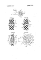
Drawings accompany the disclosure and the various views thereof may be briefly described as:
FIG. 1, a top view of a part constructed in accordance with the invention.
FIG. 2, a sectional view on line 22 of FIG. 1.
FIG. 3, a view of the joint in displaced position.
FIG. 4, a sectional view of a modified construction.
and in which can be mounted the shaft of another part to be articulated to the main ring mount.
The parts are molded together in a manner which provides a continuous web portion 18 having considerably less axial thickness than either the outer ring or the sleeve 16. The axial thickness of this web will depend on the loads that are intended to be carried but it must have a dimension wherein it can be flexed to some degree as the joint is worked. Extending outwardly from this web 18 are concentric double flanges which extend to either side of the web, these flanges having the function of strengthening the web but also serve to limit the pivotal movement of the sleeve 16 by reason of radial contact as the parts are worked. It will be noted that the flanges are tapered from the base portion joined to the web 18 to the outer ends. This facilitates molding but also allows the joint movement desired.
In FIG. 3, the displacement of the sleeve 16 shows the manner in which the radial spaced double flanges 20 will merge toward each other on the cramping side of the movement and ultimately cause a limitation of the motion. They also tend to increase the resistance to some degree as the parts are moved to the extreme positions and to reinforce the entire construction against damage. Otherwise, the parts are such that they allow free motion in any direction with equalized resistance between the outer ring and the inner sleeve in much the same manner as a ball joint.
in H6. 4, a modified construction illustrates a unit having an outer ring 30 and an inner sleeve 32. The intervening resistance elements between these two parts are formed by an undulating relatively thin web 34 which, in cross-section, has three loops 36, 38 and 40, the web being integral with the outer ring and the inner ring at the inner and outer circumferences respectively and completely circumferential in the annular space between parts 30 and 32. This web is reinforced by radial ribs 42 which are secured on an axial line 44 to the inner wall of the outer ring 20. These ribs are secured to the inner sleeve 32 only at the center portion 46 adjacent the point where the web 34 merges with the inner sleeve. The ribs are tapered outwardly from this point to leave gaps 48. It will thus be seen that when the inner sleeve 32 is angled relative to the outer ring 30, the web 34 will stabilize the ribs 42 and provide a certain amount of resistance to the motion. The gaps 48 will allow relatively free motion in a limited angle and beyond this point the motion will be resisted by the compression of both the ribs 42 and the web 34.
The parts in both embodiments above described can be molded from a plastic having a suitable weatherresistant characteristic and life that is required for the particular joint. The flexiblity characteristics can also be adjusted to the particular load requirements which is called for by the application for the joint.
I claim:
1. A joint to serve in the capacity of a vehicle ball joint comprising; an annular outer supporting member, an inner supporting member received generally concentrically within said outer supporting member with a generally annular space therebetween, an annular web interconnecting said members and extending through the annular space therebetween, said web having flexible characteristics allowing cocking of said members relative to each other while providing resistance to said cocking in any direction, said annular web having an axial dimension relatively smaller than the axial dimension of said members, and annular flanges spaced radially from each other and extending axially from said annular web to provide an interference action which resists further cocking from a predetermined degree of generally axial cocking between said members.
2. A joint to serve in the capacity of a vehicle ball joint comprising; an annular outer supporting member, an inner supporting member received generally concentrically within said outer supporting member with a generally annular space therebetween, and an annular web interconnecting said members and extending through the annular space therebetween, said annular web having flexible characteristics allowing cocking of said members relative to each other and providing resistance to said cocking in any direction, said annular web having an undulating cross section throughout its generally radial extent.
3. A joint as defined in claim 2 wherein said outer supporting member, inner supporting member and annular web are a one-piece body of a homogeneously integral nonmetallic material.
4. A joint as defined in claim 2 which also comprises circumferentially spaced generally radially extending ribs received between said members, said ribs being integral with said annular web.
5. A joint as defined in claim 4 in which said ribs are jointed to one of said members by a first portion which is narrowed relative to the axial extent of said ribs, each of said ribs having a second portion adjacent said first portion and generally radially spaced from said one member and positioned for interference with said one member on a predetermined degree of generally axial cocking of said members relative to each other.
6. A joint as defined in claim 1 wherein said outer supporting member, inner supporting member and annular web are a one-piece body of a homogeneously integral nonmetallic material.
said joint functions as a vehicle ball joint.
mg I UNlTED STATES PATENT OFFICE CERTIFIQATE OF CORRECTION Patent No. 3 I841: 772 Dated October 15 1974 Inventor(s) Edward A. Snidar It is certified that enter appears in the above-identified patent and that said Letters Patent are hereby corrected as shown below:
Please correct the name of the assignee to read:
Gulf & Western Manufacturing Company (Michigan) Signed and sealed this 1 4th day of January 1975a (SEAL) Attest:
mom: M. GIBSON JR. 0. MARSHALL DANN Attesting Officer Cozmnissioner of Patents
Claims (7)
1. A joint to serve in the capacity of a vehicle ball joint comprising; an annular outer supporting member, an inner supporting member received generally concentrically within said outer supporting member with a generally annular space therebetween, an annular web interconnecting said members and extending through the annular space therebetween, said web having flexible characteristics allowing cocking of said members relative to each other while providing resistance to said cocking in any direction, said annular web having an axial dimension relatively smaller than the axial dimension of said members, and annular flanges spaced radially from each other and extending axially from said annular web to provide an interference action which resists further cocking from a predetermined degree of generally axial cocking between said members.
2. A joint to serve in the capacity of a vehicle ball joint comprising; an annular outer supporting member, an inner supporting member received generally concentrically within said outer supporting member with a generally annular space therebetween, and an annular web interconnecting said members and extending through the annular space therebetween, said annular web having flexible characteristics allowing cocking of said members relative to each other and providing resistance to said cocking in any direction, said annular web having an undulating cross section throughout its generally radial extent.
3. A joint as defined in claim 2 wherein said outer supporting member, inner supporting member and annular web are a one-piece body of a homogeneously integral nonmetallic material.
4. A joint as defined in claim 2 which also comprises circumferentially spaced generally radially extending ribs received between said members, said ribs being integral with said annular web.
5. A joint as defined in claim 4 in which said ribs are jointed to one of said members by a first portion which is narrowed relative to the axial extent of said ribs, each of said ribs having a second portion adjacent said firSt portion and generally radially spaced from said one member and positioned for interference with said one member on a predetermined degree of generally axial cocking of said members relative to each other.
6. A joint as defined in claim 1 wherein said outer supporting member, inner supporting member and annular web are a one-piece body of a homogeneously integral nonmetallic material.
7. A joint functioning as a vehicle ball joint comprising: a one-piece body of a homogeneously integral nonmetallic plastic material having an annular outer supporting member, an inner supporting member concentric with said outer supporting member with an annular space therebetween and an annular web interconnecting said members through the annular space therebetween, said annular web being sufficiently flexible to permit substantial generally axial cocking of said members relative to each other while resiliently yieldably resisting said generally axial cocking of said members relative to each other in any direction thereof such that said joint functions as a vehicle ball joint.
Priority Applications (8)
| Application Number | Priority Date | Filing Date | Title |
|---|---|---|---|
| US00364013A US3841772A (en) | 1973-05-25 | 1973-05-25 | Joint construction |
| CA180,465A CA990526A (en) | 1973-05-25 | 1973-09-06 | Molded ball joint construction |
| AU60077/73A AU476774B2 (en) | 1973-05-25 | 1973-09-06 | Molded ball joint construction |
| DE19732347699 DE2347699C3 (en) | 1973-05-25 | 1973-09-21 | joint |
| GB4480673A GB1451236A (en) | 1973-05-25 | 1973-09-25 | Joints |
| JP48107056A JPS5237546B2 (en) | 1973-05-25 | 1973-09-25 | |
| ES419117A ES419117A1 (en) | 1973-05-25 | 1973-09-27 | Joint construction |
| FR7334948A FR2231260A5 (en) | 1973-05-25 | 1973-09-28 |
Applications Claiming Priority (1)
| Application Number | Priority Date | Filing Date | Title |
|---|---|---|---|
| US00364013A US3841772A (en) | 1973-05-25 | 1973-05-25 | Joint construction |
Publications (1)
| Publication Number | Publication Date |
|---|---|
| US3841772A true US3841772A (en) | 1974-10-15 |
Family
ID=23432665
Family Applications (1)
| Application Number | Title | Priority Date | Filing Date |
|---|---|---|---|
| US00364013A Expired - Lifetime US3841772A (en) | 1973-05-25 | 1973-05-25 | Joint construction |
Country Status (7)
| Country | Link |
|---|---|
| US (1) | US3841772A (en) |
| JP (1) | JPS5237546B2 (en) |
| AU (1) | AU476774B2 (en) |
| CA (1) | CA990526A (en) |
| ES (1) | ES419117A1 (en) |
| FR (1) | FR2231260A5 (en) |
| GB (1) | GB1451236A (en) |
Cited By (5)
| Publication number | Priority date | Publication date | Assignee | Title |
|---|---|---|---|---|
| EP0010943A1 (en) * | 1978-10-30 | 1980-05-14 | Jr. Alan Dean Tuck | Fluid pressure-driven diaphragm pump |
| US4223176A (en) * | 1979-05-17 | 1980-09-16 | Aluminum Company Of America | Damping spacer with hub interlock and method of making |
| EP0916556A2 (en) * | 1997-11-17 | 1999-05-19 | TAKATA (EUROPE) VEHICLE SAFETY TECHNOLOGY GmbH | Return loop anchor with roller |
| US20020080119A1 (en) * | 1999-06-24 | 2002-06-27 | Johan Ullman | Input device for a computer and a grip arrangement for such a device |
| WO2012080035A1 (en) * | 2010-12-15 | 2012-06-21 | Robert Bosch Gmbh | Fan having a flexible connection to a shaft |
Families Citing this family (1)
| Publication number | Priority date | Publication date | Assignee | Title |
|---|---|---|---|---|
| AU542925B2 (en) * | 1979-03-13 | 1985-03-28 | Regal International, Inc. | Marine fender |
Citations (5)
| Publication number | Priority date | Publication date | Assignee | Title |
|---|---|---|---|---|
| US2126703A (en) * | 1935-10-25 | 1938-08-16 | Metalastik Ltd | Resilient connection |
| US2283440A (en) * | 1940-12-04 | 1942-05-19 | Thompson Prod Inc | Resilient joint construction |
| US2515799A (en) * | 1945-02-08 | 1950-07-18 | Rouy Auguste Louis Mar Antoine | Resilient diaphragm engine bearing |
| US2702087A (en) * | 1951-03-26 | 1955-02-15 | Schwitzer Cummins Company | Fan assembly |
| US3199903A (en) * | 1963-12-23 | 1965-08-10 | Gen Electric | Shock absorbing bearing |
-
1973
- 1973-05-25 US US00364013A patent/US3841772A/en not_active Expired - Lifetime
- 1973-09-06 CA CA180,465A patent/CA990526A/en not_active Expired
- 1973-09-06 AU AU60077/73A patent/AU476774B2/en not_active Expired
- 1973-09-25 GB GB4480673A patent/GB1451236A/en not_active Expired
- 1973-09-25 JP JP48107056A patent/JPS5237546B2/ja not_active Expired
- 1973-09-27 ES ES419117A patent/ES419117A1/en not_active Expired
- 1973-09-28 FR FR7334948A patent/FR2231260A5/fr not_active Expired
Patent Citations (5)
| Publication number | Priority date | Publication date | Assignee | Title |
|---|---|---|---|---|
| US2126703A (en) * | 1935-10-25 | 1938-08-16 | Metalastik Ltd | Resilient connection |
| US2283440A (en) * | 1940-12-04 | 1942-05-19 | Thompson Prod Inc | Resilient joint construction |
| US2515799A (en) * | 1945-02-08 | 1950-07-18 | Rouy Auguste Louis Mar Antoine | Resilient diaphragm engine bearing |
| US2702087A (en) * | 1951-03-26 | 1955-02-15 | Schwitzer Cummins Company | Fan assembly |
| US3199903A (en) * | 1963-12-23 | 1965-08-10 | Gen Electric | Shock absorbing bearing |
Cited By (8)
| Publication number | Priority date | Publication date | Assignee | Title |
|---|---|---|---|---|
| EP0010943A1 (en) * | 1978-10-30 | 1980-05-14 | Jr. Alan Dean Tuck | Fluid pressure-driven diaphragm pump |
| US4223176A (en) * | 1979-05-17 | 1980-09-16 | Aluminum Company Of America | Damping spacer with hub interlock and method of making |
| FR2457027A1 (en) * | 1979-05-17 | 1980-12-12 | Aluminum Co Of America | SHOCK ABSORBER WITH FLANGE LOCK FOR AIRLINES |
| EP0916556A2 (en) * | 1997-11-17 | 1999-05-19 | TAKATA (EUROPE) VEHICLE SAFETY TECHNOLOGY GmbH | Return loop anchor with roller |
| EP0916556A3 (en) * | 1997-11-17 | 2001-05-23 | TAKATA (EUROPE) VEHICLE SAFETY TECHNOLOGY GmbH | Return loop anchor with roller |
| US20020080119A1 (en) * | 1999-06-24 | 2002-06-27 | Johan Ullman | Input device for a computer and a grip arrangement for such a device |
| US6762750B2 (en) * | 1999-06-24 | 2004-07-13 | Johan Ullman | Input device for a computer and a grip arrangement for such a device |
| WO2012080035A1 (en) * | 2010-12-15 | 2012-06-21 | Robert Bosch Gmbh | Fan having a flexible connection to a shaft |
Also Published As
| Publication number | Publication date |
|---|---|
| JPS50142960A (en) | 1975-11-18 |
| AU6007773A (en) | 1975-03-06 |
| JPS5237546B2 (en) | 1977-09-22 |
| DE2347699A1 (en) | 1974-12-12 |
| GB1451236A (en) | 1976-09-29 |
| DE2347699B2 (en) | 1977-06-16 |
| AU476774B2 (en) | 1976-10-07 |
| FR2231260A5 (en) | 1974-12-20 |
| ES419117A1 (en) | 1976-04-16 |
| CA990526A (en) | 1976-06-08 |
Similar Documents
| Publication | Publication Date | Title |
|---|---|---|
| US4671678A (en) | Resilient radial sliding bearing | |
| US5058867A (en) | Cylindrical vibration damping bushing | |
| US3909084A (en) | Ball joint construction | |
| US4767108A (en) | Elastic bushing assembly | |
| US4923312A (en) | Thrust bearing made of synthetic resin | |
| US4072373A (en) | Wheel construction | |
| US4969752A (en) | Thrust bearing made of synthetic resin | |
| KR840000063B1 (en) | Ball-socket joints | |
| CA1271212A (en) | Intermediate bearing for the propeller shaft of a motor vehicle | |
| US3944305A (en) | Roller bearing provided with flanges | |
| JPH06137317A (en) | Turning bearing device | |
| CA1107313A (en) | Thrust washer and combination seal and thrust washer method and apparatus | |
| US4392657A (en) | Belleville spring loaded seal | |
| WO2004070220A1 (en) | Thrust slide bearing | |
| US3279832A (en) | Seal for ball and socket joint | |
| US3841772A (en) | Joint construction | |
| JPS6053208B2 (en) | Angular contact spherical self-aligning bearing | |
| US4385673A (en) | Spherical joint with flexible seals | |
| US2879091A (en) | Ball joint assembly | |
| US4268040A (en) | Thrust washer and combination seal and thrust washer method and apparatus | |
| US2881032A (en) | Combination radial and end-thrust bearing | |
| US6406029B1 (en) | Seal assembly having an encapsulated cone spring | |
| US3149863A (en) | Ball and socket joint | |
| US3107953A (en) | Bushing assembly | |
| US20020172442A1 (en) | Bearing arrangement for a shaft bearing |
Legal Events
| Date | Code | Title | Description |
|---|---|---|---|
| AS | Assignment |
Owner name: O & S MANUFACTURING COMPANY, 777 WEST EIGHT MILE R Free format text: ASSIGNMENT OF ASSIGNORS INTEREST.;ASSIGNOR:GULF & WESTERN MANUFACTURING COMPANY;REEL/FRAME:004188/0956 Effective date: 19831007 |