US4385673A - Spherical joint with flexible seals - Google Patents
Spherical joint with flexible seals Download PDFInfo
- Publication number
- US4385673A US4385673A US06/250,756 US25075680A US4385673A US 4385673 A US4385673 A US 4385673A US 25075680 A US25075680 A US 25075680A US 4385673 A US4385673 A US 4385673A
- Authority
- US
- United States
- Prior art keywords
- seal assembly
- relative
- pivotal movement
- spherical joint
- journal
- Prior art date
- Legal status (The legal status is an assumption and is not a legal conclusion. Google has not performed a legal analysis and makes no representation as to the accuracy of the status listed.)
- Expired - Lifetime
Links
Images

Classifications
-
- B—PERFORMING OPERATIONS; TRANSPORTING
- B62—LAND VEHICLES FOR TRAVELLING OTHERWISE THAN ON RAILS
- B62D—MOTOR VEHICLES; TRAILERS
- B62D55/00—Endless track vehicles
- B62D55/08—Endless track units; Parts thereof
- B62D55/084—Endless-track units or carriages mounted separably, adjustably or extensibly on vehicles, e.g. portable track units
- B62D55/0842—Tracked vehicle with track carriages suspended on three points, e.g. by an equaliser bar
-
- B—PERFORMING OPERATIONS; TRANSPORTING
- B62—LAND VEHICLES FOR TRAVELLING OTHERWISE THAN ON RAILS
- B62D—MOTOR VEHICLES; TRAILERS
- B62D55/00—Endless track vehicles
- B62D55/08—Endless track units; Parts thereof
- B62D55/088—Endless track units; Parts thereof with means to exclude or remove foreign matter, e.g. sealing means, self-cleaning track links or sprockets, deflector plates or scrapers
-
- F—MECHANICAL ENGINEERING; LIGHTING; HEATING; WEAPONS; BLASTING
- F16—ENGINEERING ELEMENTS AND UNITS; GENERAL MEASURES FOR PRODUCING AND MAINTAINING EFFECTIVE FUNCTIONING OF MACHINES OR INSTALLATIONS; THERMAL INSULATION IN GENERAL
- F16C—SHAFTS; FLEXIBLE SHAFTS; ELEMENTS OR CRANKSHAFT MECHANISMS; ROTARY BODIES OTHER THAN GEARING ELEMENTS; BEARINGS
- F16C11/00—Pivots; Pivotal connections
- F16C11/04—Pivotal connections
- F16C11/06—Ball-joints; Other joints having more than one degree of angular freedom, i.e. universal joints
- F16C11/0614—Ball-joints; Other joints having more than one degree of angular freedom, i.e. universal joints the female part of the joint being open on two sides
-
- F—MECHANICAL ENGINEERING; LIGHTING; HEATING; WEAPONS; BLASTING
- F16—ENGINEERING ELEMENTS AND UNITS; GENERAL MEASURES FOR PRODUCING AND MAINTAINING EFFECTIVE FUNCTIONING OF MACHINES OR INSTALLATIONS; THERMAL INSULATION IN GENERAL
- F16C—SHAFTS; FLEXIBLE SHAFTS; ELEMENTS OR CRANKSHAFT MECHANISMS; ROTARY BODIES OTHER THAN GEARING ELEMENTS; BEARINGS
- F16C11/00—Pivots; Pivotal connections
- F16C11/04—Pivotal connections
- F16C11/06—Ball-joints; Other joints having more than one degree of angular freedom, i.e. universal joints
- F16C11/0666—Sealing means between the socket and the inner member shaft
- F16C11/0671—Sealing means between the socket and the inner member shaft allowing operative relative movement of joint parts due to flexing of the sealing means
-
- F—MECHANICAL ENGINEERING; LIGHTING; HEATING; WEAPONS; BLASTING
- F16—ENGINEERING ELEMENTS AND UNITS; GENERAL MEASURES FOR PRODUCING AND MAINTAINING EFFECTIVE FUNCTIONING OF MACHINES OR INSTALLATIONS; THERMAL INSULATION IN GENERAL
- F16C—SHAFTS; FLEXIBLE SHAFTS; ELEMENTS OR CRANKSHAFT MECHANISMS; ROTARY BODIES OTHER THAN GEARING ELEMENTS; BEARINGS
- F16C23/00—Bearings for exclusively rotary movement adjustable for aligning or positioning
- F16C23/02—Sliding-contact bearings
- F16C23/04—Sliding-contact bearings self-adjusting
- F16C23/043—Sliding-contact bearings self-adjusting with spherical surfaces, e.g. spherical plain bearings
- F16C23/045—Sliding-contact bearings self-adjusting with spherical surfaces, e.g. spherical plain bearings for radial load mainly, e.g. radial spherical plain bearings
-
- F—MECHANICAL ENGINEERING; LIGHTING; HEATING; WEAPONS; BLASTING
- F16—ENGINEERING ELEMENTS AND UNITS; GENERAL MEASURES FOR PRODUCING AND MAINTAINING EFFECTIVE FUNCTIONING OF MACHINES OR INSTALLATIONS; THERMAL INSULATION IN GENERAL
- F16C—SHAFTS; FLEXIBLE SHAFTS; ELEMENTS OR CRANKSHAFT MECHANISMS; ROTARY BODIES OTHER THAN GEARING ELEMENTS; BEARINGS
- F16C33/00—Parts of bearings; Special methods for making bearings or parts thereof
- F16C33/72—Sealings
- F16C33/74—Sealings of sliding-contact bearings
-
- F—MECHANICAL ENGINEERING; LIGHTING; HEATING; WEAPONS; BLASTING
- F16—ENGINEERING ELEMENTS AND UNITS; GENERAL MEASURES FOR PRODUCING AND MAINTAINING EFFECTIVE FUNCTIONING OF MACHINES OR INSTALLATIONS; THERMAL INSULATION IN GENERAL
- F16J—PISTONS; CYLINDERS; SEALINGS
- F16J15/00—Sealings
- F16J15/16—Sealings between relatively-moving surfaces
- F16J15/32—Sealings between relatively-moving surfaces with elastic sealings, e.g. O-rings
- F16J15/3268—Mounting of sealing rings
-
- F—MECHANICAL ENGINEERING; LIGHTING; HEATING; WEAPONS; BLASTING
- F16—ENGINEERING ELEMENTS AND UNITS; GENERAL MEASURES FOR PRODUCING AND MAINTAINING EFFECTIVE FUNCTIONING OF MACHINES OR INSTALLATIONS; THERMAL INSULATION IN GENERAL
- F16C—SHAFTS; FLEXIBLE SHAFTS; ELEMENTS OR CRANKSHAFT MECHANISMS; ROTARY BODIES OTHER THAN GEARING ELEMENTS; BEARINGS
- F16C2326/00—Articles relating to transporting
- F16C2326/20—Land vehicles
-
- Y—GENERAL TAGGING OF NEW TECHNOLOGICAL DEVELOPMENTS; GENERAL TAGGING OF CROSS-SECTIONAL TECHNOLOGIES SPANNING OVER SEVERAL SECTIONS OF THE IPC; TECHNICAL SUBJECTS COVERED BY FORMER USPC CROSS-REFERENCE ART COLLECTIONS [XRACs] AND DIGESTS
- Y10—TECHNICAL SUBJECTS COVERED BY FORMER USPC
- Y10T—TECHNICAL SUBJECTS COVERED BY FORMER US CLASSIFICATION
- Y10T403/00—Joints and connections
- Y10T403/32—Articulated members
- Y10T403/32008—Plural distinct articulation axes
- Y10T403/32041—Universal
Definitions
- This invention relates generally to spherical joints and more particularly to a spherical joint having a pair of flexible seals mounted therein.
- Spherical joints wherein a pair of members are connected together for compound movements by a semi-spherical bearing having a journal mounted therein, are normally sealed by a pair of annular seal assemblies disposed on either side of the journal. Sealing of the joint is particularly important in application of the joint to construction vehicles, such as the pivotal joint connecting each end of an equalizer bar to a track roller frame of a track-type vehicle. During operation of the vehicle in the heavy dust-laden environments, the transversely disposed equalizer bar and track roller frame will be subjected to relative rotational movement about a journal pin of the joint and pivotal movement transverse to such rotational movement.
- seal assemblies are subjected to tensile and compressive forces which tend to curtail the service life of the seal assemblies.
- Seal assemblies of this type are illustrated in FIG. 4 of the drawings with each seal assembly comprising a pair of radially disposed retaining rings having an elastomeric seal compressed therebetween.
- the elastomeric seals are subjected to torsional stresses when relative rotational movement occurs between the equalizer bar and track roller frame.
- the relatively tall cross-section of the seal tends to make it difficult to incorporate the seal assembly in certain designs wherein space limitations are critical.
- conventional seal assemblies of this type are expensive to manufacture and install, as well as service, due to their swaged construction and the inability to employ modern manufacturing techniques, such as injection molding, for the fabrication of the elastomeric seal.
- Limitations are also placed on the design of the journal since the inner retaining ring of the seal assembly is press-fitted onto the pin.
- the rather severe operating forces imposed on the elastomeric seal further dictate the need for a relatively soft elastomeric composition for the seal, such as Neoprene, which must be precompressed to enable the seal assembly to counteract high stresses imposed thereon.
- the present invention is directed to overcoming one or more of the problems as set forth above.
- an improved spherical joint comprises a pair of members having a semi-spherical bearing and journal mounted therebetween, with the members being adapted for relative rotational movement about a longitudinal axis of the journal and relative pivotal movement transverse to such rotational movement.
- An annular seal assembly is mounted between the members and on each side of the journal with the improvement comprising means for permitting flexing of the seal assembly to at least substantially prevent stretching or compression thereof in response to the relative pivotal movement between the first and second members.
- the spherical joint is preferably used to connect each end of an equalizer bar to a respective track roller frame of a track-type vehicle.
- the seal assembly includes an elastomeric member mounted between inner and outer rings and a lip seal mounted on the inner ring.
- the seal assembly includes an elastomeric member having a main body portion intersected by an imaginary conical plane and a lip seal mounted in the seal assembly.
- the improved seal assembly thus provides the spherical joint with a long service life, substantially reduces the overall cost thereof in comparison to conventional joints employing standard seal assemblies therein, and provides a highly serviceable seal assembly which satisfies minimum space requirements.
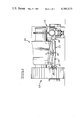
- FIG. 1 is a partially sectioned front elevational view of a track-type vehicle having each end of an equalizer bar pivotally connected to a track roller frame by a spherical joint embodiment of the present invention
- FIG. 2 is an enlarged sectional view through the joint, taken in the direction of arrows II--II in FIG. 1;
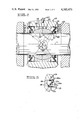
- FIG. 3 is a sectional view illustrating a modification of a seal assembly employed in the joint.
- FIG. 4 is a view similar to FIG. 2, but illustrates a conventional spherical joint.
- FIG. 1 illustrates a track-type vehicle 10, such as a track-type tractor, having a main frame 11 and a pair of laterally spaced track roller frames 12 mounted on either side of the main frame in a conventional manner.
- Forward ends of track roller frames 12 are pivotally connected to main frame 11 by a laterally extending equalizer bar 13, pivotally connected to the main frame by a standard pivot connection 14.
- a spherical joint 15, embodying this invention pivotally connects each lateral end of equalizer bar 13 to a respective track roller frame 12.
- equalizer bar 13 will pivot about pivot joint 14, as indicated by arrow P. Simultaneously therewith, relative pivotal movement P' will normally occur as between each track roller frame 12 and equalizer bar 13. Furthermore and referring to FIG. 2, joint 15 will be also subjected to pivotal movement P", about a pivotal axis A of the joint. Vehicles of this type operate in heavily dust-laden environments, thus requiring that joint 15 be fully sealed to prevent abrasion and potential damage to the bearing surfaces thereof.
- each joint 15 includes an annular bearing 16 secured within a through bore 17, formed through equalizer bar or first member 13.
- a journal 18 is mounted in bearing 16 and is further mounted on a journal pin or second member 19.
- a standard grease fitting 20 and appropriate intercommunicating passages may be formed in joint 15, as shown, to continuously lubricate mating, semispherical bearing surfaces 21 of bearing 16 and surface 18' of journal 18.
- a pair of annular seal assemblies 22 are mounted between equalizer bar 13 and pin 19 on each side of bearing 16 and journal 18 to continuously seal joint 15 during operation thereof.
- Each seal assembly 22 includes means 23 for permitting flexing of seal assembly 22 to at least substantially prevent stretching or compression thereof in response to relative pivotal movement P" (FIG. 2), between equalizer bar 13 and pin 19.
- Means 23 includes a flexible member 24, shown as preferably having a generally Z-shaped cross section in FIG. 2.
- a frusto-conically shaped main body portion 25 of member 24 at least substantially lies in a conical plane C, having its apex at pivot point A of spherical joint 15 which intersects a longitudinal axis L of journal pin 19. It can be seen in FIG. 2 that this construction and arrangement will induce flexing of carrier 24 and, thus, seal assembly 22, rather than any tensioning or compression thereof.
- Member 24 proper may be composed of a flexible elastomeric material, such as a relatively tough urethane compound (e.g., "Hytrel”) which will exhibit a prolonged service life.
- a relatively tough urethane compound e.g., "Hytrel”
- the outside diameter of a main body portion 25 of member 24 may be bonded or otherwise suitably secured to an annular ring 26 which is press-fitted or otherwise suitably secured within a counterbore of bore 17.
- the inside diameter of member 24 may be secured on the periphery of an annular ring 27 which carries an annular lip seal 28 on an outboard side thereof.
- main body portion 25 extends radially inwardly from an outboard end of the seal assembly to an inboard end thereof.
- ring 27 functions as a load transfer member which accomodates the difference in spring rates between main body portion 25 and lip seal 28. Forces developed by the flexing of main body portion 25 are transferred to shaft 19, by passing lip seal 28, so as not to affect its sealing capabilities.
- journal 18 and ring 27 and pin 19 Small running clearances are preferably provided between the inside diameters of journal 18 and ring 27 and pin 19 to allow a slide-in and slide-out pin design facilitating assembly and disassembly for servicing purposes.
- This construction and arrangement further facilitates relative rotational motion between pin 19 and equalizer bar 13 about longitudinal axis L of the pin. Member 24 is thus free from any torsional stresses which would be otherwise imposed thereon.
- a radius R, subscribing a circle centered at pivot point A and intersecting the outside diameters of seal assemblies 22, is desirably greater than approximately ten times a radius R 1 , subscribing a circle centered at pivot point A and indicating variance of the pivot point relative to C and within the latter circle.
- An alternative, preferable design parameter to achieve the desired flexing desiderata is one of varying the cone angle ⁇ 10° relative to the optimum "O" angle wherein conical plane C, containing the major axis of body portion 25, intersects pivot point A. This variance is depicted in FIG. 2 by angle r, between conical planes C' and C".
- the seal material may become subjected to undesirable stretching and/or compression, rather than flexing, to potentially cause premature seal failure. It should be noted that the "hinge action" thus provided by the flexing of seal assembly 22 will allow the shape thereof to change without causing undesirable distortion. This desiderata may be contrasted with the hereinafter described distortion imparted to the prior art seal assembly 22' of FIG. 4 upon operation thereof.
- FIG. 3 illustrates a modification 22a of seal assembly 22 wherein an elastomeric sealing member 24a, substantially similar to member 24, is bonded or otherwise suitably secured between an outer ring 26a and an inner ring 27a. Rings 26a and 27a may be press-fitted within bore 17 of equalizer bar 13 and on the outside diameter of pin 19, respectively, as shown. Thus, ring 27 and lip seal 28 are eliminated. Main body portion 25a of member 24a lies in a conical plane C' and flexes whereby seal assembly 22a functions substantially identically to seal assembly 22.
- Spherical joint 15 finds particular application to the type of environment illustrated in FIG. 1; namely, the pivotal connection between each end of equalizer bar 13 and a respective track roller frame 12.
- seal assembly 22 Upon relative pivoting P' between a track roller frame 12 and equalizer bar 13 (FIG. 1), seal assembly 22 will remain in a stress-free condition of operation since no torsional loads will be placed thereon.
- such relative pivotal movement between equalizer bar 13 and pin 19 will occur between journal 18 and pin 19 and/or between bearing surfaces 21 of the journal and bearing 16. Since ring 27 is suitably clearanced to rotate relative to pin 19, no torsional stresses will be placed on carrier 24.
- FIG. 4 illustrates a standard spherical joint 15' wherein a pair of laterally spaced seal assemblies 22' are subjected to tensile stresses and compressive loads upon relative pivotal movement P", between an equalizer bar 13' and a pin 19'. Furthermore, upon relative rotation between equalizer bar 13 and pin 19 about longitudinal axis L of the pin, elastomeric body portion 25' of each seal assembly 22' will be subjected to torsional stresses, which could affect the desired service life of the seal assemblies.
Landscapes
- Engineering & Computer Science (AREA)
- General Engineering & Computer Science (AREA)
- Mechanical Engineering (AREA)
- Chemical & Material Sciences (AREA)
- Combustion & Propulsion (AREA)
- Transportation (AREA)
- Pivots And Pivotal Connections (AREA)
Abstract
Description
Claims (12)
Priority Applications (1)
| Application Number | Priority Date | Filing Date | Title |
|---|---|---|---|
| US06/250,756 US4385673A (en) | 1980-09-26 | 1980-09-26 | Spherical joint with flexible seals |
Applications Claiming Priority (1)
| Application Number | Priority Date | Filing Date | Title |
|---|---|---|---|
| US06/250,756 US4385673A (en) | 1980-09-26 | 1980-09-26 | Spherical joint with flexible seals |
Publications (1)
| Publication Number | Publication Date |
|---|---|
| US4385673A true US4385673A (en) | 1983-05-31 |
Family
ID=22949008
Family Applications (1)
| Application Number | Title | Priority Date | Filing Date |
|---|---|---|---|
| US06/250,756 Expired - Lifetime US4385673A (en) | 1980-09-26 | 1980-09-26 | Spherical joint with flexible seals |
Country Status (1)
| Country | Link |
|---|---|
| US (1) | US4385673A (en) |
Cited By (15)
| Publication number | Priority date | Publication date | Assignee | Title |
|---|---|---|---|---|
| US4553760A (en) * | 1984-11-19 | 1985-11-19 | Caterpillar Tractor Co. | Flexible seal for a spherical joint |
| US4955741A (en) * | 1988-03-30 | 1990-09-11 | Koyo Seiko Co., Ltd. | Universal joint |
| US5326322A (en) * | 1991-12-09 | 1994-07-05 | Weasler Engineering, Inc. | Cone style universal joint |
| FR2753769A1 (en) * | 1996-09-26 | 1998-03-27 | Caterpillar Inc | Pressurised lubricating oil bearing joint seal for workshop machinery |
| US6298933B1 (en) | 1999-10-08 | 2001-10-09 | Caterpillar Inc. | Equalizer bar stop assembly for limiting movement of the equalizer bar relative to the main frame of a track-type work machine |
| US20050145397A1 (en) * | 2002-12-09 | 2005-07-07 | Michael Robert J. | Moving tracks dozer equalizer link elastomeric bearing assembly |
| US20070151775A1 (en) * | 2005-12-20 | 2007-07-05 | Bedford Billy R | Equalizer bar mounting arrangement |
| US20080157496A1 (en) * | 2006-10-06 | 2008-07-03 | Lefferts Scott R | Vehicle with elastomeric bearing suspension system and elastomeric bearing therefor |
| WO2011150150A3 (en) * | 2010-05-28 | 2012-02-23 | Caterpillar Inc. | Seal assembly and method for forming a seal assembly |
| WO2013022689A1 (en) * | 2011-08-05 | 2013-02-14 | Roller Bearing Company Of America, Inc. | Self-lubricating spherical plain bearing for a vehicle suspension system |
| US20150322999A1 (en) * | 2012-12-19 | 2015-11-12 | Zf Friedrichshafen Ag | Joint device for a motor vehicle |
| US10100779B2 (en) * | 2016-04-09 | 2018-10-16 | United Technologies Corporation | Enhanced durability drive link for high load misalignment |
| US10344802B1 (en) * | 2018-03-16 | 2019-07-09 | Aktiebolaget Skf | Seal assembly for spherical plain bearing |
| US11794828B2 (en) | 2020-06-30 | 2023-10-24 | Soucy International Inc. | Pivot assembly for a ground-contacting wheel assembly |
| US20240125390A1 (en) * | 2022-10-13 | 2024-04-18 | Freudenberg-Nok General Partnership | High pressure offset seal |
Citations (3)
| Publication number | Priority date | Publication date | Assignee | Title |
|---|---|---|---|---|
| US3680924A (en) * | 1970-03-06 | 1972-08-01 | Us Army | Endless track pin assembly |
| US4034996A (en) * | 1975-10-08 | 1977-07-12 | Saitamakiki Co., Ltd. | Ball joint for torque rod |
| US4232754A (en) * | 1979-03-19 | 1980-11-11 | Caterpillar Tractor Co. | Equalizer bar pad construction |
-
1980
- 1980-09-26 US US06/250,756 patent/US4385673A/en not_active Expired - Lifetime
Patent Citations (3)
| Publication number | Priority date | Publication date | Assignee | Title |
|---|---|---|---|---|
| US3680924A (en) * | 1970-03-06 | 1972-08-01 | Us Army | Endless track pin assembly |
| US4034996A (en) * | 1975-10-08 | 1977-07-12 | Saitamakiki Co., Ltd. | Ball joint for torque rod |
| US4232754A (en) * | 1979-03-19 | 1980-11-11 | Caterpillar Tractor Co. | Equalizer bar pad construction |
Cited By (29)
| Publication number | Priority date | Publication date | Assignee | Title |
|---|---|---|---|---|
| JPS6194618U (en) * | 1984-11-19 | 1986-06-18 | ||
| JPH0343460Y2 (en) * | 1984-11-19 | 1991-09-11 | ||
| US4553760A (en) * | 1984-11-19 | 1985-11-19 | Caterpillar Tractor Co. | Flexible seal for a spherical joint |
| US4955741A (en) * | 1988-03-30 | 1990-09-11 | Koyo Seiko Co., Ltd. | Universal joint |
| US5326322A (en) * | 1991-12-09 | 1994-07-05 | Weasler Engineering, Inc. | Cone style universal joint |
| FR2753769A1 (en) * | 1996-09-26 | 1998-03-27 | Caterpillar Inc | Pressurised lubricating oil bearing joint seal for workshop machinery |
| US6298933B1 (en) | 1999-10-08 | 2001-10-09 | Caterpillar Inc. | Equalizer bar stop assembly for limiting movement of the equalizer bar relative to the main frame of a track-type work machine |
| US7861413B2 (en) | 2002-12-09 | 2011-01-04 | Lord Corporation | Method of making a dozer maintenance repair for a dozer equalizer link using an elastomeric bearing assembly |
| US20050145397A1 (en) * | 2002-12-09 | 2005-07-07 | Michael Robert J. | Moving tracks dozer equalizer link elastomeric bearing assembly |
| US20070151775A1 (en) * | 2005-12-20 | 2007-07-05 | Bedford Billy R | Equalizer bar mounting arrangement |
| US7516805B2 (en) * | 2005-12-20 | 2009-04-14 | Caterpillar Inc. | Equalizer bar mounting arrangement |
| US8336896B2 (en) | 2006-10-06 | 2012-12-25 | Lord Corporation | Vehicle with elastomeric bearing suspension system and elastomeric bearing therefor |
| US20080157496A1 (en) * | 2006-10-06 | 2008-07-03 | Lefferts Scott R | Vehicle with elastomeric bearing suspension system and elastomeric bearing therefor |
| US7789407B2 (en) | 2006-10-06 | 2010-09-07 | Lord Corporation | Vehicle with elastomeric bearing suspension system and elastomeric bearing therefor |
| EP2787223A2 (en) | 2010-05-28 | 2014-10-08 | Caterpillar, Inc. | Seal assembly and method for forming a seal assembly |
| WO2011150150A3 (en) * | 2010-05-28 | 2012-02-23 | Caterpillar Inc. | Seal assembly and method for forming a seal assembly |
| CN102918289A (en) * | 2010-05-28 | 2013-02-06 | 卡特彼勒公司 | Seal assembly and method for forming a seal assembly |
| EP2787223A3 (en) * | 2010-05-28 | 2014-11-19 | Caterpillar, Inc. | Seal assembly and method for forming a seal assembly |
| EP2577081A2 (en) * | 2010-05-28 | 2013-04-10 | Caterpillar, Inc. | Seal assembly and method for forming a seal assembly |
| EP2577081A4 (en) * | 2010-05-28 | 2013-12-04 | Caterpillar Inc | Seal assembly and method for forming a seal assembly |
| US8622644B2 (en) | 2010-05-28 | 2014-01-07 | Caterpillar Inc. | Seal assembly and method for forming a seal assembly |
| CN104053592A (en) * | 2011-08-05 | 2014-09-17 | 美国滚柱轴承公司 | Self-lubricating spherical plain bearing for vehicle suspension system |
| WO2013022689A1 (en) * | 2011-08-05 | 2013-02-14 | Roller Bearing Company Of America, Inc. | Self-lubricating spherical plain bearing for a vehicle suspension system |
| US20150322999A1 (en) * | 2012-12-19 | 2015-11-12 | Zf Friedrichshafen Ag | Joint device for a motor vehicle |
| US10280971B2 (en) * | 2012-12-19 | 2019-05-07 | Zf Friedrichshafen | Joint device for a motor vehicle |
| US10100779B2 (en) * | 2016-04-09 | 2018-10-16 | United Technologies Corporation | Enhanced durability drive link for high load misalignment |
| US10344802B1 (en) * | 2018-03-16 | 2019-07-09 | Aktiebolaget Skf | Seal assembly for spherical plain bearing |
| US11794828B2 (en) | 2020-06-30 | 2023-10-24 | Soucy International Inc. | Pivot assembly for a ground-contacting wheel assembly |
| US20240125390A1 (en) * | 2022-10-13 | 2024-04-18 | Freudenberg-Nok General Partnership | High pressure offset seal |
Similar Documents
| Publication | Publication Date | Title |
|---|---|---|
| US4385673A (en) | Spherical joint with flexible seals | |
| US4671678A (en) | Resilient radial sliding bearing | |
| CA1265546A (en) | Flexible seal for a spherical joint | |
| US6231264B1 (en) | Torque rod bearing assembly | |
| US5058867A (en) | Cylindrical vibration damping bushing | |
| CA1187303A (en) | Integrally sealed vibration dampening ball and socket joints | |
| US5181784A (en) | Elastic sliding bearing iii | |
| KR101299817B1 (en) | Cross axis ball and socket joint with sealing ring for cross axis sleeve ends | |
| US4195852A (en) | End face seal assembly | |
| KR960015416B1 (en) | Pivoting bearing for mounting pull rods in motor vehicles | |
| US6435757B1 (en) | Mechanical coupling for elastic axial and radial constraint with torsional freedom, especially for elastic pivots and suspensions and the like | |
| US20070122232A1 (en) | Ball joint assembly | |
| GB2176235A (en) | Ball joint | |
| KR20040098497A (en) | Ball and socket joint | |
| EP1233195A1 (en) | Ball joint seal | |
| CA1151220A (en) | Spring shackle assembly | |
| JPH07113371B2 (en) | Elastomeric slide bearing | |
| US20020071716A1 (en) | Ball joint with angular movement restriction system | |
| JP4118690B2 (en) | Ball joint | |
| CA1156702A (en) | Spherical joint with flexible seals | |
| USRE31298E (en) | Spring shackle assembly | |
| US4276786A (en) | Boot seal | |
| US3316033A (en) | Bearing assembly | |
| CA1074838A (en) | Track joint with combined thrust and seal members | |
| US20020076268A1 (en) | Angular movement restriction bushing for ball joint |
Legal Events
| Date | Code | Title | Description |
|---|---|---|---|
| AS | Assignment |
Owner name: CATERPILLAR TRACTOR CO., A CORP. OF CA., ILLINOIS Free format text: ASSIGNMENT OF ASSIGNORS INTEREST;ASSIGNOR:OLT ARTHUR E. JR.;REEL/FRAME:003880/0697 Effective date: 19800919 |
|
| STCF | Information on status: patent grant |
Free format text: PATENTED CASE |
|
| AS | Assignment |
Owner name: CATERPILLAR INC., 100 N.E. ADAMS STREET, PEORIA, I Free format text: ASSIGNMENT OF ASSIGNORS INTEREST.;ASSIGNOR:CATERPILLAR TRACTOR CO., A CORP. OF CALIF.;REEL/FRAME:004669/0905 Effective date: 19860515 Owner name: CATERPILLAR INC., A CORP. OF DE.,ILLINOIS Free format text: ASSIGNMENT OF ASSIGNORS INTEREST;ASSIGNOR:CATERPILLAR TRACTOR CO., A CORP. OF CALIF.;REEL/FRAME:004669/0905 Effective date: 19860515 |