US3839114A - Method and apparatus for making pile fabric - Google Patents
Method and apparatus for making pile fabric Download PDFInfo
- Publication number
- US3839114A US3839114A US00305028A US30502872A US3839114A US 3839114 A US3839114 A US 3839114A US 00305028 A US00305028 A US 00305028A US 30502872 A US30502872 A US 30502872A US 3839114 A US3839114 A US 3839114A
- Authority
- US
- United States
- Prior art keywords
- fibers
- cut
- strip
- batt
- web
- Prior art date
- Legal status (The legal status is an assumption and is not a legal conclusion. Google has not performed a legal analysis and makes no representation as to the accuracy of the status listed.)
- Expired - Lifetime
Links
- 239000004744 fabric Substances 0.000 title claims abstract description 94
- 238000000034 method Methods 0.000 title claims abstract description 63
- 239000000835 fiber Substances 0.000 claims abstract description 197
- 238000005520 cutting process Methods 0.000 claims abstract description 55
- 239000000463 material Substances 0.000 claims abstract description 32
- 230000033001 locomotion Effects 0.000 claims description 33
- 239000000853 adhesive Substances 0.000 claims description 23
- 230000001070 adhesive effect Effects 0.000 claims description 23
- 238000004519 manufacturing process Methods 0.000 claims description 9
- 230000009471 action Effects 0.000 claims description 7
- 229920000728 polyester Polymers 0.000 claims description 6
- 230000000284 resting effect Effects 0.000 claims description 5
- 239000004033 plastic Substances 0.000 claims description 4
- 239000000470 constituent Substances 0.000 claims description 3
- 230000000717 retained effect Effects 0.000 claims description 3
- 230000036961 partial effect Effects 0.000 claims description 2
- 230000000694 effects Effects 0.000 abstract description 4
- 230000008569 process Effects 0.000 description 6
- 230000007480 spreading Effects 0.000 description 6
- 238000003892 spreading Methods 0.000 description 6
- 238000009960 carding Methods 0.000 description 5
- 244000309464 bull Species 0.000 description 4
- 230000007246 mechanism Effects 0.000 description 4
- 239000000758 substrate Substances 0.000 description 4
- 230000001276 controlling effect Effects 0.000 description 3
- 239000007788 liquid Substances 0.000 description 3
- 230000008901 benefit Effects 0.000 description 2
- 230000015572 biosynthetic process Effects 0.000 description 2
- 230000001680 brushing effect Effects 0.000 description 2
- 230000006835 compression Effects 0.000 description 2
- 238000007906 compression Methods 0.000 description 2
- 238000010276 construction Methods 0.000 description 2
- 230000005484 gravity Effects 0.000 description 2
- 238000010438 heat treatment Methods 0.000 description 2
- 239000002994 raw material Substances 0.000 description 2
- 229910001220 stainless steel Inorganic materials 0.000 description 2
- 239000010935 stainless steel Substances 0.000 description 2
- 229920002994 synthetic fiber Polymers 0.000 description 2
- 238000011282 treatment Methods 0.000 description 2
- QTBSBXVTEAMEQO-UHFFFAOYSA-M Acetate Chemical compound CC([O-])=O QTBSBXVTEAMEQO-UHFFFAOYSA-M 0.000 description 1
- 229920000742 Cotton Polymers 0.000 description 1
- 101100252165 Mus musculus Rnd2 gene Proteins 0.000 description 1
- HRSANNODOVBCST-UHFFFAOYSA-N Pronethalol Chemical compound C1=CC=CC2=CC(C(O)CNC(C)C)=CC=C21 HRSANNODOVBCST-UHFFFAOYSA-N 0.000 description 1
- 229910000831 Steel Inorganic materials 0.000 description 1
- 239000004809 Teflon Substances 0.000 description 1
- 229920006362 Teflon® Polymers 0.000 description 1
- 238000009825 accumulation Methods 0.000 description 1
- 239000003522 acrylic cement Substances 0.000 description 1
- 238000005452 bending Methods 0.000 description 1
- 229920002301 cellulose acetate Polymers 0.000 description 1
- 238000006243 chemical reaction Methods 0.000 description 1
- 239000007795 chemical reaction product Substances 0.000 description 1
- 239000003795 chemical substances by application Substances 0.000 description 1
- 235000019504 cigarettes Nutrition 0.000 description 1
- 239000011248 coating agent Substances 0.000 description 1
- 238000000576 coating method Methods 0.000 description 1
- 239000003086 colorant Substances 0.000 description 1
- 239000011231 conductive filler Substances 0.000 description 1
- 239000004020 conductor Substances 0.000 description 1
- 230000005611 electricity Effects 0.000 description 1
- 229920001821 foam rubber Polymers 0.000 description 1
- 230000006872 improvement Effects 0.000 description 1
- 230000001788 irregular Effects 0.000 description 1
- 239000004816 latex Substances 0.000 description 1
- 229920000126 latex Polymers 0.000 description 1
- 208000020442 loss of weight Diseases 0.000 description 1
- 239000000203 mixture Substances 0.000 description 1
- 230000004048 modification Effects 0.000 description 1
- 238000012986 modification Methods 0.000 description 1
- 239000002985 plastic film Substances 0.000 description 1
- 229920006255 plastic film Polymers 0.000 description 1
- 238000005498 polishing Methods 0.000 description 1
- 238000003825 pressing Methods 0.000 description 1
- 230000002829 reductive effect Effects 0.000 description 1
- 230000001105 regulatory effect Effects 0.000 description 1
- 230000004044 response Effects 0.000 description 1
- 239000008259 solid foam Substances 0.000 description 1
- 230000003068 static effect Effects 0.000 description 1
- 239000010959 steel Substances 0.000 description 1
- 230000001360 synchronised effect Effects 0.000 description 1
- 239000012209 synthetic fiber Substances 0.000 description 1
- 239000004753 textile Substances 0.000 description 1
- 238000009966 trimming Methods 0.000 description 1
- 230000000007 visual effect Effects 0.000 description 1
- 238000011179 visual inspection Methods 0.000 description 1
Images


Classifications
-
- D—TEXTILES; PAPER
- D04—BRAIDING; LACE-MAKING; KNITTING; TRIMMINGS; NON-WOVEN FABRICS
- D04H—MAKING TEXTILE FABRICS, e.g. FROM FIBRES OR FILAMENTARY MATERIAL; FABRICS MADE BY SUCH PROCESSES OR APPARATUS, e.g. FELTS, NON-WOVEN FABRICS; COTTON-WOOL; WADDING ; NON-WOVEN FABRICS FROM STAPLE FIBRES, FILAMENTS OR YARNS, BONDED WITH AT LEAST ONE WEB-LIKE MATERIAL DURING THEIR CONSOLIDATION
- D04H11/00—Non-woven pile fabrics
-
- Y—GENERAL TAGGING OF NEW TECHNOLOGICAL DEVELOPMENTS; GENERAL TAGGING OF CROSS-SECTIONAL TECHNOLOGIES SPANNING OVER SEVERAL SECTIONS OF THE IPC; TECHNICAL SUBJECTS COVERED BY FORMER USPC CROSS-REFERENCE ART COLLECTIONS [XRACs] AND DIGESTS
- Y10—TECHNICAL SUBJECTS COVERED BY FORMER USPC
- Y10T—TECHNICAL SUBJECTS COVERED BY FORMER US CLASSIFICATION
- Y10T156/00—Adhesive bonding and miscellaneous chemical manufacture
- Y10T156/10—Methods of surface bonding and/or assembly therefor
- Y10T156/1052—Methods of surface bonding and/or assembly therefor with cutting, punching, tearing or severing
- Y10T156/1062—Prior to assembly
- Y10T156/1075—Prior to assembly of plural laminae from single stock and assembling to each other or to additional lamina
- Y10T156/1077—Applying plural cut laminae to single face of additional lamina
Definitions
- a pile fabric and method and apparatus for making such pile fabric by applying on a backing fabric or other type of web or sheet material support a layer of cut mono-filament fibers of substantially equal length disposed perpendicularly to the face of the backing fabric, each of the fibers being adherently secured to the backing fabric at one end of the fiber.
- the fibers are derived from a multi-ply batt of continuous filament spread tow wherein the filaments are all arranged generally parallel to one another.
- the batt is advanced in the direction in which the filaments extend to a cutting station in synchronism with clamping and cutting elements operable at the cutting station to successively cut the batt at equal intervals in a plane transverse to the feed of the batt.
- Each strip of fibers thus cut from the batt is pushed in a direction parallel to the plane of the cut into an accumulator chamber until it abuts the rear of the previous strip so loaded in the chamber.
- the cut strips merge in the chamber and are advanced therethrough by the cut strips being successively pushed into the chamber.
- the continuous layer of fibers which emerges from the exit end of the chamber is brought into contact with an adhesively coated backing fabric or other pile support to form the pile fabric.
- an endless belt knife and associated clamp, pusher and gate are employed to effect the clamping, cutting and strip advancing steps.
- This invention relates to a method and apparatus for manufacturing pile articles such as velvet. carpets, apparel linings, artificial turf and the like.
- An object of this invention is to provide an improved method and apparatus for making pile fabric which assures that the pile fibers are of uniform length and individually secured to a backing in such a manner that they are firmly bonded thereto to produce a pile fabric of good quality and appearance at an exceedingly low cost.
- Another object is to provide an improved method and apparatus for manufacturing fabric of the above character directly from continuous filamentary materials such as crimped or uncrimped tow so as to obviate the hitherto customary conversion of such raw material into a carded web by cutting or chopping the tow into short randomly oriented staple, followed by carding the cut staple and forming the same into the carded web.
- FIG. 1 is a schematic elevational view taken partly in vertical section of one form of the first stage of the method of the invention, and apparatus employed therein, wherein continuous tow is opened and spread progressively, and then wound into a roll of single ply tow in accordance with the present invention.
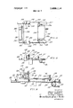
- FIG. 2 is a schematic elevational view taken partly in vertical section of the second stage of the method and one embodiment of a machine for practicing this stage of the method of the invention.
- FIG. 3 is a fragmentary schematic elevational view taken partly in vertical section of a second embodiment of a machine for practicing the second stage of the method of this invention, with the clamping and cutting elements being shown in open position and the batt advanced to cutting position.
- FIGS. 4-9 inclusive are fragmentary schematic views taken partly in vertical section illustrating the sequence of operation of the machine of FIG. 3.
- FIG. is a fragmentary semi-schematic perspective view of a machine incorporating the elements of the machine illustrated in FIGS. 3-9.
- FIG. 11 is a side elevational view of the machine of FIG. 10.
- FIG. 12 is a fragmentary schematic side elevational view of a third embodiment of a machine of the present invention for practicing the second stage of the method of this invention.
- FIG. 13 is a fragmentary schematic side elevational view of a modified creel and feeder of the present invention for forming and feeding a multi-ply batt of continous filament spread tow to the infeed conveyor of the machine shown in FIG. 3.
- FIG. 14 is a fragmentary top plan view of a modified accumulator chamber construction also in accordance with the present invention.
- FIG. 15 is a side elevational view of the structure shown in FIG. 14.
- FIG. 16 is a vertical section taken on the line XVI- XVI of FIG. 14 and slightly enlarged in scale thereover illustrating the top plate of the accumulator chamber in raised position.
- FIG. 1 illustrates the first stage of the method of making pile fabric in accordance with the present invention, this stage preferably being performed by a machine for opening continuous filamentary materials as disclosed in US. Pat. Nos. 3,328,850 and/or 3,380,131, which are incorporated herein by reference.
- This tow spreading machine designated generally by the reference numeral 10, is fed with raw material from a bale 12 of tow which may be made up of continuous (up to several miles in length) crimped or uncrimped filaments extruded from synthetic plastic materials such as polyester or cellulose acetate.
- the initial filament groups are of a contorted or crimped nature, i.e., the profile or side elevation of an individual monofilament is irregular (i.e., not straight) when the filament is viewed from at least one side.
- Steam bulked continuous tow, steam crimped continuous filament tow, gear crimped continuous filament tow or knife edge crimped continuous tow are examples of such contorted monofilamentary material.
- a wide variety of polymeric compositions may be employed, such as those man-made filaments listed by way of examples in US. Pat. No. 3,334,006.
- Such man-made fibers hitherto have usually been supplied for further processing, such as being cut into staple fiber length, baled, then opened by carding and converted into sliver and then into yarn or cigarette filter material.
- the initial mono filament material is often supplied as tows which are bundles of generally parallel continuous filaments, each such bundle containing a large number of such filaments generally well over 500, e.g., 6,000 to 500,000.
- this monofilamentary material is commercially available as a band of tow 14 consisting of say one thousand strands laid side-by-side (parallel) in untwisted form but somewhat randomly intermingled.
- the band of tow 14 which may have an initial width of approximately 2 inches, is drawn upwardly from bale 12 over stationary guide bars 16 and 18 and then through a banding jet 20 such as that disclosed in US.
- the band of tow 14 passes through a confined zone defined by two generally parallel arcuate walls 22 and 24 where it is subjected across its whole width to an air stream or streams which spread the tow to a width of about five or six inches.
- the partially spread tow next passes under a guide bar 25 and then is pulled through nip rolls 26 and 28 and a further set of nip rolls 30 and 32.
- An electrically grounded bar 34 may be employed in advance of rolls 30 and 32, if desired.
- the tow After leaving rolls 30 and 32, the tow passes through a second air spreader 36, then around feed rolls 38 and 40, thence through a third air spreader 42, then around another set of feed rolls 44 and 46 and finally through the fourth air spreader 48.
- a second air spreader 36 After leaving rolls 30 and 32, the tow passes through a second air spreader 36, then around feed rolls 38 and 40, thence through a third air spreader 42, then around another set of feed rolls 44 and 46 and finally through the fourth air spreader 48.
- the spread tow issuing from spreader 48 is in the form of a wide web 50, for example 6 feet in width, with the individual filaments parallelized, i.e., relatively uniformly latterly spaced with a minimum ofintermingling and overlapping such that web 50 is essentially a single ply having a thickness equal to the diameter of its constitutent monofilament material.
- Web 50 is formed into a single-ply roll, preferably by folling up the web into a tubular coil on a mandrel 52 to thereby form a relatively loose roll 54 of the single ply spread tow material. This may be accomplished by feeding web 50 onto the upper run 56 of an endless belt supported and driven by end rolls S8 and 60.
- Mandrel 52 may be supported for free rotation by loosely confining its protruding ends between two pairs of stationary vertical uprights 62 and 64. Mandrel 52 is urged by gravity downwardly so as to rest on web 50 and press it against run 56 so that the mandrel and the successive convolutions of web 50 being wound thereon are frictionally driven from belt 56 to thus wind up batt 54.
- the second stage in the method of this invention includes as the next step the formation of a multi-ply batt of continuous filament spread tow.
- a plurality of rolls 70, 72, 74, 76, 78, 80, 82 and 84 are placed on a suitable support stand or creel 86 in a series of horizontal and vertical rows.
- Each of the rolls 70, 74, 78 and 82 are individually supported for free rotation on a removable axle 88 extending between a pair of uprights 90 (only one being shown) which flank the ends of the rolls to thereby form one vertical row of rolls.
- Another pair of uprights 92 similarly support rolls 72, 76, 80 and 84 in another vertical row, preferably at the same elevation as their respective companion rolls 70, 74, 78 and 82.
- a third pair of uprights 94 support a series of guidebars 96, 98, 100 and 102 which extend horizontally therebetween.
- the upper surface of each guidebar 96, 98, 100 and 102 is disposed slightly above the level of the upper surfaces of the associated horizontal row of rolls 7072, 74-76, 78-80 and 82-84 respectively.
- the single ply web 70 unwound from roll 70 overlies the like web 72 unwound from roll 72, and these two single webs merge where they meet at guidebar 96.
- the merged webs 70 and 72 then extend at an angle downwardly to a presser roll 104.
- the multi-ply parallel monofilament batt 110 is gripped between belt 106 and the lower run 112 of a companion apron conveyor 114 and fed in the direction of its constituent monofilaments upwardly between the infeed guide elements 216 and 220 of a cutting machine indicated generally by the reference numeral 200 which, except for the infeed conveyor, is identical to the modified machine 200 described in greater detail subsequently herein in conjunction with FIGS. 3-11 inclusive. Accordingly, a brief description of machine 200 will suffice at this point to complete the description of the second stage of the method of this invention.
- Machine 200 has a cutting element comprising a motor driven knife assembly including a horizontally reciprocated carriage in which a cutter preferably in the form of an endless belt knife 226 is supported by a pair of horizontally spaced bull wheels for continuous travel in a path normal to the direction of reciprocation of the carriage, the axes of the bull wheels being parallel to the direction of carriage reciprocation.
- Machine 200 also has clamping and accumulating elements comprising a pusher 280, a movable backstop 290 and a plate 284 spaced horizontally above a table 218 to form with the table a guide or accumulator chamber 219 having a width approximately equal to that of batt and closed at the sides by appropriate side plates 219 (FIGS. 10 and 11).
- cutter 226 operates to successively cut from the upper, leading end of batt 110 a series of strips or bands of fibers.
- Pusher 280 thereafter pushes the cut strip into the guide wherein the successively cut'strips form a continuous mass 124 of upright fibers which issue from the exit of the guide as a layer of closely packed fibers to be applied onto the backing fabric 126 which is fed by feed rolls 128, 130 and 132.
- a suitable adhesive 134 may be applied to the appropriate surface of fabric 126 by means of a doctor blade hopper 136.
- the lower run 137 of the fabric runs parallel to and spaced above the upper run 138 of an endless belt conveyor 140 which is trained around drive rollers 142 and 144.
- Roll 128 presses fabric 126 against the upper ends of the stacked array of fibers, and the fabric conveyor together with conveyor 140 conveys the fibers (which are now adhered at the upper ends to fabric 126) to the right as viewed in FIG. 2 through an appropriate oven or dryer schematically indicated at 146 which assists in curing the adhesive.
- the finished fabric 148 exits between roller 130 and guide roll 144, and may be cut to size and given suitable finishing treatments as will be well understood by those skilled in the art. Further details of the structure and operation of machine 200 may be had by referring the subsequent description of machine 200.
- the method of the present invention provides an improved pile fabric and offers substantial economies in production.
- the method of this invention eliminates several intermediate processing steps and associated equipment hitherto employed in making cemented pile fabric, namely, cutting the synthetic filament into cut staple stock in a chopper machine, then carding the staple on a carding machine, combing the doffer of the carding machine and accumulating the combed fleece on an accumulator to form a web of carded fibers.
- each of the filmanets in batt 110 is continuous (and may in fact extend for several miles), the fibers in each strip severed by knife 226 are all of uniform length, which is readily adjusted by altering the feeding and cutting set-up. This in turn means that each fiber in the mass of cut fibers 124 as it exits from the guide will have its upper end flush with the other upper ends of the fibers, and therefore each fiber will be individually secured by the adhesive to the backing 126.
- cut pile fabric made from non-continuous filament such as from fibers or rovings or other similar material made up in batts of discontinuous fibers, the fabric 148 has greater strength, longer life and better appearance.
- fabric 148 suffers very little loss from shedding during subsequent brushing and/or electrifier treatments since there are no short fibers unattached to the backing to cause a loss of weight in the fabric as well as to detract from its appearance. Hence the scrap rate in the entire process is reduced practically to zero as compared to a percent or percent fiber loss when cemented cut pile fabric is produced from a carded, discontinuous fiber batt.
- the method of this invention contemplates the use of continuous filament spread tow, it is limited to the use of man-made fibers, but this is not a serious limitation since such fibers now are available in a vast array of synthetic materials, weights and colors and in fact today represent the preferable material for pile fabrics.
- the concept of merging single ply spread tow, after the spreading process, into a multi-ply batt of spread tow 110 offers great versatility in selection of the number of plys.
- the batt thus formed has a very soft, fluffy, dense characteristic highly suitable for cutting into strips and feeding onto a backing or support for the pile fiber to produce a fleecy type pile fabric.
- the density of the fabric can be easily varied by appropriate adjustment of the compression produced by the juxtaposed apron infeed belts 106 and 112. Further variation in density is obtained by regulating the rate of loading of the guide chamber of machine 200 versus the take-away rate of the outfeed conveyor 140 and associated backing feed rollers 128, 130 and 132.
- the multi-ply batt 110 by utilizing a plurality of continous tow spreading machines 10 connected so that each single ply web exiting from each machine is fed directly in a converging relation to the other batts to the inlet end of the infeed conveyor 108 of machine 200.
- the production rate of the continuous tow spreading machine 10 is such that one machine can keep up with a pile fabric manufacturing machine 200 utilizing a multiple roll creel.
- the rolls will become depleted in sequence and thus can be replaced one at a time without shutting down machine 200.
- FIGS. 3-11 inclusive A preferred embodiment of the apparatus of the present invention particularly well adapted for practicing the second stage of the method of invention is semischematically illustrated in FIGS. 3-11 inclusive.
- machine 200' has an infeed conveyor which merges and feeds the multi-ply batt 110 in a manner similar to machine 200.
- the infeed conveyor includes the nip roll 204, an apron conveyor 206 and two pairs of opposed feed rolls 208, 210, 212 and 214 intermittently driven so as to advance batt 110 upwardly against the vertical guide surface 217 of stationary guide plate 216 fixed to the front edge of table 218.
- rolls 208 and 210 are rotated slightly faster than rolls 212 and 214 to insure that the run of batt 110 between these two sets of feed rolls is maintained in a related condition.
- roll 204 is driven at a speed which insures that batt is not under tension on the upper run of conveyor 206.
- Guide 216 extends horizontally a distance slightly greater than the width or lateral dimension of batt 110.
- Ma chine 200 also includes movable pressure plate 220 which reciprocates horizontally from the open position shown in FIG. 3 to the clamping position shown in FIG. 4. The upper edge 221 of the vertical clamping surface 222 of plate 220 moves in a horizontal plane flush with the upper edge 224 of guide 216.
- the cutting elements of machine 200' is an endless belt knife 226 trained around horizontally spaced bull wheels 227 and 227 (FIG. 10) rotatable about horizontal axes 228 and 228'.
- the lower run 230 of belt knife 226 is disposed parallel to and spaced very closely above the horizontal plane defined by edges 221 and 224.
- knife 226 is a part of a commercially available "FEMCO" splitting head assembly manufactured and sold by The Falls Engineering and Machine Company of Cuyahoga Falls, Ohio, and such is the type hitherto used for cutting or slicing large blocks of solid foam rubber into sheets.
- Such a knife assembly includes a carriage or framework 232 (FIGS.
- Knife 226 is a continuous band of high quality steel which runs continuously during the opera tion of the machine and is constantly sharpened while running by a pair of dressing wheels 236 and 238 each driven by an associated motor 240 and 242 respectively supported on framework 232 adjacent the upper run 244 of knife 226.
- Lower run 230 preferably runs in a guide (not shown) and its cutting edge protrudes from the guide toward batt 110.
- Upper run 244 constitutes the return run and does not run in a guide.
- the entire cutting blade assembly is supported for horizontal movement by three rods 246, 248 and 250 fixed to the knife framework 232 and protruding from the front and rear thereof over suitable support members of the frame 252 of machine 200.
- Rods 246 and 250 are fixed to the opposite lower corners of the knife framework 232 and respectively extend through linear bearings 254, 256, 258 and 260 mounted on frame members 251 and 251.
- Coil springs 262 and 264 respectively encircle rods 246 and 250 and are mounted to bias framework 232 rearward or to the left as viewed in FIG. 11 towards its retracted position shown in FIGS. 3 and 11.
- Knife 226 is driven on this cutting stroke by a cam follower 270 (FIGS. 10 and 11) fixed at one end to framework 232 and tracking at its other end on a suitable cam 272.
- cam 272 is driven continuously at a given speed by a motor 274 and shaft 276 connected by flexible drive element 278 to the motor.
- Shaft 276 is suitably journalled on frame 252 and extends across the frame to drive a cam and follower (not shown) which are duplicates of cam 272 and follower 270 and located at the other end of framework 232.
- Pusher 280 (FIGS. 3 and 11) is carried on the knife framework 232 above blade run 230 for travel with framework 232.
- Pusher 280 is co-extensive laterally of machine 200 with pressure plate 220 and has an upright flange 282 the upper edge of which is disposed to just clear the undersurface of plate 284 during forward travel of pusher 280 as best seen in FIG. 8.
- Pusher 280 is supported very closely above the surface of run 230 by the plungers 286' of a pair of air cylinders 286 carried by struts 285 on knife framework 232, only one such strut and cylinder being shown in FIGS. 10 and 11.
- These cylinders are operable to reciprocate pusher 280 from a retracted position wherein the front face of the vertical leg 282 is disposed forward of the cutting edge of run 230 (FIGS. 3, 4, 9 and 11) to an extended position wherein leg 282 enters the accumulator chamber 219 and is disposed about six inches past the knife block edge 224 of guide 216 (FIG. 8).
- Each of the plungers 286' of air cylinders 286 has a suitable lost motion connection (shown only in FIG.
- pusher 280 which includes a compression coil spring 287 housed within a blind bore of the larger member 286a of the telescopic two-piece plunger 286 so as to bias the smaller member 286b of plunger 286 to the right as viewed in FIG. 3.
- Member 28617 has a head 2866 which is normally forced against a shoulder 286d by spring 287 to positively limit expansion of plunger 286'.
- Plunger 286 is normally fully extended except when pusher 280 is pushed back from it clamping position shown in FIG. 5 to the position shown in FIG. 6 against the force of springs 287 to accomplish the retrograde motion explained in more detail subsequently herein in connection with FIG. 6.
- pressure plate 220 is movably supported on framework 232 for travel therewith but can move relative to the framework 232 through a limited travel. This is accomplished by supporting plate 220 by a pair of guide rods 288 (only one of which is shown in FIGS. 10 and 11) these rods sliding in supports 289 fixed to framework 232 and carrying coil springs which bias plate 220 toward guide 216 and against stops when framework 232 is fully retracted to the position shown in FIG. 3.
- the fiber cutting and clamping mechanism of machine 200 also includes backstop 290 which is carried by a vertically reciprocable plunger 292 of a pneumatic cylinder 294 mounted on a carriage plate 296 which in turn is supported for horizontal movement above table 218 by a pair of rods 297 (only the right hand rod being shown in FIGS. 10 and 11) sliding in supports 298 mounted on the machine frame 252.
- the end of rod 298 remote from plate 296 carries a cam follower 299 which tracks in a groove 300 in the side of a cam 301 which is driven from shaft 276.
- Backstop 290 has a vertical face 302 (FIG. 3) which is positioned flush with the vertical face 217 of guide 216 at one position of the cam controlled horizontal motion of backstop 290, as shown in FIG.
- Cam 301 actuates backstop 290 horizontally through a cycle of three positions: from the initial backstop position of FIG. 3 toward and over run 230 of the knife blade to the strip cut-off position shown in FIG. 6, and then horizontally to a strip release position just in front of the entrance to the accumulator chamber 219 as shown in FIG. 7, and then to the FIG. 3 backstop postiion.
- backstop 290 is raised by rods 292 when in its strip release position to a pusher clearance position of FIG. 8, and then lowered to the FIG. 7 position after being cleared by pusher 280, as indicated by the dotted lines in FIGS. 3 and 9.
- the lower edge of stop 290 is lifted clear of the under surface of plate 284.
- the lower edge of stop 290 is spaced closely above the surface of table 218, with just enough clearance to permit the lower run 230 of knife 226 to pass between stop 290 and table 218.
- Machine 200 downstream of the accumulator chamber 219 has the previously described apron conveyor 140 and feeding and guiding rolls 128 and 132 for feeding backing fabric 126.
- a suitable adhesive 134 preferably latex in liquid form or an acrylic adhesive such as that sold under te trademark RHOPLEX by Rhon & Haas Company, may be applied to the surface of fabric 126 to be juxtaposed to the cut fibers 124 by passing the fabric 126 over a plate 312 and beneath the superposed trough 136 which has an apertured bottom wall adapted to meter the liquid adhesive onto the surface of fabric 126.
- the backing fabric 126 may be any suitable textile or plastic film material such as osnaburg cotton sheeting, polyester spun bond such as that sold by E. I.
- Trough 136 also serves as a doctor blade to spread the adhesive evenly over the surface of the fabric.
- the subsequent downstream equipment may include conventional finishing equipment (not shown) such as an infrared heating oven for accelerating the curing of the adhesive, as well as electrifying, brushing and/or polishing equipment, selvage trimmers, piece cutters, etc.
- Machine 200 is operated through a cycle of motions in sequence and synchronism as described hereinafter with reference to FIGS. 39 inclusive by a suitable control mechanism as will be well understood by those skilled in the art.
- cams 316 and 318 driven by shaft 276 may be designed to operate microswitches of an electrical control unit 319 which is operably connected to a solenoid air valve to control the actuation of pusher 280 by air cylinder 286, and likewise to the solenoid valve controlling air cylinder 294 for controlling the raising and lowering of gate 290.
- control unit 318 may be suitably connected to a solenoid operated air cylinder 320 (FIGS.
- ratchet 324 imparts intermittent rotation to the infeed conveyor 206 and the feed rolls 208-214 in synchronism with the operation of knife 226 and clamping elements 220, 280 and 290 of the machine.
- the drives for the outfeed conveyor 140 and the backing fabric feed rolls 128, 130 and 132 may be intermittent from ratchet 324 or continuous and taken directly from shaft 276, or a separate drive may be provided for conveyor and rolls 128-132 under the control of a variable speed motor drive unit to facilitate adjustment of the fabric take-out speed.
- Machine 200 is thus operated through a cycle of operations illustrated in sequence in FIGS. 3-9 to perform the preferred embodiment of the second stage of the method of the invention.
- clamping and knife elements are in the start position shown in FIG. 3, it will be noted that pressure plate 220 and pusher 280 are vertically aligned, and that the lower run 230 of knife 226 is retracted away from the stationary plate 216 into a retracted position relative to pusher 280 and pressure plate 220.
- Gate 290 is vertically aligned with guide plate 216 and is disposed closely adjacent the upper edge 224 thereof.
- These parts 216, 220, 280 and 290 thus define a guideway for receiving the multi-ply continuous tow batt 110 vertically upwardly therebetween, the batt being fed to a cutting position as shown in FIG. 3 by the incremental or intermittent drive of the feed rolls 2082l4.
- the height of the upper end of the batt above the plane of cut may be set as desired, say anywhere between one-half inch and one and one-half inches, depending upon the height of the pile fiber desired in the finished fabric.
- batt 110 is clamped both above and below the plane of travel knife blade 230 by horizontal movement of plunger 280 and pressure plate 220 toward gate 290 and guide 216 respectively.
- This motion is accomplished by the pair of cams 272 driving the knife framework 232 forward.
- the vertical flanges of these members 220 and 280 stay out in front of the cutting edge of blade 230 due to the pressure of the biasing springs acting between these members and the supporting framework 232.
- blade run 230 continues moving to the right with framework 232, it performs the cutting operation illustrated in FIG. 5 where run 230 is shown at the end of its horizontal travel in the cutting direction.
- This forward motion of blade 230 combined with the very rapid travel of the continuously sharpened blade in a direction perpendicular to the plane of the drawing, effects a quick, clean cut off of a strip 110 of fibers from batt 110 with little or no tearing, frizzled ends or stretching of the fibers.
- the cutting edgeof knife run 230 at the end of its cutting stroke is positioned between gate 290 and guide 216, and with the heavier denier filament materials the cutting edge normally will have penetrated entirely through batt 110, and thus will have effected a complete severing of a cut strip of fibers 110.
- backstop 290 is advanced a short distance to the left as viewed in FIG. 6, on the order of one-quarter of an inch. This presses the cut strip 110 of the left, pressing pusher 280 back along with it, and thus insures that those fibers in a zone along the side of the batt adjacent block 216 are swept across the cutting edge of the knife blade and thus fully and completely severed.
- Pusher 280 is able to yield to the left as gate 290 is moved to the left because the telescopic plunger 286 of the air cylinder 286 can retract slightly due to the provision of the aforementioned lost motion connection and biasing spring 287, this action compressing the internal back-up spring 287 due to the greater force exerted by backstop 290 over- 10 coming the back-up spring force during this slight rearward movement of pusher 280.
- backstop 290 is moved horizontally very rapidly to the right as viewed in FIG. 7, while plunger 280 is allowed to regain its position shown in FIG. 5 at a slower rate.
- This causes a rapid enlargement of the space between plunger 280 and stop 290, thereby allowing the strip to bloom, that is, allowing the previously latterly compressed mass of fibers in the cut strip 110' to expand latterly due to their resiliency as the clamping pressure is released.
- this blooming'step reduces the frictional engagement of the right hand edge of the strip 110' with the adjacent face of stop 290 so that the tendency of the cut strip 110 to be dragged upwardly along with stop 290 is substantially eliminated when the same is lifted in the next step shown in FIG. 8 to clear the entrance to accumulator chamber.
- gate 290 is lifted to the position shown in FIG. 8 and then air cylinders 286 are supplied with compressed air via solenoid valves controlled by control mechanism 319.
- strip 110' is pushed into the chamber it butts against the previously loaded strip 110' and pushed the same forward (to the right) in the chamber, thereby advancing the mass of fibers in the chamber.
- This successive loading of cut strips and the frictional pull exerted by take-out conveyor serves to advance the mass of upright fibers 124 onto the upper run 138 of the conveyor.
- the fibers preferably are cut about one-thirty-two of an inch longer than the vertical spacing between the juxtaposed surfaces of table 218 and plate 284. This has been found to provide enough of an interference fit between the mass of fibers and the floor and ceiling of chamber 219 to frictionally retain the fibers in upright position without excessive bending of the fiber tips.
- Cover 284 preferably has a smooth, fiat undersurface and may be made of stainless steel, or it may be a chrome-plated machined surface, and is preferably an electrical conductor with an electrical ground connection 284' (FIG. 3) to bleed off static electricity from the cut fibers.
- Table 218 may be similarly constructed and also has an electrical ground connection 218' (FIG. 3).
- the horizontal dimension of the accumulator chamber from entrance to exit, or from left to right as viewed in FIGS. 4-9, is preferably on the order of about 8 inches to 14 inches, but this can vary considerably according to fiber height, rate of production and denier of the fiber.
- the drive for conveyor 140 may be synchronized so as to have intermittent motion timed with the cutting action of machine 200', and more particularly with the loading of cut strips into the entrance end of the accumulator chamber 219'. It is also possible to drive outfeed conveyor 140 with a continuous motion at a speed with is an average based on the rate at which strips are loaded into the accumulator chamber.
- rate of advance of conveyor 140 and the rate at which strips are loaded into chamber 219 determines the density of the fibers in the chamber as well as the amount of re-expansion of the mass of fibers as they advance toward the apron 138 of conveyor 140. This in turn determines the density of the fibers on conveyor 140 and thus in the end product, and can be readily and precisely controlled within wide limits.
- the knife framework 232 is retracted by springs 262, as permitted by the movement of cams 272, to return blade run 230 to the position shown in FIG. 9.
- Simultaneously plunger 280 is retracted to its home position, by air cylinder 286 as well as by the return movement of framework 232, and pressure plate 220 by moving with the knife framework or carriage 232 also returns to its home position.
- pusher 280 is retracted and moved to the position shown in FIG. 9
- backstop 290 is lowered and moved to the left to its home position.
- the machine then begins another cycle under the control of control mechanism 319.
- the backing material 126 is fed by roll 128 at the same rate and in the same manner as the juxtaposed upper run 138 of conveyor 140, either intermittently or continuously, as the case may be.
- roll 128 is spaced above upper run 138 by a distance sufficient to provide a slight squeeze of the backing fabric 126 against the upper ends of fibers 124 carried on run 138, on the order of about one thirty-second of an inch interference.
- Conveyor 140 carries the backing with the cut fibers adhesively secured thereto through a suitable curing oven which may be equipped with Calrod heating elements suspended over the backing fabric to thereby radiantly heat the backing material to cure the adhesive.
- Suitable feed rollers and material handling 7 equipment may be provided downstream of the oven or heater to tension the backing by the proper amount relative to the speed of the feed roller 142 and backing roller 128.
- the machine 200 or 200' of the invention may be modified with respect to the accumulator chamber and backing fabric feed as shown schematically in FIG. 12 without departing from the scope of the present invention.
- the machine of FIG. 12 includes all of the previously described batt feeding, cutting, clamping, pusher and gate structure of machine 200 and hence the same has been omitted for clarity.
- the modified machine has a fabric assembly table 400 with a horizontal flat upper surface 402 adapted to support a horizontal run of the backing fabric 126 which is being advanced toward the right as viewed in FIG. 12 by suitable advancing rolls (not shown) located downstream of the oven (also not shown).
- the supply roll 404 of the backing fabric is disposed beneath table 400 and fabric 126 is fed from this roll and also coated with an adhesive while being fed beneath the table to a guide roll 406 disposed beneath the accumulator chamber.
- the axially protruding ends of the shaft 408 on which roll 404 is wound are supported on a stand 410 with each end of the shaft 408 resting on a cross bar 412 and laterally restrained between a pair of uprights 414.
- Roll 404 is thus free to rotate about a horizontal axis as the fabric is withdrawn from the top of the roll and fed over a series of suitably supported freely rotatable guide rolls 416, 418, 420, 422 and 424 on its way to roll 406.
- rolls 416-424 are positioned to cause the backing fabric 126 to travel in a generally S-shaped path as viewed from the side so that the underside of the fabric as it is withdrawn from roll 404 is inverted in traversing roll 420.
- this surface is facing upwardly as it traverses a horizontally disposed fiat backing plate 426 positioned between and slightly above rolls 420 and 422.
- An adhesive hopper and doctor blade 428 similar in construction and operation to hopper 136 described previously, is supported over plate 426 so that a suitable liquid adhesive 134 is applied to the surface of fabric 126 which faces upwardly at this point.
- a drip pan 430 may be positioned beneath the portion of the fabric running from roll 422 to roll 406 to catch any adhesive drippage from the now downwardly facing coated side of the fabric.
- the adhesive coated side of fabric 126 is again inverted in traveling around roll 406 so as to face upwardly where it meets the cut mass of fibers 124.
- Roll 406 is positioned to feed the coated surface of fabric 126 flush with the upper surface of table2l8 so that the fibers 124 are adhered at their lower ends to fabric 126 where the fibers and fabric meet just beyond the edge 432 of table 218.
- the above-described undertable feed of the backing fabric 126 is advantageous in that it takes advantage of what in some cases is otherwise unused space beneath the table, positions the adhesive hopper 428 where it is easily accessible for refilling and below the finished pile fabric so it cannot contaminate the pile fabric being produced on the machine, and eliminates the need for conveyor 140 by having the backing fabric 126 serve as the support and conveyor for the fibers as they are transported thereon to the curing oven.
- This arrangement is also an improvement from the standpoint of facilitating visual inspection of the mass of fibers 124 as they exit from the accumulator chamber so that any malfunctioning can be readily and quickly detected.
- the modified apparatus of FIG. 12 also illustrates another form of top plate for the accumulator chamber pursuant to the present invention, i.e., an endless flexible belt 434 trained taut around guide rolls 436 and 438 positioned respectively above table 400 and table 218 for rotation about horizontal axes.
- Roll 436 is suitably supported in fixed position so that the lower run 440 or belt 434 is spaced above the upper surface 402 of the table by a distance about one thirty-second of an inch less than the combined vertical dimension of fibers 124 and fabric 126.
- the front roll 438 is journalled for rotation on a shaft 442 which in turn is supported at its ends by a pair of air cylinders, only one air cylinder 444 being shown in FIG. 12.
- shaft 442 extends through the eye of a piston rod 446 which extends upwardly to a connection with a piston of cylinder 444, and the other end of shaft 442 is similarly supported.
- Each cylinder 444 is pivotally suspended at its upper end on a pin 446 secured to a support bracket 448.
- Cylinders 444 thus are adapted to raise and lower the entrance end of belt 434, the same being shown in its lowermost position in FIG. 12. ln this position, the undersurface of lower run 440 at roll 438 is spaced above the upper surface of table 218 and fabric 126 by the same distance as top plate 284 of the previously described embodiment, i.e., so that run 440 is parallel to table 218, or by a slightly smaller distance pursuant to the practice with plate 502 described hereinafter.
- the cut strips of fibers accumulated beneath run 440 have a slight interference fit between run 440 and table 218 and between run 440 and the upper run of the fabric 126.
- Belt 434 is preferably positively driven in synchronism with movement of fabric 126.
- the frictional engagement of the upper ends of the fibers with run 440 can be utilized to cause belt 434 to rotate counterclockwise.
- the lower run 440 thus moves with the mass of fibers 124 so that the fibers experience little or no sliding friction between run 440 and the upper run of fabric 126.
- a back-up plate 454 supported by the shafts of rolls 436 and 438 may be superimposed on run 440 to present upward bowing thereof.
- the entrance end of run 440 is pivoted about the axis of roll 436 to raise run 440 above the height of the cut mass 124 of fibers at the entrance end of the accumulator chamber by actuating cylinders 444 just prior to a cut strip of fibers being pushed beneath guide roll 438 by pusher 280. After the strip of fibers has been pushed against the previously cut strip of fibers,
- cylinders 444 are operated to lower roll 438 to the position shown in FIG. 12.
- Pusher 280 is then retracted as described previously in con- 5 junction with FIGS. 8 and 9.
- the height of flange 282 of pusher 280 is such so as to just clear the underside of belt 434 when in its lowermost position.
- belt 434 With this top wall pivotal lifting arrangement there is a minimum disturbance of the cut strip of fibers as they are advanced against the previously cut strip in the accumulator chamber. Moreover, the successive raising and lowering of belt 434 causes the lower run 440 thereof to impart a light tamping action against the upper ends of the mass of fibers 124.
- belt 434 is made of canvas coated with Teflon plastic material containing an electrically conductive filler for grounding purposes, and the rolls 436 and 438 are spaced about 18 inches apart.
- the lower run 440 may be stretched taut between rolls 436 and 438 and is thus otherwise unsupported with respect to back up.
- the machine of the invention may be modified at the input end thereof by the addition of a batt forming station located between creel 86 and infeed apron conveyor 206. It has been found that there should be no tension or drafting effect occurring in the infeed of the batt 110 to machine 200 or 200',
- Each of the protruding ends 470 of the axle or roll 460 extends between an associated pair of upright guides 472 and 474 so that roll 460 can rotate freely in response to the frictional drag of the batt 110 thereagainst. However, roll 460 is unrestrained vertically so that the full weight of roll 460 is effective to nip batt 110 against the lower roll 462.
- Motor 466 is preferably a variable speed motor which may be set by its speed control to produce the drawing force to pull the webs from the creel 86 at a rate sufficient to feed the batt 110 to conveyor 206 such that batt 110 exerts little or no back tension on the infeed conveyor 206 and downstream feed rolls 208 and 210.
- this feed rate is preferably adjusted to maintain a slight downward sag in the portion of batt 110 extending between rolls 460-462 and roll 204 so that there is slack in the batt as it enters between roll 204 and conveyor 206.
- FIGS. 14, 15 and 16 illustrate a third form of accumulation chamber in accordance with the present invention which may be substituted for the fixed chambers of machines 200 or 200 or for the endless belt type chamber described in conjunction with FIG. 12.
- the accumulator station 500 of this embodiment includes two rigid plate members, the previously described stationary bottom'plate 218 and a movable top wall 502.
- the chamber is open at its sides as well as at its exit and entrance ends.
- the top wall or cover 502 of the chamber is a relatively heavy guage stainless steel plate which may be suitably reinforced by a superimposed framework attached thereto (not shown).
- the underside 504 of plate 502 is polished to a mirror finish.
- Plate 502 extends laterally beyond the side edges of table 218 so that its end edges are disposed over the side rails 251 and 251 of the machine framework 252, as best seen in FIG. 14. It will also be seen in FIG. 14 that the longitudinal edges 124a and 124b of the mass of fibers 124 are disposed inwardly of the side edges of table 218 by a distance of at least 1 inch. Plate 502 may be approximately l4 inches wide (the dimension taken in the plane of the drawing between the entrance edge 506 and the exit edge 508 of plate 502).
- Movable cover plate 502 serves to hold the cut fibers in the accumulator chamber as the mass of cut fibers 124 is accumulated therein and fed out to the conveyor 140 for adhesion to the backing fabric as explained in conjunction with machine 200'.
- the density of the mass of fibers 124 is increased while in transit through the accumulator chamber by controlling the rate of infeed of the cut strips relative to the take-away rate of conveyor 140. Hence there is a tendency for the cut strip last loaded into the chamber to spring or pop back when the pusher 280 is retracted after loading the cut strip into the chamber.
- cover 502 limits or prevents such pop-back and keeps the mass of fibers vertically clamped under light interference fit pressure as they are advanced to the accumulator chamber. Also, if the cut strips were not thus restrained from above by cover 502, they would tend to bulge upward when the entire mass is squeezed during the loading of a cut strip into the entrance end of the accumulator chamber.
- Plate 502 is supported adjacent its exit edge 508 by a pair of threaded bolts .510 and 512 which extend through apertures in plate 502 and are adjustably locked in position by a pair of lock nuts 514 and 516 respectively disposed above and below plate 502.
- the lower ends of bolt 510 and 512 rest slidably on side rails 251 and 251' respectively.
- the entrance edge 506 of plate 502 is raised and lowered by a pair of air cylinders 518 and 520 fixedly secured to support brackets 522 and 524 respectively which are part of the stationary framework of the machine.
- Each air cylinder has its piston 526 (FIG. 16) connected by a rod 528 to a bracket 529 affixed to the upper side of plate 502, the eye of the piston rod slidably receiving the shank of the bracket shaft therethrough with a loose clearance to accommodate the pivotal movement of plate 502 relative to the vertical movement of rod 528.
- the upper and lower limits of the pivotal travel of plate 502 are determined by an adjustable stop structure comprising a threaded bolt 530 (FIG. 16) fixed at one end to the upper surface of plate 502 and extending upright therefrom through a slot in a stationary plate 532 secured to bracket 524.
- a pair of lock nuts 534 are threadably carried on stud 530 above plate 532, and another pair of lock nuts 536 are carried on stud 530 below plate 532.
- Air cylinders 518 and 520 are activated in any suitable manner as by a mechanically driven cam which actuates a microswitch connected in circuit with a solenoid valve which in turn controls the flow of air to the cylinders.
- cam and control switches may be conveniently grouped with cams 316 and 318 and switch 319 described in conjunction with FIG. 10, as will be well understood by one skilled in the art from the preceding description.
- the batt is sequentially cut into strips as described in conjunction with machine 200 and 200 and then the microswitches which control the forward loading motion of pusher 280 and the lifting motion of air cylinders 518 and 520 are actuated simultaneously.
- the entrance end or edge 506 of cover 502 is lifted from its lowermost position (broken lines, FIG. 16) toward its uppermost position (solid lines, FIG. 16).
- cover 502 During such pivotal movement of cover 502, its delivery end remains substantially a fixed height above table 218. For the example given, this height is adjusted such that the spacing between the upper surface of table 218 and the portion of undersurface 504 of cover 502 adjacent its rear edge 508 is equal to or slightly greater than the cut height of the pile fibers, or preferably eleven-sixteenths of an inch in the case of fibers cut to five-eighths of an inch. Hence in the raised position of cover 502, the undersurface 504 thereof is inclined upwardly relative to table 218 as shown in solid lines in FIG.
- entrance edge 506 is spaced one-sixteenth to one-eighth of an inch less than the height of the cut fibers in its lowermost position, and in its raised position is at least flush with the cut height of the fibers, but preferably is raised slightly thereabove.
- the undersurface of the outlet end of cover 502 is preferably spaced from the polished metallic electrically conductive and grounded surface of table 218 by a distance at least equal to the cut height of the fiber but preferably is one-sixteenth of an inch above the fiber cut height.
- a movable top plate 502 constructed as described above will provide greatly improved results in terms of preventing tip-over of the cut strips of fibers as they are pushed into the accumulator chamber, as well as preventing or reducing random disorientation of the fibers in the cut strips.
- the aforementioned tamping action is also imparted by plate 502 to the plurality of cut strips of fibers after they have been merged into the accumulator chamber, this tamping occurring respectively on each strip each time a cut strip of fibers is loaded into the accumulator chamber during a cycle of motions described previously, but due to the inclination of the cover, the tamping becomes lighter as the strip is moved toward the outlet of the accumulator chamber.
- the movable top plate 502 thus allows the density of the fibers to be doubled in the accumulator chamber without the disorientation of the fibers which might otherwise occur with a fixed top plate.
- the first stage of the method of the present invention i.e., providing a source of continuous spread tow in the form of a web having a plurality of generally parallel synthetic monofilament continuous fibers
- One fabric produced by the method and machine of the present invention as described previously herein thus comprises a novel cemented pile fabric in that it consists of a substrate made up of a backing material and a coating of adhesive on one surface thereof, and a high pile extending from one face of this substrate.
- the pile consists of a mass of crimped synthetic cut monofilament fibers derived from spread tow. The fibers each have one end in adhering engagement with the adhesive. and are arranged generally perpendicular to the plane of the substrate and thus extend therefrom generally parallel to one another a uniform distance from the substrate.
- a method of making pile fabric comprising the steps of:
- a source of tow comprising at least one web made up of a plurality of continuous filaments oriented side-by-side in a generally coplanar array with the longitudinal axes of its constituent filaments generally parallel and loosely joined together solely by the random mechanical frictional adherence of laterally adjacent filaments; feeding said tow web while so oriented and loosely joined to a cutting station;
- step (a) further comprises providing a multi-ply batt of spread tow made up of a plurality of layers of spread tow arranged with the filaments of each layer generally parallel to and extending in the same direction as the filaments of the other layer or layers with said layers loosely joined together solely by the random mechanical frictional adherence of laterally adjacent filaments of laterally adjacent layers, and wherein steps (b) and (c) are performed on said multi-ply batt with said batt being fed in step (b) in the direction of the longitudinal axes of the filaments thereof.
- step (d) further comprises the step of releasing said cut strip of fibers from being clamped after said cutting step (c) while said strip is resting on a supporting surface to allow the cut strip of fibers to laterally expand in the direction of the cutting action, and then immediately pushing said expanded strip on said surface laterally into contact with the immediately preceding cut strip in a mass of fibers made up of previously cut strips.
- step (a) further comprises providing a multi-ply batt of spread tow made up of a plurality of layers of crimped synthetic monofilament spread tow arranged with the monofilaments of each layer generally parallel to the monofilaments of the other layer or layers.
- said spread tow comprises polyester plastic material in the range from about 3 to 6 denier.
- step (a) further comprises providing a plurality of single plies of said webs each wound up in a roll, arranging a plurality of said rolls on a support in spaced relation to one another for rotation about the respective axes of the individual rolls and with the axes generally parallel, feeding a plurality of webs one from each of said rolls in the direction of the longitudinal axes of the monofilaments thereof to a point of convergence whereby said plurality of single ply webs derived from said rolls are superimposed to form a multi-ply batt of spread tow made up of a plurality of layers of spread tow arranged with the mono-filaments of each layer generally parallel to and extending in the same direction as the monofilaments of the other layer or layers.
- said cutting step (c) further comprises severing said batt of tow at successive equally spaced increments by providing an endless running band knife having at least one straight blade run, relatively moving said knife and said batt to cause said one run of said blade to sequentially cut through said batt and at high speed in a straight path across said batt.
- said accumulating step (d) further comprises the step of releasing said cut strip of fibers under partial restraint by moving said gripping elements apart after said cutting step (c) while said strip is resting on a supporting surface to allow the cut strip of fibers to laterally expand, and then immediately pushing said expanded strip on said surface laterally into contact with a mass of fibers made up of previouslycut strips.
- an accumulator chamber disposed adjacent said cutting station and having a flat surface for receiving said strips of cut fibers severed from said web by said knife
- a guide plate disposed in advance of said knife blade relative to the advancement of said web and having an edge disposed closely adjacent the plane of reciprocating travel of said knife blade and flush with said chamber surface.
- said backstop is aligned flush with said guide plate and said pusher and said pressure plate are aligned flush with one another and retracted from said backstop and guide plate respectively,
- said web is advanced to bring its free end a given distance past said plane of blade travel corresponding to the height of cut of the strip to be severed from said free end of the web
- said blade is advanced across and through the thickness of said clamped web to cut a strip of fibers therefrom,
- said backstop is elevated above the path of travel of said pusher to release said cut strip
- said pusher is advanced to push the cut strip along said chamber surface into the accumulator chamber, and I g. said backstop, pusher and pressure plate are returned to their respective positions set forth in subpara'graph (a) hereinabove.
- said flat surface of said accumulator chamber is defined by a bottom plate extending horizontally and adapted to support a plurality of the cut strips of fibers thereon. and said chamber also includes a cover disposed above said bottom plate.
- said method comprising the further steps of supporting said cover with the edge thereof adjacent the exit end of said chamber spaced from said bottom plate a distance at least approximately equal to the theoretical cut height of the fibers in the cut strips and such that said plate can pivot about a horizontal axis located adjacent said exit end of said cover and extending perpendicular to the direction of movement of said pusher to thereby raise and lower the entrance edge of said cover between upper and lower positions spaced from the bottom plate by distances respectively at least equal to and slightly less than theoretical cut height of the fibers of said strips, pivoting said cover to lift said edge to said upper position prior to the cut strip being pushed into said chamber by said pusher and pivoting said cover to lower said edge to said lower position prior to withdrawing said pusher from said chamber during each cycle or motion of the pusher.
Landscapes
- Engineering & Computer Science (AREA)
- Textile Engineering (AREA)
- Treatment Of Fiber Materials (AREA)
- Preliminary Treatment Of Fibers (AREA)
- Nonwoven Fabrics (AREA)
Priority Applications (9)
| Application Number | Priority Date | Filing Date | Title |
|---|---|---|---|
| GB1820473A GB1335970A (en) | 1970-03-17 | 1970-12-29 | Apparatus for cutting pile fibres |
| GB6140670A GB1335969A (en) | 1970-03-17 | 1970-12-29 | Fabric manufacture |
| FR7102500A FR2083335B3 (OSRAM) | 1970-03-17 | 1971-01-26 | |
| BE762053A BE762053A (fr) | 1970-03-17 | 1971-01-26 | Procede et machine de fabrication de tissu a poils |
| LU62489D LU62489A1 (OSRAM) | 1970-03-17 | 1971-01-26 | |
| CA103,896A CA943447A (en) | 1970-03-17 | 1971-01-28 | Method and apparatus for making pile fabric |
| NL7102025A NL7102025A (OSRAM) | 1970-03-17 | 1971-02-16 | |
| DE19712111122 DE2111122A1 (de) | 1970-03-17 | 1971-03-09 | Vorrichtung und Verfahren zur Herstellung eines Sammelstoffes |
| US00305028A US3839114A (en) | 1970-03-17 | 1972-11-09 | Method and apparatus for making pile fabric |
Applications Claiming Priority (2)
| Application Number | Priority Date | Filing Date | Title |
|---|---|---|---|
| US2033870A | 1970-03-17 | 1970-03-17 | |
| US00305028A US3839114A (en) | 1970-03-17 | 1972-11-09 | Method and apparatus for making pile fabric |
Publications (1)
| Publication Number | Publication Date |
|---|---|
| US3839114A true US3839114A (en) | 1974-10-01 |
Family
ID=26693331
Family Applications (1)
| Application Number | Title | Priority Date | Filing Date |
|---|---|---|---|
| US00305028A Expired - Lifetime US3839114A (en) | 1970-03-17 | 1972-11-09 | Method and apparatus for making pile fabric |
Country Status (8)
| Country | Link |
|---|---|
| US (1) | US3839114A (OSRAM) |
| BE (1) | BE762053A (OSRAM) |
| CA (1) | CA943447A (OSRAM) |
| DE (1) | DE2111122A1 (OSRAM) |
| FR (1) | FR2083335B3 (OSRAM) |
| GB (2) | GB1335970A (OSRAM) |
| LU (1) | LU62489A1 (OSRAM) |
| NL (1) | NL7102025A (OSRAM) |
Cited By (17)
| Publication number | Priority date | Publication date | Assignee | Title |
|---|---|---|---|---|
| US3944451A (en) * | 1973-07-10 | 1976-03-16 | Societe Anonyme Dite B.T.B. Benoit Le Tapis Brosse | Method of and apparatus for making a plush-type cloth |
| US3979251A (en) * | 1974-03-06 | 1976-09-07 | Firma Otto Golze & Sohne, Kokosweberei | Apparatus for producing a pile carpet |
| US4120713A (en) * | 1976-06-21 | 1978-10-17 | A/S Weston Taeppefabrik | Process and apparatus for the continuous production of a fibrous web-like pile product |
| US4351691A (en) * | 1980-11-24 | 1982-09-28 | Schwartz Jack M | Apparatus for making a tufted product |
| US5302228A (en) * | 1991-04-11 | 1994-04-12 | David Holland | Apparatus and method for making V-groove insulation and tank wrap |
| EP0791455A3 (de) * | 1995-12-21 | 1998-05-13 | Ruedi Reinhard | Verfahren zum kontinuierlichen Herstellen eines Teppichs |
| US6112384A (en) * | 1997-04-07 | 2000-09-05 | Barnes; Michael A. | Multi-color fiber fluff products and method and apparatus for making same |
| US7026048B1 (en) | 1997-04-07 | 2006-04-11 | Barnes Michael A | Multi-color fiber fluff products and method and apparatus for making same |
| US7181843B1 (en) * | 1995-09-28 | 2007-02-27 | United Technologies Corporation | Method of manufacturing a brush seal |
| US20100126412A1 (en) * | 2008-11-25 | 2010-05-27 | Ford Global Technologies, Llc | Fiber Transfer Apparatus for Laminating Fiber-Reinforced Sheet Molding Compound |
| US20120125474A1 (en) * | 2009-04-17 | 2012-05-24 | Ten Cate Systems B.V. | Device for producing a fibre mat by weaving |
| EP3192643A1 (en) * | 2016-01-08 | 2017-07-19 | The Boeing Company | Cutter blades for automated fiber placement machines |
| CN112540018A (zh) * | 2019-09-20 | 2021-03-23 | 核工业理化工程研究院 | 纤维毛丝收集装置及其使用方法 |
| CN113146696A (zh) * | 2021-04-21 | 2021-07-23 | 安徽博泰塑业科技有限公司 | 一种pvc管的切割废料处理机构 |
| CN113183218A (zh) * | 2021-04-21 | 2021-07-30 | 安徽博泰塑业科技有限公司 | 一种pvc管的定位切割装置 |
| CN116176007A (zh) * | 2023-02-13 | 2023-05-30 | 中国航空制造技术研究院 | 一种消除铺放机构重力扰动的铺放辊压力控制方法及系统 |
| CN120516788A (zh) * | 2025-07-24 | 2025-08-22 | 厦门一诺得复合材料有限公司 | 一种碳纤维带卷绕切割装置 |
Families Citing this family (2)
| Publication number | Priority date | Publication date | Assignee | Title |
|---|---|---|---|---|
| DE3900796A1 (de) * | 1989-01-12 | 1990-07-19 | Asea Brown Boveri | Anordnung zur vermeidung der transformatorsaettigung bei betrieb an einem u-umrichter |
| CN110732966A (zh) * | 2019-09-29 | 2020-01-31 | 盐城市华森机械有限公司 | 一种砂纸机尾料张紧装置 |
Citations (8)
| Publication number | Priority date | Publication date | Assignee | Title |
|---|---|---|---|---|
| US2792051A (en) * | 1954-08-12 | 1957-05-14 | Giroud Freres Ets | Machines for the manufacture of pile articles |
| US3085922A (en) * | 1959-01-19 | 1963-04-16 | Du Pont | Porous flexible self-supporting sheet material and method of making same |
| GB1031333A (OSRAM) * | 1963-07-09 | 1966-06-02 | Etablissements Giroud Freres Les Successeurs De Hugues Giroud & Cie. | |
| US3278363A (en) * | 1962-12-17 | 1966-10-11 | Couquet Pierre | Apparatus for continuously manufacturing pile articles |
| US3293105A (en) * | 1963-01-22 | 1966-12-20 | Du Pont | Pile article |
| US3477889A (en) * | 1965-03-25 | 1969-11-11 | Btb Benoit Tapis Brosse | Method and apparatus for making nonwoven pile fabrics |
| US3479241A (en) * | 1963-10-07 | 1969-11-18 | Btb Benoit Tapis Brosse | Apparatus for making nonwoven pile carpets |
| US3580761A (en) * | 1966-12-02 | 1971-05-25 | Phillips Petroleum Co | Method of forming nonwoven articles by fusing strands to a base |
-
1970
- 1970-12-29 GB GB1820473A patent/GB1335970A/en not_active Expired
- 1970-12-29 GB GB6140670A patent/GB1335969A/en not_active Expired
-
1971
- 1971-01-26 FR FR7102500A patent/FR2083335B3/fr not_active Expired
- 1971-01-26 LU LU62489D patent/LU62489A1/xx unknown
- 1971-01-26 BE BE762053A patent/BE762053A/xx unknown
- 1971-01-28 CA CA103,896A patent/CA943447A/en not_active Expired
- 1971-02-16 NL NL7102025A patent/NL7102025A/xx unknown
- 1971-03-09 DE DE19712111122 patent/DE2111122A1/de active Pending
-
1972
- 1972-11-09 US US00305028A patent/US3839114A/en not_active Expired - Lifetime
Patent Citations (8)
| Publication number | Priority date | Publication date | Assignee | Title |
|---|---|---|---|---|
| US2792051A (en) * | 1954-08-12 | 1957-05-14 | Giroud Freres Ets | Machines for the manufacture of pile articles |
| US3085922A (en) * | 1959-01-19 | 1963-04-16 | Du Pont | Porous flexible self-supporting sheet material and method of making same |
| US3278363A (en) * | 1962-12-17 | 1966-10-11 | Couquet Pierre | Apparatus for continuously manufacturing pile articles |
| US3293105A (en) * | 1963-01-22 | 1966-12-20 | Du Pont | Pile article |
| GB1031333A (OSRAM) * | 1963-07-09 | 1966-06-02 | Etablissements Giroud Freres Les Successeurs De Hugues Giroud & Cie. | |
| US3479241A (en) * | 1963-10-07 | 1969-11-18 | Btb Benoit Tapis Brosse | Apparatus for making nonwoven pile carpets |
| US3477889A (en) * | 1965-03-25 | 1969-11-11 | Btb Benoit Tapis Brosse | Method and apparatus for making nonwoven pile fabrics |
| US3580761A (en) * | 1966-12-02 | 1971-05-25 | Phillips Petroleum Co | Method of forming nonwoven articles by fusing strands to a base |
Cited By (20)
| Publication number | Priority date | Publication date | Assignee | Title |
|---|---|---|---|---|
| US3944451A (en) * | 1973-07-10 | 1976-03-16 | Societe Anonyme Dite B.T.B. Benoit Le Tapis Brosse | Method of and apparatus for making a plush-type cloth |
| US3979251A (en) * | 1974-03-06 | 1976-09-07 | Firma Otto Golze & Sohne, Kokosweberei | Apparatus for producing a pile carpet |
| US4120713A (en) * | 1976-06-21 | 1978-10-17 | A/S Weston Taeppefabrik | Process and apparatus for the continuous production of a fibrous web-like pile product |
| US4351691A (en) * | 1980-11-24 | 1982-09-28 | Schwartz Jack M | Apparatus for making a tufted product |
| US5302228A (en) * | 1991-04-11 | 1994-04-12 | David Holland | Apparatus and method for making V-groove insulation and tank wrap |
| US7181843B1 (en) * | 1995-09-28 | 2007-02-27 | United Technologies Corporation | Method of manufacturing a brush seal |
| EP0791455A3 (de) * | 1995-12-21 | 1998-05-13 | Ruedi Reinhard | Verfahren zum kontinuierlichen Herstellen eines Teppichs |
| US6112384A (en) * | 1997-04-07 | 2000-09-05 | Barnes; Michael A. | Multi-color fiber fluff products and method and apparatus for making same |
| US6632755B1 (en) | 1997-04-07 | 2003-10-14 | Michael A. Barnes | Multi-color fiber fluff products and method and apparatus for making same |
| US7026048B1 (en) | 1997-04-07 | 2006-04-11 | Barnes Michael A | Multi-color fiber fluff products and method and apparatus for making same |
| US20100126412A1 (en) * | 2008-11-25 | 2010-05-27 | Ford Global Technologies, Llc | Fiber Transfer Apparatus for Laminating Fiber-Reinforced Sheet Molding Compound |
| US8196631B2 (en) * | 2008-11-25 | 2012-06-12 | Ford Global Technologies, Llc | Fiber transfer apparatus for laminating fiber-reinforced sheet molding compound |
| US20120125474A1 (en) * | 2009-04-17 | 2012-05-24 | Ten Cate Systems B.V. | Device for producing a fibre mat by weaving |
| EP3192643A1 (en) * | 2016-01-08 | 2017-07-19 | The Boeing Company | Cutter blades for automated fiber placement machines |
| US9950477B2 (en) | 2016-01-08 | 2018-04-24 | The Boeing Company | Cutter blades for automated fiber placement machines |
| CN112540018A (zh) * | 2019-09-20 | 2021-03-23 | 核工业理化工程研究院 | 纤维毛丝收集装置及其使用方法 |
| CN113146696A (zh) * | 2021-04-21 | 2021-07-23 | 安徽博泰塑业科技有限公司 | 一种pvc管的切割废料处理机构 |
| CN113183218A (zh) * | 2021-04-21 | 2021-07-30 | 安徽博泰塑业科技有限公司 | 一种pvc管的定位切割装置 |
| CN116176007A (zh) * | 2023-02-13 | 2023-05-30 | 中国航空制造技术研究院 | 一种消除铺放机构重力扰动的铺放辊压力控制方法及系统 |
| CN120516788A (zh) * | 2025-07-24 | 2025-08-22 | 厦门一诺得复合材料有限公司 | 一种碳纤维带卷绕切割装置 |
Also Published As
| Publication number | Publication date |
|---|---|
| GB1335970A (en) | 1973-10-31 |
| LU62489A1 (OSRAM) | 1971-08-11 |
| DE2111122A1 (de) | 1971-09-30 |
| FR2083335A3 (OSRAM) | 1971-12-17 |
| CA943447A (en) | 1974-03-12 |
| BE762053A (fr) | 1971-07-26 |
| GB1335969A (en) | 1973-10-31 |
| NL7102025A (OSRAM) | 1971-09-21 |
| FR2083335B3 (OSRAM) | 1973-10-19 |
Similar Documents
| Publication | Publication Date | Title |
|---|---|---|
| US3839114A (en) | Method and apparatus for making pile fabric | |
| US3493452A (en) | Apparatus and continuous process for producing fibrous sheet structures | |
| US4379189A (en) | Nonwoven textile fabric with fused face and raised loop pile | |
| US3957555A (en) | Method of making pile fabric having an adhesive substrate | |
| CA2058987C (en) | Method and device for manufacturing textile products from fibres and/or filaments, products obtained | |
| US4259400A (en) | Fibrous padding material and process for its manufacture | |
| US4179776A (en) | Method and apparatus for deregistering and processing an open synthetic tow into fiber-filled articles | |
| DE2018501A1 (de) | Verfahren zum Herstellen von Samtstoffen od.dgl | |
| IL22483A (en) | Non-woven fabrics | |
| US20020124936A1 (en) | Method and apparatus for the manufacture of composite sheets | |
| US3819469A (en) | Stitched nonwoven webs | |
| US3740282A (en) | Process for making artificial leather from lapped fibrous structures | |
| DE3881345T2 (de) | Vorrichtung und Verfahren zum Verpacken von Garn sowie Garnpackung. | |
| US3309252A (en) | Method and apparatus for producing pile fabric | |
| US2101905A (en) | Pile fabric and process for making the same | |
| US4457055A (en) | Method for forming needled, non-woven fiber padding | |
| US3230584A (en) | Methods and apparatus for making strands, rovings, yarns and the like | |
| US2592201A (en) | Manufacture of pile fabrics | |
| US2358368A (en) | Method and apparatus for making pile fabrics | |
| US5168000A (en) | Flat textile body | |
| US3943028A (en) | Apparatus and process for manufacturing non-woven textile pile | |
| US3847691A (en) | Pile fabrics and methods and apparatus for the production thereof | |
| US3867219A (en) | Method of making pile fabrics from a block of pile material | |
| US2584702A (en) | Method and apparatus for the production of glass fiber mats | |
| US3558393A (en) | Process for the preparation of padding material |