US3834688A - Key vise structure - Google Patents
Key vise structure Download PDFInfo
- Publication number
- US3834688A US3834688A US00308285A US30828572A US3834688A US 3834688 A US3834688 A US 3834688A US 00308285 A US00308285 A US 00308285A US 30828572 A US30828572 A US 30828572A US 3834688 A US3834688 A US 3834688A
- Authority
- US
- United States
- Prior art keywords
- key
- vise
- spring
- frame
- jaw
- Prior art date
- Legal status (The legal status is an assumption and is not a legal conclusion. Google has not performed a legal analysis and makes no representation as to the accuracy of the status listed.)
- Expired - Lifetime
Links
- 230000006835 compression Effects 0.000 claims description 10
- 238000007906 compression Methods 0.000 claims description 10
- 210000003127 knee Anatomy 0.000 claims description 8
- 230000037431 insertion Effects 0.000 claims description 2
- 238000003780 insertion Methods 0.000 claims description 2
- 238000003801 milling Methods 0.000 description 4
- 238000010276 construction Methods 0.000 description 3
- 101100421200 Caenorhabditis elegans sep-1 gene Proteins 0.000 description 2
- 229910000760 Hardened steel Inorganic materials 0.000 description 2
- 238000005520 cutting process Methods 0.000 description 2
- 241001422033 Thestylus Species 0.000 description 1
- JEIPFZHSYJVQDO-UHFFFAOYSA-N iron(III) oxide Inorganic materials O=[Fe]O[Fe]=O JEIPFZHSYJVQDO-UHFFFAOYSA-N 0.000 description 1
- 230000001681 protective effect Effects 0.000 description 1
Images


Classifications
-
- B—PERFORMING OPERATIONS; TRANSPORTING
- B23—MACHINE TOOLS; METAL-WORKING NOT OTHERWISE PROVIDED FOR
- B23C—MILLING
- B23C3/00—Milling particular work; Special milling operations; Machines therefor
- B23C3/28—Grooving workpieces
- B23C3/35—Milling grooves in keys
- B23C3/355—Holders for the template keys
-
- Y—GENERAL TAGGING OF NEW TECHNOLOGICAL DEVELOPMENTS; GENERAL TAGGING OF CROSS-SECTIONAL TECHNOLOGIES SPANNING OVER SEVERAL SECTIONS OF THE IPC; TECHNICAL SUBJECTS COVERED BY FORMER USPC CROSS-REFERENCE ART COLLECTIONS [XRACs] AND DIGESTS
- Y10—TECHNICAL SUBJECTS COVERED BY FORMER USPC
- Y10T—TECHNICAL SUBJECTS COVERED BY FORMER US CLASSIFICATION
- Y10T409/00—Gear cutting, milling, or planing
- Y10T409/30—Milling
- Y10T409/30084—Milling with regulation of operation by templet, card, or other replaceable information supply
- Y10T409/300952—Milling with regulation of operation by templet, card, or other replaceable information supply to cut lock key
-
- Y—GENERAL TAGGING OF NEW TECHNOLOGICAL DEVELOPMENTS; GENERAL TAGGING OF CROSS-SECTIONAL TECHNOLOGIES SPANNING OVER SEVERAL SECTIONS OF THE IPC; TECHNICAL SUBJECTS COVERED BY FORMER USPC CROSS-REFERENCE ART COLLECTIONS [XRACs] AND DIGESTS
- Y10—TECHNICAL SUBJECTS COVERED BY FORMER USPC
- Y10T—TECHNICAL SUBJECTS COVERED BY FORMER US CLASSIFICATION
- Y10T409/00—Gear cutting, milling, or planing
- Y10T409/30—Milling
- Y10T409/309576—Machine frame
- Y10T409/309912—Machine frame including relatively movable components and means to relatively immobilize these components
Definitions
- a key vise structure is disclosed wherein first and second vises are mounted on opposite ends of the frame and a movable vise jaw in each vise is moved by an end of a beam spring. The central portion of the beam spring is moved toward the vise jaws by means of a mechanical advantage means, shown in the preferred embodiment as a manual handle and a toggle mechanism. This simultaneously clamps both vises closed upon keys for use in a key machine.
- the key vise structure is also provided with a shoulder gauge for the key with a spring acting to yieldably urge the shoulder gauge into each of a gauging and a retracted position and this shoulder gauge is retracted by linkage means as the vises are moved to the clamped position.
- Another object of the invention is to provide a key vise structure wherein a single beam spring actuates two different key vises.
- Another object of the invention is to provide a toggle mechanism to deflect a central portion of a beam spring, the ends of which actuate closed jaws of first and second vises for keys.
- Another object of the invention is to provide a key vise structure wherein a key shoulder gauge is automatically retracted in a positive manner as the keys are clamped in the vises.
- the invention may be incorporated in a key vise structure, comprising in combination, a frame having two ends, first and second vises mounted on opposite ends of said frame, each of said vises including movable vise jaw means and a secondary jaw, means movably mounting said movable vise jaw means on opposite ends of said frame for cooperation with the respective secondary jaws to hold a master key and a key blank at opposite ends of said frame, a beam spring mounted in said frame and extending from one jaw means to the other, mechanical advantage means mounted in said frame and acting on the central portion of said beam spring, and means to apply a force relative to said frame through said mechanical advantage means to stress said beam spring and move the ends thereof toward said movable jaw means to move said movable jaw means toward the respective secondary jaws to clamp the keys in the respective vises.
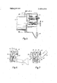
- FIG. 1 is a side elevational view of a key machine embodying the invention
- FIG. 2 is a top view of the machine of FIG. ll;
- FIG. 3 is a front view of the machine with a part of the vise broken away showing the shoulder gauge
- FIG. 4 is an enlarged sectional view on line 4-4 of FIG. 2;
- FIG. 5 is a partial sectional view on line 5-5 of FIG. 3;
- FIGS. 6 and 7 are enlarged partial views of the vise toggle clamping mechanism in the clamped and released positions, respectively.
- This key machine has a main frame 12 pivotally supporting a cutter head 13 at a pivot l4. As shown in FIG. 5, a motor 15 on head 13 drives a milling cutter 116 through gearing 17 at a reduced speed and directly drives a brush T8 to aid in removal of any burr on the completed key.
- the key machine Ill also includes a vise structure 20 including a first vise 21 and a second vise 22. These vises 211 and 22 are identical except for being mirror images of each other.
- the vise structure 20 includes a vise frame 23 which is mounted by a ball track 24 for longitudinally reciprocating movements on the main frame 12 toward and away from the milling cutter I6.
- a motor and speed reduction unit 25 is mounted in the main frame 112 and connected by a link 26 to the vise frame 23 to provide this powered longitudinal movement of the vise structure 20.
- the two vises 2i and 22 each are adapted to mount a key.
- the first vise 21 in this preferred embodiment is adapted to mount a master key 311 which already has the proper bits or notches thereon and the second vise 22 is adapted to mount a key blank 32.
- the master key 3ll is adapted to cooperate with a stylus 33 secured on the cutter head 13 to raise and lower the head 13 in ac cordance with the notches on the master key 31 so that the milling cutter 16 will cut corresponding notches on the key blank 32.
- a protective cover 34 for the cutter I16 and part of the brush 18 is shown in FIGS. 2 and 3 but shown removed in FIGS. I and 5.
- FIG. 4 generally shows the internal construction of the vise structure 20 and since the first and second vises 2ll and 22 are mirror images of each other, generally only the first vise 21 will be described.
- the first vise 21 includes movable vise jaw means 36 and a secondary jaw 39.
- the movable vise jaw means 36 includes a clamping block 37 and a separate jaw 38.
- the movable vise jaw means 36 is movably mounted on the frame 23 and in this preferred embodiment the block 37 is pivoted to frame 23 at the pivot 46.
- the secondary jaw 39 may be unitary with the vise frame 23 but in this preferred embodiment is a separate piece of hardened steel.
- the separate jaw 38 is a piece of hardened steel and these two jaws 38 and Y39 are mounted by means of pins 41 to the vise frame 123 and this provides for limited movement between the two jaws.
- a beam spring 43 lies inside the vise structure 20 and extends from the first vise to the second vise.
- the ends of the beam spring 43 cooperate with the clamping blocks in two ways.
- a coil compression spring 44 is disposed in a pocket 45 in the clamping block 37 and acts on the end of the beam spring 43..
- the clamping block 37 has a flat bearing surface 46 engaged by the end of the beam spring 43 upon slight compression of the compression spring 44.
- Mechanical advantage means 48 is mounted in the vise frame 23 and acts between the frame 23 and the central portion 49 of the beam spring 43.
- This mechanical advantage means includes a toggle mechanism 50 and a manual handle 51.
- the manual handle 5i may be considered a means to apply a force on the central portion of the beam spring 43 through the toggle mechanism 54).
- the handle Sll has clamped and released positions shown in FIGS. 6
- the clamped position of the handle 51 closes the vise jaws and the released position of the handle 51 opens the vise jaws.
- the handle 51 has a fork at one end pivoted at a close fitting hole on a pivot pin 53 and has an L-shaped extension 54.
- the pivot pin 53 is carried in the vise frame 23.
- Slide plates 55 slide in the frame 23 and are guided for vertical movement by a slot 56 therein which receives a guide 57 fixed on the frame 23.
- These slide plates 55 have an elongated slot 58 encompassing the pivot pin 53 to provide this vertical movement.
- a pivot pin 59 is carried in the slide plates 55 to move vertically therewith.
- Toggle links 60 are pivoted on the pin 59 and on a knee pivot pin 61, which is closely received in a hole in the handle 51.
- the beam spring 43 is substantially unstressed.
- the handle extension 54 engages the pivot pin 59 to provide a limit position and to make sure that the knee 61 of the toggle is fully straightened to apply the maximum mechanical advantage in movement of the handle to the beam spring 43.
- a bearing plate 62 is mounted on the pivot pin 59 and is U-shaped to embrace and act on the central portion 49 of the beam spring 43 as the knee 61 of the toggle is straightened.
- the vise structure also includes a bottom gauge which includes a bottom gauge plate 64 mounted on the pins 41.
- This gauge plate may be moved into three different lateral positions by means of a cam follower 65 and a cam 66 moved by a handle 67.
- the handle 67 may be moved to the proper position for gauging single sided, double sided or foreign car keys and this will set the proper vertically gauged positions of the keys 31 and 32 relative to the vise structure 20.
- the jaws 38 and 39 have outwardly bent lips 68 and 69 to aid in the longitudinal insertion of a key into the jaws.
- the vise structure 20 also includes a shoulder gauge 70 as shown in FIGS. 1, 2 and 3.
- the shoulder gauge 70 is shown as a lever pivoted at 71 on the vise frame 23.
- This shoulder gauge lever 70 has gauging and retracted positions shown in the right and left halves of FIG. 3, respectively. Normally, both shoulder gauges are in the same position either the gauging or the retracted positions and FIG. 3 may be considered split along a vertical center line in order to show the parts in the different positions for the retracted and gauging positions.
- Both shoulder gauges for the two vises 21 and 22 are substantially identical, merely being mirror images of each other; hence, generally the only one of the shoulder gauges for a vise 21 will be described.
- the shoulder gauge 70 is adapted to engage a shoulder 72 on the key, as shown in FIG. 1, in order to establish the proper longitudinal position of the key relative to the vise structure 20.
- the shoulder gauge lever 70 has a pin 73 engaging one end of a coil extension toggle spring 74.
- the other end of the spring 74 is mounted to an anchor 75 on the frame 23 in a position such that the axis of the spring lies on opposite sides of the lever pivot 71 for each of the gauging and retracted positions. This means that the line along which the force of the spring acts is on opposite sides of the pivot 71 for each of these two positions. and accordingly spring 74 acts as a toggle spring yieldably urging the lever 70 into each of these two positions.
- a retract lever 77 is pivoted on the vise frame 23.
- a ledge 78 is provided on the shoulder gauge in a position to be acted on by the retract lever 77.
- FIG. 3 shows the right hand slide plate 55 in the lower position in which it would be with the handle 51 in the released position.
- the handle 51 is moved downwardly to the clamped position, this raises the slide plate 55 as shown by the left hand plate in FIG. 3 which acts on the retract lever 77 in turn acting on the ledge 78 to move positively the shoulder gauge 70 from the gauging to the retracted position.
- a cover 81 shown in FIGS. 1 and 2, is shown removed in FIG. 3 to reveal the shoulder gauges 70.
- the key machine 11 may be operated by relatively unskilled personnel and in fact personnel who are relatively unpracticed in that particular machine.
- the manual handle 51 is normally in the released position shown in FIG. 7. In this condition the beam spring 43 is not stressed and the flat bearing surface 46 on the clamping blocks 37 is normally not touching the beam spring 43.
- the coil compression spring 44 provides a slight amount of resilient urging between the jaws 38 and 39. This permits a person to insert a master key, namely a key which he wishes to copy, between the jaws 38, 39. This readily may be accomplished by longitudinally inserting the key between the outwardly bent lips 68 and 69 to spread apart the jaws 38 and 39. The light force of the spring 44 easily retains the key in the desired position.
- FIG. 3 shows the two alternative positions for the shoulder gauge 70.
- slide plate 55 is lowered and retract lever 77 is raised, as on the right half of FIG. 3, but gauge lever 70 remains in the retracted position shown on the left of FIG. 3.
- the operator moves the shoulder gauge lever 70 from the retracted position shown on the left side of FIG. 3 to the gauging position shown on the right side of FIG. 3.
- the master key 31 is pushed longitudinally in until its shoulder 72 engages this shoulder gauge lever 70. This will be as shown in FIG. 1.
- the key blank 32 is inserted and put in proper gauge position in the key vise 22.
- the handle 51 may be moved downwardly from the released position of FIG. 7 to the clamped position of FIGS. 1 and 6.
- the toggle mechanism 50 straightens the knee 6] thereof to separate the pivot pins 53 and 59.
- This acts through the bearing plate 62 and forces the central portion 49 of the beam spring 43 upwardly.
- the ends of the beam spring 43 are consequently stressed upwardly.
- the light springs 44 are quickly compressed at the beginning of this movement and the ends of the beam spring 43 bear against the flat bearing surfaces 46 for positive movement of the clamping blocks 37.
- the nose of the clamping block 37 acts against the separate jaw 38 to move it toward the secondary jaw 39 and clamp the key 31 therebetween.
- the key blank 32 is also clamped in the second vise 22.
- Considerable force can be exerted on the keys especially the. blank key 32 by the milling cutter 16.
- the present vise structure 20 provides positive clamping of both keys 31 and 32 by the simple downward movement of the handle 51.
- the mechanical advantage means shown as a toggle mechanism gives a very large mechanical advantage to exert a very large clamping force on the keys and hence hold them stationary despite external forces on the keys.
- this retract mechanism is a positive linkage, not something with a yielding spring action, and thus even though the shoulder gauge lever 70 frictionally drags on the shoulder 72, such lever is positively moved out of the way.
- the motors l5 and 25 may be energized to drive the cutter l6 and to drive the vise structure forwardly and rearwardly.
- the stylus 33 will follow the master key 31 to control the up and down movements of the cutter 16 and hence the notches will be cut on the key blank 32 in accordance with the notches on the master key 311.
- the springs 44 still cause the jaws 38, 39 to lightly grip the keys, so they do not fall out, yet they may be easily removed by the operator.
- the brush 18 may be used to remove any burr remaining on the key after having been cut.
- first and second vises mounted on opposite ends of said frame
- each of said vises including movable vise jaw means and a secondary jaw
- a beam spring mounted in said frame and extending from one jaw means to the other
- each of said movable vise jaw means includes a separate vise jaw and a clamping block
- the key being clampable between the separate vise jaw and the respective secondary jaw.
- a key vise structure as set forth in claim 2 wherein 5.
- auxiliary spring means includes an auxiliary spring acting between each end of said beam spring and the respective movable vise jaw means.
- a key vise structure as set forth in claim ll including pockets in the lower surface of each said movable vise jaw means,
- a coil compression spring disposed in each pocket and acting between the respective movable jaw means and an end of said beam spring to lightly and temporarily hold in place a master key and a key blank between the movable jaw means and the respective secondary jaw for initial positioning.
- a key vise structure comprising in combination,
- force application means movable between clamped and released positions to actuate said vise between closed and opened positions
- a key shoulder gauge for said vise including a lever pivoted on said frame adjacent said vise and having gauging and retracted positions,
- overcenter spring means acting between said lever and said frame whereat the force of said spring means yieldably restrains said shoulder gauge in each of said gauging and retracted positions
- said spring means being a coil extension spring connected to said lever and to said frame in a manner such that the axis of said spring is alternatively on one side and the opposite side of said shoulder gauge lever pivot in said gauging and retract positions, respectively.
- said linkage means includes a retract lever
Landscapes
- Engineering & Computer Science (AREA)
- Mechanical Engineering (AREA)
- Gripping Jigs, Holding Jigs, And Positioning Jigs (AREA)
- Jigs For Machine Tools (AREA)
- A Measuring Device Byusing Mechanical Method (AREA)
Priority Applications (9)
| Application Number | Priority Date | Filing Date | Title |
|---|---|---|---|
| US00308285A US3834688A (en) | 1972-11-20 | 1972-11-20 | Key vise structure |
| DE2357485A DE2357485A1 (de) | 1972-11-20 | 1973-11-17 | Schluesseleinspannvorrichtung |
| JP48129302A JPS4982000A (cg-RX-API-DMAC7.html) | 1972-11-20 | 1973-11-19 | |
| CA186,193A CA993463A (en) | 1972-11-20 | 1973-11-19 | Key vise structure |
| FR7341149A FR2206996B1 (cg-RX-API-DMAC7.html) | 1972-11-20 | 1973-11-19 | |
| GB5383373A GB1404079A (en) | 1972-11-20 | 1973-11-20 | Vice assembly for a key cutting machine |
| GB182475A GB1404080A (en) | 1972-11-20 | 1973-11-20 | Vice assembly for a key cutting machine |
| IT70514/73A IT1020523B (it) | 1972-11-20 | 1973-11-30 | Dispositivo di serraggio a morsa per macchine di fabbricazione di chiavi |
| CA239,924A CA999886A (en) | 1972-11-20 | 1975-11-17 | Key vise structure |
Applications Claiming Priority (1)
| Application Number | Priority Date | Filing Date | Title |
|---|---|---|---|
| US00308285A US3834688A (en) | 1972-11-20 | 1972-11-20 | Key vise structure |
Publications (1)
| Publication Number | Publication Date |
|---|---|
| US3834688A true US3834688A (en) | 1974-09-10 |
Family
ID=23193346
Family Applications (1)
| Application Number | Title | Priority Date | Filing Date |
|---|---|---|---|
| US00308285A Expired - Lifetime US3834688A (en) | 1972-11-20 | 1972-11-20 | Key vise structure |
Country Status (7)
| Country | Link |
|---|---|
| US (1) | US3834688A (cg-RX-API-DMAC7.html) |
| JP (1) | JPS4982000A (cg-RX-API-DMAC7.html) |
| CA (1) | CA993463A (cg-RX-API-DMAC7.html) |
| DE (1) | DE2357485A1 (cg-RX-API-DMAC7.html) |
| FR (1) | FR2206996B1 (cg-RX-API-DMAC7.html) |
| GB (2) | GB1404080A (cg-RX-API-DMAC7.html) |
| IT (1) | IT1020523B (cg-RX-API-DMAC7.html) |
Cited By (1)
| Publication number | Priority date | Publication date | Assignee | Title |
|---|---|---|---|---|
| US3978764A (en) * | 1973-09-05 | 1976-09-07 | Hudson Lock, Inc. | Automatic key duplicating apparatus |
Families Citing this family (1)
| Publication number | Priority date | Publication date | Assignee | Title |
|---|---|---|---|---|
| FR2422480A2 (fr) * | 1978-04-10 | 1979-11-09 | Kis France Sa | Machine automatique a reproduire les cles plates |
Citations (4)
| Publication number | Priority date | Publication date | Assignee | Title |
|---|---|---|---|---|
| US2148668A (en) * | 1936-12-02 | 1939-02-28 | Yoskowitz Samuels | Key duplicating mechanism |
| US2329269A (en) * | 1940-04-13 | 1943-09-14 | Briggs & Stratton Corp | Key cutting and duplicating machine |
| US2422114A (en) * | 1944-03-08 | 1947-06-10 | Albert J Matter | Quick latch jig |
| US3138999A (en) * | 1962-03-27 | 1964-06-30 | Independent Lock Co | Automatic key cutter |
Family Cites Families (2)
| Publication number | Priority date | Publication date | Assignee | Title |
|---|---|---|---|---|
| FR1347246A (fr) * | 1962-11-21 | 1963-12-27 | Appareil pour distribuer et découper des ébauches de clés | |
| FR1412136A (fr) * | 1964-10-19 | 1965-09-24 | Dispositif de serrage à genouillère |
-
1972
- 1972-11-20 US US00308285A patent/US3834688A/en not_active Expired - Lifetime
-
1973
- 1973-11-17 DE DE2357485A patent/DE2357485A1/de active Pending
- 1973-11-19 FR FR7341149A patent/FR2206996B1/fr not_active Expired
- 1973-11-19 JP JP48129302A patent/JPS4982000A/ja active Pending
- 1973-11-19 CA CA186,193A patent/CA993463A/en not_active Expired
- 1973-11-20 GB GB182475A patent/GB1404080A/en not_active Expired
- 1973-11-20 GB GB5383373A patent/GB1404079A/en not_active Expired
- 1973-11-30 IT IT70514/73A patent/IT1020523B/it active
Patent Citations (4)
| Publication number | Priority date | Publication date | Assignee | Title |
|---|---|---|---|---|
| US2148668A (en) * | 1936-12-02 | 1939-02-28 | Yoskowitz Samuels | Key duplicating mechanism |
| US2329269A (en) * | 1940-04-13 | 1943-09-14 | Briggs & Stratton Corp | Key cutting and duplicating machine |
| US2422114A (en) * | 1944-03-08 | 1947-06-10 | Albert J Matter | Quick latch jig |
| US3138999A (en) * | 1962-03-27 | 1964-06-30 | Independent Lock Co | Automatic key cutter |
Cited By (1)
| Publication number | Priority date | Publication date | Assignee | Title |
|---|---|---|---|---|
| US3978764A (en) * | 1973-09-05 | 1976-09-07 | Hudson Lock, Inc. | Automatic key duplicating apparatus |
Also Published As
| Publication number | Publication date |
|---|---|
| FR2206996A1 (cg-RX-API-DMAC7.html) | 1974-06-14 |
| JPS4982000A (cg-RX-API-DMAC7.html) | 1974-08-07 |
| GB1404079A (en) | 1975-08-28 |
| FR2206996B1 (cg-RX-API-DMAC7.html) | 1977-03-11 |
| GB1404080A (en) | 1975-08-28 |
| CA993463A (en) | 1976-07-20 |
| IT1020523B (it) | 1977-12-30 |
| DE2357485A1 (de) | 1974-06-06 |
Similar Documents
| Publication | Publication Date | Title |
|---|---|---|
| US3496636A (en) | Key cutting machine with preselected depth gauging | |
| US3978764A (en) | Automatic key duplicating apparatus | |
| US2103074A (en) | Clamping device | |
| GB1560397A (en) | Key cutting machines | |
| US3633451A (en) | Key-cutting machine with coordinated positioning and cutting movements | |
| US1656295A (en) | Key-cutting machine | |
| US3430535A (en) | Key cutter | |
| US1889461A (en) | Key cutting apparatus | |
| US3834688A (en) | Key vise structure | |
| US2765848A (en) | Punches for notching blanks and tubing | |
| US2329269A (en) | Key cutting and duplicating machine | |
| US1978628A (en) | Key cutting machine | |
| US1697747A (en) | Key-duplicating machine | |
| US4562759A (en) | Universal cam for key cutting machine | |
| US4468994A (en) | Key cutting device | |
| US7300235B2 (en) | Key duplicating machine | |
| EP1486280B1 (en) | Clamping device for duplicating machines for keys of special bit type | |
| US2167008A (en) | Key duplicating machine | |
| US3001422A (en) | Machine tools | |
| US3611569A (en) | Key duplicating machine | |
| US2845985A (en) | Bending machine with swinging-wing die carrier | |
| US1439382A (en) | Key-duplicating machine | |
| US2473253A (en) | Stapling apparatus | |
| US3091157A (en) | Key duplicating machine | |
| US2168772A (en) | Work-holding vise |
Legal Events
| Date | Code | Title | Description |
|---|---|---|---|
| AS | Assignment |
Owner name: CHASE COMMERCIAL CORPORATION, 55 E. MONROE, STE. 3 Free format text: SECURITY INTEREST;ASSIGNOR:WINSTON INDUSTRIES, INC.;REEL/FRAME:003973/0076 Effective date: 19820331 |
|
| AS | Assignment |
Owner name: AMERICAN CONSUMER PRODUCTS INC., 5777 GRANT AVENUE Free format text: ASSIGNMENT OF ASSIGNORS INTEREST.;ASSIGNOR:COLE CONSUMER PRODUCTS, INC., A CORP OF DE;REEL/FRAME:004202/0655 Effective date: 19821201 |