US3828811A - Valve assembly - Google Patents
Valve assembly Download PDFInfo
- Publication number
- US3828811A US3828811A US36560073A US3828811A US 3828811 A US3828811 A US 3828811A US 36560073 A US36560073 A US 36560073A US 3828811 A US3828811 A US 3828811A
- Authority
- US
- United States
- Prior art keywords
- passageway
- valve piece
- surface portion
- housing
- valve
- Prior art date
- Legal status (The legal status is an assumption and is not a legal conclusion. Google has not performed a legal analysis and makes no representation as to the accuracy of the status listed.)
- Expired - Lifetime
Links
- 238000007789 sealing Methods 0.000 claims abstract description 12
- 238000004891 communication Methods 0.000 claims description 6
- 238000013270 controlled release Methods 0.000 claims description 4
- 230000003467 diminishing effect Effects 0.000 claims description 2
- 238000005259 measurement Methods 0.000 description 3
- 238000010276 construction Methods 0.000 description 2
- 238000012423 maintenance Methods 0.000 description 2
- 239000002184 metal Substances 0.000 description 2
- 230000002411 adverse Effects 0.000 description 1
- 230000000712 assembly Effects 0.000 description 1
- 238000000429 assembly Methods 0.000 description 1
- 230000036772 blood pressure Effects 0.000 description 1
- 230000003292 diminished effect Effects 0.000 description 1
- 238000004519 manufacturing process Methods 0.000 description 1
- 230000013011 mating Effects 0.000 description 1
- 238000005065 mining Methods 0.000 description 1
- 230000002093 peripheral effect Effects 0.000 description 1
- 230000002040 relaxant effect Effects 0.000 description 1
- 230000000717 retained effect Effects 0.000 description 1
Images

Classifications
-
- F—MECHANICAL ENGINEERING; LIGHTING; HEATING; WEAPONS; BLASTING
- F16—ENGINEERING ELEMENTS AND UNITS; GENERAL MEASURES FOR PRODUCING AND MAINTAINING EFFECTIVE FUNCTIONING OF MACHINES OR INSTALLATIONS; THERMAL INSULATION IN GENERAL
- F16K—VALVES; TAPS; COCKS; ACTUATING-FLOATS; DEVICES FOR VENTING OR AERATING
- F16K37/00—Special means in or on valves or other cut-off apparatus for indicating or recording operation thereof, or for enabling an alarm to be given
-
- A—HUMAN NECESSITIES
- A61—MEDICAL OR VETERINARY SCIENCE; HYGIENE
- A61B—DIAGNOSIS; SURGERY; IDENTIFICATION
- A61B5/00—Measuring for diagnostic purposes; Identification of persons
- A61B5/02—Detecting, measuring or recording for evaluating the cardiovascular system, e.g. pulse, heart rate, blood pressure or blood flow
- A61B5/021—Measuring pressure in heart or blood vessels
- A61B5/022—Measuring pressure in heart or blood vessels by applying pressure to close blood vessels, e.g. against the skin; Ophthalmodynamometers
- A61B5/0235—Valves specially adapted therefor
-
- F—MECHANICAL ENGINEERING; LIGHTING; HEATING; WEAPONS; BLASTING
- F16—ENGINEERING ELEMENTS AND UNITS; GENERAL MEASURES FOR PRODUCING AND MAINTAINING EFFECTIVE FUNCTIONING OF MACHINES OR INSTALLATIONS; THERMAL INSULATION IN GENERAL
- F16K—VALVES; TAPS; COCKS; ACTUATING-FLOATS; DEVICES FOR VENTING OR AERATING
- F16K3/00—Gate valves or sliding valves, i.e. cut-off apparatus with closing members having a sliding movement along the seat for opening and closing
- F16K3/30—Details
- F16K3/34—Arrangements for modifying the way in which the rate of flow varies during the actuation of the valve
-
- Y—GENERAL TAGGING OF NEW TECHNOLOGICAL DEVELOPMENTS; GENERAL TAGGING OF CROSS-SECTIONAL TECHNOLOGIES SPANNING OVER SEVERAL SECTIONS OF THE IPC; TECHNICAL SUBJECTS COVERED BY FORMER USPC CROSS-REFERENCE ART COLLECTIONS [XRACs] AND DIGESTS
- Y10—TECHNICAL SUBJECTS COVERED BY FORMER USPC
- Y10T—TECHNICAL SUBJECTS COVERED BY FORMER US CLASSIFICATION
- Y10T137/00—Fluid handling
- Y10T137/8158—With indicator, register, recorder, alarm or inspection means
- Y10T137/8225—Position or extent of motion indicator
- Y10T137/8275—Indicator element rigidly carried by the movable element whose position is indicated
Definitions
- a valve assembly is provided for use in a sphygmomanometer and includes a housing provided with an elongated first air passageway and a second air passageway having one end thereof communicating with the first passageway and the second end thereof terminating at an exterior surface portion of the housing.
- a valve piece overlies the housing exterior surface and is mounted thereon for manual rotation through a predetermined sector, delimited by first and second positions of adjustment. Rotation of the valve piece is about an axis disposed transverse of the exterior surface portion.
- the valve piece is provided with a passageway which interconnects first and second surface portions.
- the valve piece first surface portion is in sliding sealing engagement with the housing surface portion.
- One of the engaging surface portions is provided with an elongated groove extending from the end of the passageway terminating at the one engaging surface portion. The cross-sectional size of the groove diminishes uniformly from a maximum at the passageway end to zero at the distal end of the groove.
- the second passageway has one end thereof terminating at an exterior surface portion of the housing.
- a manually adjustable valve piece overlies the exterior surface portion and is adapted to be moved through a predetermined sector about an axis transversely disposed with respect to the housing exterior surface portion.
- the valve piece is provided with first and second surface portions which are interconnected by a passageway.
- the valve piece first surface portion is maintained in sliding, sealing engagement with the housing exterior surface portion.
- An elongated groove is formed in one of the engaging surfaces and extends from the end of passageway terminating at the surface portion.
- the crosssectional size of the groove diminishes uniformly from a maximum at the passageway end to zero at the distal end of the groove.
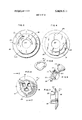
- FIGS. 1 and 2 are perspective views, top and bottom, respectively, of one form of a valve assembly adapted for use in a sphygmomanometer;
- FIG. 3 is an enlarged fragmentary side elevational view of the assembly of FIG. 1 with portions thereof in vertical section;
- FIG. 3A is an enlarged fragmentary vertical sectional view of a portion of FIG. 3;
- FIG. 4 is an enlarged view of the valve piece'showing the inner or first surface portion thereof;
- FIG. 5 is similar to FIG. 4 but showing the outer or second surface of the valve piece
- FIG. 6 is an enlarged top plan view of the valve pieceretaining member shown in FIG. 2;
- FIG. 7 is an enlarged side elevational view of the member of FIG. 6 and with a portion thereof in vertical section;
- FIG. 8 is a perspective view of one form of a biasing spring used to retain the valve piece in a sliding sealing engagement with an exterior surface portion of the housing as seen in FIG. 3;
- FIG. 9 is a fragmentary perspective view of a modified form of the valve assembly.
- valve assembly 10 which is adapted for use in a sphygmomanometer, not shown.
- the assembly includes a housing 11, preferably molded of metal, plastic or the like; a gauge 12 mounted on the housing; a manually adjustable valve 13 carried on the housing; and a squeezable bulb 14 used to inflate the cuff, not shown, which is adapted to be wrapped about a limb at the time the patients blood pressure is to be measured.
- housing 11 is provided with an elongated first passageway 15, one end of which is engaged by a connector 14a carried by the discharge end of the bulb.
- the connector 14a includes a one-way valve 16 permitting air flow only in one direction into the passageway 15, and a filter piece 17 disposed within the passageway.
- a second passageway 18 is formed in housing 11 and has one end thereof communicating with passageway 15 and the other end terminating at an exterior surface portion 11a of the housing.
- a third passageway 20 is provided which may have a flexible portion. Passageway 20 has one end thereof communicating with the opposite end of passageway 15. The second end of passageway 20 terminates at a fourth passageway 21 provided within the housing.
- a hose connector 22 is affixed to one end of passageway 21 and is adapted to accommodate a flexible hose 23, see FIG. 3, which leads to the cuff, not shown.
- the opposite end of passageway 21 communicates with an end of a bellows-type unit 24 which is a component of gauge 12.
- the unit 24 permits a rotatably mounted indicator 12a to be responsive to the air pressure generated within passageway 21 and thus, rotate relative to an exposed calibrated dial 12b mounted on the exterior of the housing 11, see FIG. 1.
- the unit 24 is provided with a narrow opening 25, which communicates with passageway 21, see FIGS. 3 and 3A.
- a dampening element 26 Loosely positioned within opening 25 is a dampening element 26, which in the illustrated embodiment has an elongated rod or wirelike central portion 26a having a diameter less than the diameter of opening 25.
- the opposite ends 26b of the element 26 are swagged or enlarged so as to prevent the element from becoming disassembled from the opening when pressured air flows through the opening 25. Because of the restrictive character of the element 26 within the opening 25, the pulsating flow of air through the bellows unit 24 is eliminated thus preventing abrupt, oscillating movement of the indicator 12a, when the cuff is being inflated by manual squeezing of the bulb 14.
- the indicator 12a may be made more sensitive thereby enabling more accurate readings to be taken when the sphygmomanometer is being used.
- the valve 13, as seen in FIGS. 2 and 3, is located adjacent the forward end of the housing and is in close proximity to the bulb connector 14a.
- the valve 13 includes a disc-shaped valve piece 27 having a flat inner surface portion 27a which is substantially coincident to the housing exterior surface portion 11a.
- the surface portions 11a and 270 are contoured so that a sliding sealing engagement is maintained between them in a manner to be hereinafter described.
- the outer surface portion 27b of the valve piece 27 is substantially flat and the two surface portions 27a and b are interconnected by a large, centrally disposed opening 27c and a small opening 27d offset from opening 27c.
- the two surface portions are delimited by an annular rim 28.
- the outer peripheral surface of the rim may be knurled or roughened so as to facilitate manual rotating of the valve piece.
- the outer exposed surface of the rim 28 may be provided with calibrated indicia I.
- surface portion 27a of the valve piece is provided with an elongated arcuate groove 30 which has one end thereof terminating at opening 27d.
- the depth or cross-sectional size of the groove 30 diminishes uniformly from a maximum at opening 27d to zero at the distal end.
- the center of curvature of the groove is preferably coincident to the axis of opening 270.
- groove 30 being formed in surface portion 27a, it may in certain instances be formed in the housing exterior surface portion 11a, with the end of the groove having the greatest depth or cross-section terminating at the second passageway 18 formed in the housing 11.
- the valve piece 27 is adapted to be manually moved only through a predetermined sector (e.g. approximately l80).
- a predetermined sector e.g. approximately l80.
- the valve piece When the valve piece is disposed at one terminal position of adjustment, the small opening 27d is aligned with the end of passageway 18 thereby causing any air pressure within passageway 21 to be rapidly exhausted to the atmosphere and resulting in relaxing of the cuff encompassing the limb.
- the valve piece assumes the opposite terminal position of adjustment, the end of passageway 18 is completely closed off by the valve piece surface portion 27a. When this latter condition occurs, the cuff-inflating air pressure within passageway 21 is not diminished. The rate at which the air pressure within passageway 21 is exhausted to the atmosphere will depend upon the setting of the valve piece between the two terminal positions, aforedescribed.
- the valve piece 27 is retained in assembled relation on the housing exterior by a retainer member 31, see FIGS. 6 and 7.
- the retainer member has an enlarged annular end section 32 which is sized to substantially coincide with the area delimited by the rim 28 of the valve piece 27, see FIG. 3.
- Extending transversely from the concealed surface of end section 32 is a shank section 33 which slidably fits in the enlarged opening 270 formed in the valve piece.
- the end of the shank section abuts the exterior surface portion 11a of the housing.
- the surface portion 11a may be provided with a slight depression which is adapted to accommodate the shank section end.
- Symmetrically arranged about the axis of the member 31 are a plurality of elongated openings 34 which are adapted to receive screw fasteners 35.
- the fasteners are threaded into suitable openings 36 formed in the housing exterior and secure the member in a fixed position on the housing.
- the length of the shank section 33 is such that the concealed surface 32a of the end section 32 will be spaced a predetermined distance from the housing surface portion 110.
- a first stop element 37 which constitutes a segment of a circle; in the illustrated embodiment the segment is approximately
- the element 37 projects into the space S formed between the concealed surface 32a of the end section 32 and the outer surface portion 27b of the valve piece 27.
- the stop element 37 is adapted to engage a complemental stop element 38 formed on surface portion 27b of the valve piece.
- the stop element 38 constitutes a segment of a circle of approximately 90.
- the two stop elements 37 and 38 restrict the relative movement of the valve piece 27 to within a sector of approximately As aforementioned, the surface portion 27a of the valve piece 27 is maintained in a sliding sealing engagement with the exterior surface portion 11a of the housing 11.
- a ring-type spring 40 see FIG. 8, may be utilized.
- the inner diameter of the spring is such that it will readily encompass the shank section 33 and the stop element 37 of the member 31.
- the spring 40 may be formed of a suitable metal and have an undulating configuration.
- an elongated arcuate groove 41 may be formed in surface portion 27b, see FIG. 5. One end of the groove terminates at the opening 27d.
- the groove is preferably of uniform cross-section throughout.
- the exposed surface of member 31 is provided with an embossed pointershaped indicator 32b.
- the indicator 32b may be debossed or painted on the surface, or in some instance may be eliminated.
- the indicator 32b is adapted to cooperate with the indicia I provided on the upper surface of the valve piece rim 28 to enable 0e to readily observe the relative position of the small opening 27d of the valve piece with respect to the end of passageway 18.
- the housing 11 may be formed into two mating sections 11b and 11c which may be separated when desired so as to expose various components disposed within the housing interior.
- the configuration of the gauge and valve components and the housing- may be varied from that shown without departing from the scope of the invention.
- valve assembly 110 In FIG. 9 a modified form of valve assembly 110 is shown wherein the housing 111 includes first and second passageways arranged in a manner as seen in FIG. 3.
- the hose to the cuff, not shown, is secured to a connector 122 which in turn is mounted on the exterior of the housing 111 opposite the squeezable bulb 114.
- Mounted on housing 111 is the valve 113 which embodies the same components as described with regard to valve 13.
- the gauge 12 is a separate unit and is not integral with respect to the housing 111. Aside from this structural difference, the valve assemblies and 110 operate in similar manner.
- valve assembly which is of compact sturdy construction, easy to manipulate, permits accurate control of the valve to facilitate taking measurements, .and dampens movement of the gauge indicator when there is pulsating air flow through portions of the assembly.
- a valve assembly for use in a sphygmomanometer to permit controlled release of pneumatic pressure accumulated within the sphygmomanometer, said assembly comprising a housing provided with a first air passageway in which a predetermined amount of pneumatic pressure is accumulated, said first air passageway being in communication with a pneumatically responsive pressure gauge, and a second air passageway having one end thereof communicating with said first passageway and a second end terminating at an exterior surface portion of said housing; a valve piece rotatably mounted on said housing surface portion for controlled manual adjustment through a predetermined sector about an axis disposed substantially transverse to said housing surface portion, said valve piece having first and second surface portions interconnected by a passageway offset from said axis, the end of the latter passageway terminating at the second surface portion being in continuous communication with the exterior of the sphygmomanometer, said valve piece first surface portion being in sliding, sealing engagement with said housing surface portion, one engaging surface portion being provided with an elongated arcuate groove extending from the passageway end
- valve piece-retaining means includes an exposed outer section overlying in spaced relation said valve piece second surface portion, an inner section projecting from said outer section and slidably extending through said valve piece opening and being secured to said housing exterior surface portion, and biasing means interposed and resiliently engaging said outer section and said valve piece second surface portion and urging said valve piece first surface portion into sliding sealing engagement with said housing exterior surface portion.
- valve assembly of claim 2 wherein said valve piece second surface portion is provided. with a first stop means spaced from the passageway of said valve piece; and said valve piece-retaining means is provided with complemental second stop means, said first and second stop means cooperating with one another to restrict movement of said valve piece to within said predetermined sector.
- valve assembly of claim 2 wherein the second surface portion of said valve piece is provided with said elongated arcuate groove.
- valve assembly of claim 4 wherein the outer periphery of said valve piece second surface portion is provided with annularly spaced first indicia in partially encircling relation with respect to said valve piece axis, and the outer section of said valve piece-retaining means is provided with a complemental second indicia, the relative positions of said first and second indicia corresponding to the relative position of said valve piece passageway with respect to the second end of the second air passageway formed in said housing.
- valve assembly of claim 5 wherein the first indicia of said valve piece is disposed on a raised rim encircling the second surface portion of said valve piece.
- valve assembly of claim 1 wherein the exterior surface portion of said housing and the first surface portion of said valve piece are flat and substantially coincident.
- a valve assembly for use in a sphygmomanometer comprising a housing provided with an elongated first air passageway, a second air passageway having one end thereof communicating with said first passageway and a second end thereof terminating at an exterior surface portion of 'said'housing, and a third air passageway having one end thereof communicating with said first passageway and spaced from said second passageway; gauge means connected to the opposite end of said third air passageway, said gauge means including a movable element responsive to the air pressure within said first passageway; means adjustably mounted within said third passageway for dampening pulsating air flow therethrough; and manually adjustable valve means mounted on said housing exterior surface portion, said valve means including a valve piece having an inner surface portion is sliding, sealing engagement with the housing exterior surface portion, said valve piece being 9.
- the means adjustably mounted within the housing third passageway includes an elongated rod, the exterior of which cooperates with the wall of said third passageway to form a restricted passage substantially smaller in crosssectional size than said
Landscapes
- Health & Medical Sciences (AREA)
- Engineering & Computer Science (AREA)
- General Engineering & Computer Science (AREA)
- Life Sciences & Earth Sciences (AREA)
- Mechanical Engineering (AREA)
- Vascular Medicine (AREA)
- Cardiology (AREA)
- Biophysics (AREA)
- Medical Informatics (AREA)
- Physiology (AREA)
- Ophthalmology & Optometry (AREA)
- Pathology (AREA)
- Biomedical Technology (AREA)
- Heart & Thoracic Surgery (AREA)
- Physics & Mathematics (AREA)
- Molecular Biology (AREA)
- Surgery (AREA)
- Animal Behavior & Ethology (AREA)
- General Health & Medical Sciences (AREA)
- Public Health (AREA)
- Veterinary Medicine (AREA)
- Measuring Pulse, Heart Rate, Blood Pressure Or Blood Flow (AREA)
- Sliding Valves (AREA)
Priority Applications (4)
| Application Number | Priority Date | Filing Date | Title |
|---|---|---|---|
| US36560073 US3828811A (en) | 1973-05-31 | 1973-05-31 | Valve assembly |
| AU69504/74A AU473361B2 (en) | 1973-05-31 | 1974-05-29 | A valve assembly |
| DE19742426351 DE2426351A1 (de) | 1973-05-31 | 1974-05-30 | Ventileinheit |
| JP6141074A JPS5021591A (ja) | 1973-05-31 | 1974-05-30 |
Applications Claiming Priority (1)
| Application Number | Priority Date | Filing Date | Title |
|---|---|---|---|
| US36560073 US3828811A (en) | 1973-05-31 | 1973-05-31 | Valve assembly |
Publications (1)
| Publication Number | Publication Date |
|---|---|
| US3828811A true US3828811A (en) | 1974-08-13 |
Family
ID=23439538
Family Applications (1)
| Application Number | Title | Priority Date | Filing Date |
|---|---|---|---|
| US36560073 Expired - Lifetime US3828811A (en) | 1973-05-31 | 1973-05-31 | Valve assembly |
Country Status (4)
| Country | Link |
|---|---|
| US (1) | US3828811A (ja) |
| JP (1) | JPS5021591A (ja) |
| AU (1) | AU473361B2 (ja) |
| DE (1) | DE2426351A1 (ja) |
Cited By (7)
| Publication number | Priority date | Publication date | Assignee | Title |
|---|---|---|---|---|
| US3954099A (en) * | 1974-02-08 | 1976-05-04 | Propper Manufacturing Company, Inc. | Sphygmomanometer |
| US4050311A (en) * | 1976-01-21 | 1977-09-27 | John Meredith Leach | Sphygmomanometer |
| US4248242A (en) * | 1978-01-20 | 1981-02-03 | Tamm Ulf S H | Occlusive sphygmomanometer for the measuring of the arterial blood pressure |
| USD327324S (en) | 1989-09-30 | 1992-06-23 | Terumo Kabushiki Kaisha | Deflation valve for sphygmomanometer |
| US20190316690A1 (en) * | 2016-11-08 | 2019-10-17 | Mueller International, Llc | Valve body with identification tab |
| CN114110195A (zh) * | 2021-12-24 | 2022-03-01 | 北京华源泰盟节能设备有限公司 | 一种可精确调节流量的节流阀门 |
| US20240245310A1 (en) * | 2023-01-20 | 2024-07-25 | Shenzhen Jamr Technology Co., Ltd. | Air control mechanism and sphygmomanometer |
-
1973
- 1973-05-31 US US36560073 patent/US3828811A/en not_active Expired - Lifetime
-
1974
- 1974-05-29 AU AU69504/74A patent/AU473361B2/en not_active Expired
- 1974-05-30 JP JP6141074A patent/JPS5021591A/ja active Pending
- 1974-05-30 DE DE19742426351 patent/DE2426351A1/de active Pending
Cited By (11)
| Publication number | Priority date | Publication date | Assignee | Title |
|---|---|---|---|---|
| US3954099A (en) * | 1974-02-08 | 1976-05-04 | Propper Manufacturing Company, Inc. | Sphygmomanometer |
| US4050311A (en) * | 1976-01-21 | 1977-09-27 | John Meredith Leach | Sphygmomanometer |
| US4248242A (en) * | 1978-01-20 | 1981-02-03 | Tamm Ulf S H | Occlusive sphygmomanometer for the measuring of the arterial blood pressure |
| USD327324S (en) | 1989-09-30 | 1992-06-23 | Terumo Kabushiki Kaisha | Deflation valve for sphygmomanometer |
| US20190316690A1 (en) * | 2016-11-08 | 2019-10-17 | Mueller International, Llc | Valve body with identification tab |
| US11384845B2 (en) * | 2016-11-08 | 2022-07-12 | Mueller International, Llc | Valve body with identification tab |
| US11959558B2 (en) | 2016-11-08 | 2024-04-16 | Mueller International, Llc | Valve body with bypass |
| CN114110195A (zh) * | 2021-12-24 | 2022-03-01 | 北京华源泰盟节能设备有限公司 | 一种可精确调节流量的节流阀门 |
| CN114110195B (zh) * | 2021-12-24 | 2023-09-12 | 北京华源泰盟节能设备有限公司 | 一种可精确调节流量的节流阀门 |
| US20240245310A1 (en) * | 2023-01-20 | 2024-07-25 | Shenzhen Jamr Technology Co., Ltd. | Air control mechanism and sphygmomanometer |
| US12575747B2 (en) * | 2023-01-20 | 2026-03-17 | Shenzhen Jamr Technology Co., Ltd. | Air control mechanism and sphygmomanometer |
Also Published As
| Publication number | Publication date |
|---|---|
| AU6950474A (en) | 1975-12-04 |
| AU473361B2 (en) | 1976-06-17 |
| DE2426351A1 (de) | 1974-12-19 |
| JPS5021591A (ja) | 1975-03-07 |
Similar Documents
| Publication | Publication Date | Title |
|---|---|---|
| US4690171A (en) | Valve assembly for a sphygmomanometer | |
| US3504663A (en) | Air flow control | |
| US5557049A (en) | Disposable manometer for use with a CPR bag | |
| US4730635A (en) | Valve and method | |
| US3828811A (en) | Valve assembly | |
| US2819728A (en) | Flow regulator | |
| GB2348941A (en) | Automatic pressure regulating valve | |
| US4552153A (en) | Pressure gauge | |
| US5137024A (en) | Gas flow valve and sphygmomanometer air-feeding/discharging apparatus using the same | |
| US4356820A (en) | Heat reclaimer for demand regulator | |
| US8652056B2 (en) | Deflation control valve | |
| US4072171A (en) | Pressure control valve for a sphygmomanometer | |
| US3613668A (en) | Sphygmomanometer with built-in timer | |
| US3978878A (en) | Resilient supply and exhaust valve | |
| US5143077A (en) | Constant-rate discharge valve, and electronic automatic sphygmomanometer using same | |
| US4798203A (en) | Portable emergency breathing apparatus | |
| US4708169A (en) | Pneumatic pressure gauge | |
| US2624334A (en) | Blood pressure taking device | |
| US4037587A (en) | Valve assembly for a sphygmomanometer | |
| US2934061A (en) | Sphygmomanometers | |
| US3237633A (en) | Pneumatic transducers | |
| US3823707A (en) | Retaining means for sphygmomanometer valve control head | |
| ES316645A1 (es) | Un dispositivo valvular para control de fluido | |
| US4098291A (en) | Pressure relief valve | |
| US3448961A (en) | Valve |
Legal Events
| Date | Code | Title | Description |
|---|---|---|---|
| AS | Assignment |
Owner name: CRITIKON, INC., 1410 N. WESTSHORE BLVD., TAMPA, FL Free format text: ASSIGNMENT OF ASSIGNORS INTEREST.;ASSIGNOR:CREST TOOL CORPORATION A CORP OF IL;REEL/FRAME:004289/0365 Effective date: 19820816 Owner name: CRITIKON, INC.,FLORIDA Free format text: ASSIGNMENT OF ASSIGNORS INTEREST;ASSIGNOR:CREST TOOL CORPORATION A CORP OF IL;REEL/FRAME:004289/0365 Effective date: 19820816 |
|
| STCF | Information on status: patent grant |
Free format text: PATENTED FILE - (OLD CASE ADDED FOR FILE TRACKING PURPOSES) |