US381429A - Wagon-step - Google Patents
Wagon-step Download PDFInfo
- Publication number
- US381429A US381429A US381429DA US381429A US 381429 A US381429 A US 381429A US 381429D A US381429D A US 381429DA US 381429 A US381429 A US 381429A
- Authority
- US
- United States
- Prior art keywords
- supports
- wagon
- steps
- side pieces
- secured
- Prior art date
- Legal status (The legal status is an assumption and is not a legal conclusion. Google has not performed a legal analysis and makes no representation as to the accuracy of the status listed.)
- Expired - Lifetime
Links
- 239000002184 metal Substances 0.000 description 8
- 238000010276 construction Methods 0.000 description 6
- 210000002832 Shoulder Anatomy 0.000 description 4
- 230000001174 ascending Effects 0.000 description 2
- 230000000875 corresponding Effects 0.000 description 2
- 230000004048 modification Effects 0.000 description 2
- 238000006011 modification reaction Methods 0.000 description 2
- 230000036633 rest Effects 0.000 description 2
- 239000007787 solid Substances 0.000 description 2
Images

Classifications
-
- E—FIXED CONSTRUCTIONS
- E06—DOORS, WINDOWS, SHUTTERS, OR ROLLER BLINDS IN GENERAL; LADDERS
- E06C—LADDERS
- E06C1/00—Ladders in general
- E06C1/52—Ladders in general with non-rigid longitudinal members
Description
(No Model. 2 Sheets-Sheet 1.
E. SCOTT.
WAGON STEP.
N0. 381,429. Patented Apr. 17 1888.
I J&
INT/E OR.
guaw, 6 0&5? w
torne s. FhokrLithognphqr, Washirgm D. u
4 2 SheetsSheet 2. E. SCOTT.
WAGON STEP.
(No Model.)
No. 381,429, Patented Apr. 17, 1888.
- WITNESSES, fi. 06.
lNirs STATES PATENT ()rrrcs.
EDYVARD SCOTT, OF OEDARVILLE, ARKANSAS.
WAGON-STEP.
SPECIFICATION forming part of Letters Patent No. 381,429, dated April 17, 1888. Application filed December 27, 1887. Serial No. 259,050. (No model.)
To all whom it may concern.-
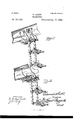
Be it known that l', EDWARD Soorr, a citizen of the United States, and a resident of Gedarville, in the county of Crawford and State of Arkansas, have invented certain new and useful Improvements in XVagonSteps; and I do hereby declare that the following is a full, clear, and exact description of the invention, which will enable others skilled in the art to which it appertains to make and use the same, reference being had to the accompanying drawings, which form a part of this specification, and in which- Figure 1 is a perspective view of my new and improved detachable folding wagon-steps, showing the same secured in operative position to the rear end of a wagon, and unfolded for use. Fig. 2shows the steps folded up and detached from the wagon. Fig. 3 is a side view of one of the middle side supports. Fig. 4 is a perspective view of one of the steps with its side pieces; and Figs. 5 and 6 are perspective views showing modifications of the upper supports designed to be used in securing the steps to the sides of wagons which have a step or board secured to the side of the wagon-bed between the wheels.
The same numerals ofreferenceindicate corresponding parts in all the figures.
Myinvention consists in a new and improved detachable folding step or steps, which is designed to be secured, removably, to the end or side of a wagon, as required, which can be readily unfolded for use and folded up when not in use, and which can be detached and removed entirely from the wagon in a moment when the wagon is not to be used; and my invention will be hereinafter fully described and claimed.
Referring to the several parts by their designating-numerals, 1 indicates the body of a wagon, to which myinvention is shown as applied, 2 being the rear end board of the same, and 3 3 the sides thereof.
4. 4 indicate the top side pieces or supports of the folding steps, the said pieces being formed each of a single strip of metal, which .is bent or curved at its upper end to form a hook, 5, of such size and curvature as to adapt it to hook readily and hold securely over the top of the rear end of a wagon to which my in- .lower ends of the upper supports.
vention is applied. These top supports, 4 4., are connected near their upper hooked ends by the transverse rod 6, and are also connected near their lower ends by a transverse pivotbolt, 7, upon which is mounted a cylinder or sleeve, 8, the ends of which bear against the inner side of the upper ends of the middle supports, 10 10, and prevent the said upper ends from drawing in toward each other.- These middle supports, 10 10, are of the-shape shown in the side view, Fig. 8 of the drawings, being formed each of a single strip of metal, of suitable size and thickness, and are pivotally mounted at their upper ends upon the transverse pivot-bolt 7, which connects the The ends of the sleeve 8 upon this pivot-bolt 7 bear against the inner sides of the upper ends of the middle supports and prevent the said ends from drawing in toward each other, as before stated. The upper rear ends of these middle supports are notched at 11, and when the lower supports are unfolded out for use these upper rear notched or shouldered ends will bear against projections or bolts 12 12, which are preferably formed on the inner side of the lower ends of the upper supports above and a little back of the pivot-bolt 7, and it will be seen that these projections will hold the mid- (He supports firmly and rigidly in their unfolded position in line with the upper supports.
The upper ends of the middle supports are formed on their forward sides or edges, below their upper pivotal points, with the recesses 13 13, which, when the middle supports, with their step, are folded up within the upper supports, will come in contact with the stops or projections 12 12, and thus hold the supports in their folded position.
14 indicates the upper step,'15 the middle step, and 16 the lower step, each of the said steps being formed alike. Each step is formed with side pieces,17 17, and the tread 18. These side pieces are pivoted near their rear projecting ends upon the pivot-bolts 7, the upper step having the rear ends of its side pieces fitting in between the lower ends of the upper sup ports and the upper ends of the middle supports pivoted upon the bolt 7, the upper rear edges of the said side pieces being beveled or inclined downward, as clearly shown in Fig.
the step lighter and increases the attractiveness of its appearance. The tread of the steps can of course be formed in any desired pattern,the one shown in Fig. 4 merely illustrating one neat and desirable form of pattern. The upper edges of the side pieces of the steps are formed, in front of the pivotal point of the step, with the edge recesses, 20, which, when the step is folded up and back, will bear against the projections 12 12 and serve to hold the step in position. The three steps are formed precisely alike, except that the lower step is formed a little longer than the middle one and the middle stepa little longer than the upper, for convenience in ascending and descending.
The lower ends of the middle supports are formed on their inner sides with the projections 12 12, like those of the upper supports, and their lower ends are connected by the transverse pivot-bolt 7. The upper ends of the lower supports, 23, are pivoted upon this pivot-bolt in the lower end of the middle supports, while the rear ends of the side pieces of the middle. step are pivotally mounted upon the bolt 7 between the lower ends of the middle supports and the upper ends of the lower supports.
The lower supports are formed precisely like the middle supports, and a more detailed description of them is therefore unnecessary. The lower step is pivotally secured near the rear ends of its side pieces upon the transverse pivot-bolt 7, which extends through the lower ends of the lower support, and is held rigidly in its unfolded position by the stops 12 12, as shown, the sleeve 8 being here dispensed with, as the solid lower step will prevent the lower ends of the side pieces from drawing together.
These new and improved folding steps are secured in operative position to the rear end of a wagon, as shownin Fig. 1 of the drawings, the hooks at the upper ends of the upper supports hooking over the rear end-board of the wagon when the step is unfolded out, as shown in the said view, and can be conveniently ascended and descended in entering or leaving the wagon. When the passengers have ascended the steps and entered the,wagon,the steps and supports are swung up and folded into each other, as shown in Fig. 2, thelower supports being shorter than the middle ones, so as to fold up within the same, while the middle supports are in turn slightly shorter than the upper ones, so as to fold up into the same. When the steps are thus folded up, when they will be out of the way and occupy a small space, they are held up in this folded position by means of a small book or snap, 24,
which is attached to the small cross-rod 6 at the upper end of the top supports, and which is engaged with the pivot-bolt 7 ,which passes through the lower ends of the middle supports and the upper ends of the lower supports. The steps are unfolded when the party wish to descend from the wagon and swung down into operative position, as shown in Fig. 1, and when the wagon is placed in the stable the entire steps can be detached from the wagon by freeing the hooked ends 5 of the upper supports from the upper edge of the rear endboard thereof.
When it is desired to attach the steps to the side of a wagon'which has the usual board, 25, between the wheels at the side of the wagonbed, the top supports, 4 4, are replaced by those shown in Figs. 5 and 6 of the drawings.
In Fig. 5 the wagon has the wooden step or board 25 at its side between the wheels. 26 26 indicate upper supports which are used in this view, eachof the said supports or side pieces being formed of a single strip of metal of the requisite size, the said pieces being beveled-at their upper ends to fit against the side of the wagon-bed, where they are secured to the side of the wagon by staples 27 2?,passing through the holes 28 28 in their upper ends, about six inches above the board 25. The lower ends of these upper supports are formed with the slanting slots29 29, and are connected and braced together a little above these slots by the transverse rod 30, as shown. The lower ends of the upper supports rest upon or a little below the outer edge of the board 25, and the folding steps are secured to these upper supports by putting the pivot-bolt 7, which passes. through the upper ends of the middle supports, in the slots 29 29 in the lower ends of the said supports 26, and when the steps are unfolded out the notched upper rear ends of the middle supports will bear against the transverse rod 30, and the steps be thus held in position with the supports at the proper inclination. When the steps are folded up, the lower end of the middle supports will fest against the side of the wagon, near the top thereof, above the wooden step 25, and is caught and held in this folded-up position by a snap-hook, 31, as shown, this snap-hook being attached to the upper part of the side of the wagon. V
In place of the top supports above described I can use those shown in Fig. 6 of the drawings, in which construction the top supports are formed each of a single strip or piece of metal, 32, of sufficient length and size. The outer end of each of the said supports is bent to form a downwardly-extending loop or hook, 33, and the outer portion of the said supports rests upon the board 25 and is there secured by the bolts 34. The middle part of the supports back of the board is then bent or inclined downward and then extends straight back, the object of this drop or bend at the centerbeing to bring the rear ends of the sup- IIO ports beneath the lower edge of the wagon-bed, where the rear ends of the supports are bolted to the wagon-bed, or otherwise secured. The outer ends of the supports 32 are formed on their outer sides, just back of their hooked ends, with the stops or projections 35 35. The object of forming these shoulders or stops 35 on the outer side of the supports is to bring the supports nearer together on the wooden board. The upper ends of the middle supports are connected to the outer ends of these hooked upper supports by slipping the pivotbolt 7, which passes through the upper end of the middle supports, in the hooks on the outer ends of the fixed upper supports, when the steps can be unfolded, when the notched rear upper ends of the middle supports will bear against the shoulders or stops 35 35, and the middle supports will be held firmly in line at the proper inclination. When the steps are folded up, they are secured in that position by a snap-hook, 36, similar to the hook 31.
From the foregoing description, taken in connection with the accompanying drawings, the construction, operation, and great ad vantage of my invention will be readily seen. It will be seen that my new and improved detachable folding steps for wagons, &c., are simple and strong in construction, and can be manufactured at a small cost, and that they are exceedingly convenient and satisfactory in use.
Having thus described my invention, what I claim, and desire to secure by Letters Patent of the United States, is
1. The combination, in a wagon-step, of the supports or side pieces, the lower end of each of which is provided with an aperture and a stop or projection upon its inner side, a rod in the apertures, and a step pivotally secured upon the rod, the upper edges of the sides of which are each provided with a notch or recess, 20, in front of their pivotal point, and has its rear end cut off or inclined to engage with the stop or projection.
2. The combination, in a wagonstep, of supports or side pieces, the lower end of each of which is provided with a stop or projection upon its inner side, and an aperture, a rod through the apertures, a step pivotally secured upon the rod, and a sleeve upon the rod between the side pieces of the step.
3. The combination, in a wagon-step, of the supports or side pieces, the upper ones of which are provided at their upper ends with means, substantially as described, for securing them to the wagon-bed, and the lower ones are provided at their upper ends with the recess 13 below their pivotal points, and with the notch 11 at their upper ends, a stop or projection upon the inner side of the lower end of each of the side pieces, rods for securing the side pieces together, and a step pivotally secured upon each of the rods.
In testimony that I claim the foregoing as my own I have hereunto affixed my signature in presence of two witnesses.
ED WARD SCOTT.
Witnesses:
' JOHN TAYLOR HALL,
WEsLEY T. MERRILL.
Publications (1)
| Publication Number | Publication Date |
|---|---|
| US381429A true US381429A (en) | 1888-04-17 |
Family
ID=2450423
Family Applications (1)
| Application Number | Title | Priority Date | Filing Date |
|---|---|---|---|
| US381429D Expired - Lifetime US381429A (en) | Wagon-step |
Country Status (1)
| Country | Link |
|---|---|
| US (1) | US381429A (en) |
Cited By (7)
| Publication number | Priority date | Publication date | Assignee | Title |
|---|---|---|---|---|
| US2896831A (en) * | 1958-05-12 | 1959-07-28 | Quik N Easy Products Ltd | Boarding ladder |
| US3946834A (en) * | 1975-02-27 | 1976-03-30 | Simon Shafer | Self storing fire escape ladder |
| US4758007A (en) * | 1987-01-09 | 1988-07-19 | Reck Edward W | Shopping cart stepladder |
| US5143174A (en) * | 1991-11-04 | 1992-09-01 | Davis William E | Dismountable ladder |
| US6401861B1 (en) | 2000-07-06 | 2002-06-11 | Great Lakes Construction Services | Adjustable floating ladder for loading a dumpster |
| US20060272895A1 (en) * | 2005-06-01 | 2006-12-07 | Jeffrey Lavoie | Detachable stairway system for water vehicles and method of use |
| USD903575S1 (en) * | 2018-08-07 | 2020-12-01 | Graham Sidney Hawkes | Boat step apparatus |
-
0
- US US381429D patent/US381429A/en not_active Expired - Lifetime
Cited By (7)
| Publication number | Priority date | Publication date | Assignee | Title |
|---|---|---|---|---|
| US2896831A (en) * | 1958-05-12 | 1959-07-28 | Quik N Easy Products Ltd | Boarding ladder |
| US3946834A (en) * | 1975-02-27 | 1976-03-30 | Simon Shafer | Self storing fire escape ladder |
| US4758007A (en) * | 1987-01-09 | 1988-07-19 | Reck Edward W | Shopping cart stepladder |
| US5143174A (en) * | 1991-11-04 | 1992-09-01 | Davis William E | Dismountable ladder |
| US6401861B1 (en) | 2000-07-06 | 2002-06-11 | Great Lakes Construction Services | Adjustable floating ladder for loading a dumpster |
| US20060272895A1 (en) * | 2005-06-01 | 2006-12-07 | Jeffrey Lavoie | Detachable stairway system for water vehicles and method of use |
| USD903575S1 (en) * | 2018-08-07 | 2020-12-01 | Graham Sidney Hawkes | Boat step apparatus |
Similar Documents
| Publication | Publication Date | Title |
|---|---|---|
| US20090229916A1 (en) | Collapsible Tree Stand | |
| US381429A (en) | Wagon-step | |
| US1193052A (en) | Tongue-support | |
| US1291496A (en) | Accident-brake. | |
| US599666A (en) | Wagon-step | |
| US1314173A (en) | Safety apparatus for trucks | |
| US559630A (en) | Adjustable step-ladder | |
| US305005A (en) | Jump-seat | |
| US336411A (en) | hewitt | |
| US1228271A (en) | Extension car-step. | |
| US483038A (en) | beg-ley | |
| US418023A (en) | Dallas franklin | |
| US215712A (en) | Improvement in platform-ladders | |
| US231003A (en) | Rack for farm-wagons | |
| US321795A (en) | Vehicle-top | |
| US470197A (en) | End-gate | |
| US361317A (en) | Two-wheeled vehicle | |
| US1718787A (en) | Sled | |
| US242852A (en) | Horse-detaching device | |
| US401845A (en) | Territory | |
| US342817A (en) | Step for vehicles | |
| US413229A (en) | Vehicle-shafts | |
| US170759A (en) | Improvement in rein-holders | |
| US392835A (en) | Thill-holder | |
| US344259A (en) | Shoveling-board for wagons |