US3810455A - Pneumatic gun with polygonal cross-section bolt member - Google Patents
Pneumatic gun with polygonal cross-section bolt member Download PDFInfo
- Publication number
- US3810455A US3810455A US00263628A US26362872A US3810455A US 3810455 A US3810455 A US 3810455A US 00263628 A US00263628 A US 00263628A US 26362872 A US26362872 A US 26362872A US 3810455 A US3810455 A US 3810455A
- Authority
- US
- United States
- Prior art keywords
- handle
- bolt member
- bolt
- body portion
- valve
- Prior art date
- Legal status (The legal status is an assumption and is not a legal conclusion. Google has not performed a legal analysis and makes no representation as to the accuracy of the status listed.)
- Expired - Lifetime
Links
- 238000010304 firing Methods 0.000 claims abstract description 55
- 238000007789 sealing Methods 0.000 claims abstract description 11
- 230000002093 peripheral effect Effects 0.000 claims description 10
- 239000000463 material Substances 0.000 claims description 9
- 239000004033 plastic Substances 0.000 claims description 7
- 229920003023 plastic Polymers 0.000 claims description 7
- 239000002991 molded plastic Substances 0.000 claims description 4
- 206010061688 Barotrauma Diseases 0.000 abstract description 2
- 230000002301 combined effect Effects 0.000 abstract description 2
- 230000006835 compression Effects 0.000 description 21
- 238000007906 compression Methods 0.000 description 21
- 230000007246 mechanism Effects 0.000 description 11
- 239000008188 pellet Substances 0.000 description 7
- 238000005086 pumping Methods 0.000 description 5
- 210000000245 forearm Anatomy 0.000 description 3
- 229920004943 Delrin® Polymers 0.000 description 2
- 230000000712 assembly Effects 0.000 description 2
- 238000000429 assembly Methods 0.000 description 2
- 239000003795 chemical substances by application Substances 0.000 description 1
- 230000000694 effects Effects 0.000 description 1
- 229920001684 low density polyethylene Polymers 0.000 description 1
- 239000004702 low-density polyethylene Substances 0.000 description 1
- 230000001050 lubricating effect Effects 0.000 description 1
- 238000004519 manufacturing process Methods 0.000 description 1
- 230000003014 reinforcing effect Effects 0.000 description 1
Images


Classifications
-
- F—MECHANICAL ENGINEERING; LIGHTING; HEATING; WEAPONS; BLASTING
- F41—WEAPONS
- F41B—WEAPONS FOR PROJECTING MISSILES WITHOUT USE OF EXPLOSIVE OR COMBUSTIBLE PROPELLANT CHARGE; WEAPONS NOT OTHERWISE PROVIDED FOR
- F41B11/00—Compressed-gas guns, e.g. air guns; Steam guns
- F41B11/50—Magazines for compressed-gas guns; Arrangements for feeding or loading projectiles from magazines
Definitions
- ABSTRACT There is herein disclosed a pneumatic gun of the type having an air storage chamber selectively connectable to a firing chamber by a valve.
- the valve is movable between a closed position and an open position by a trigger actuated control lever.
- the control lever is movable between cocked and uncocked positions by a manually slidable bolt and is latched in a cocked position by a spring loaded trigger having a latching finger in constant abutting engagement with the control lever.
- this bolt has a polygonal cross-section with which to slidably fit onto a polygonal trackway.
- the storage chamber is formed between cylindrical block members held in spaced relationship in a common cylinder.
- a combination check valve and sealing annulus is compressibly mounted between the block members.
- a piston assembly is also mounted in the common cylinder and connected to a piston rod by alost motion connection enabling movement of the piston assembly relative thereto under the influence of g a resilient compressible annulus.
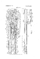
- FIG. 1 is a side elevational view partly in section and with'parts removed showing a presently preferred embodiment of the invention
- FIG. 2 is a partial side elevational view of the other tion, of a pump head assembly
- FIG. 9 is an enlarged side elevational view, partly in section, of the storage chamber and release valve body assembly
- FIG. 10 is an enlarged bottom view of the bolt and bolt handle assembly.
- FIG. 11 is an enlarged cross-sectional view of the air supply system.
- A. Receiver Assembly The gun mechanism is housed in a metallic receiver assembly 10 comprising nested receiver halves 12, 14 held together by suitable fastening devices 16, I8 and providing an elongated mechanism enclosure 19 having a generally rectangular cross-sectional configuration.
- a circular barrel opening 20 and a square pump housing opening 22 are provided in a front wall 24 of the receiver assembly located rearwardly of a forwardly facing recess 26 provided by a rim 28.
- a bottom wall 30 extends forwardly a substantial distance to provide an elongated support surface 32.
- a bolt handle opening 34 is provided on one side of the receiver assembly, as shown in FIGS. 2 and 10.
- a tapered access opening 36 is located forwardly of the bolt handle opening.
- Another access opening 38 may be provided on the opposite side, as seen in FIG. 3.
- a trigger opening 40, FIG. 4 is provided at the bottom of the receiver assembly and suitable stock attachment means are provided at the rear.
- a pair of bolt guideway ribs 42, 44, FIG. 4, and a number of support ribs 46, 48, 50, FIG. 3, are provided on opposite sides of the receiver assembly.
- a pair of inwardly inclined flanges 54, 56 define a downwardly opening pumping lever recess 58, FIG. 3.
- a pump assembly housing 60 extends within and forwardly of the receiver assembly through opening 22.
- the central portion of the housing has a square crosssectional configuration, FIG. 3, and is supported on the bottom wall of the receiver assembly between the inwardly extending ribs 46, 48, 50 in spaced relationship
- the upper wall of the housing terminates at 63, FIG. 1,
- valve housing slot 64 FIG. 4, extending rearwardly therefrom.
- the bottom wall of the housing is provided with a trigger slot 66, FIG. 1, ofsuitable size and shape.
- a downwardly opening linkage slot 68, FIGS. 5 and 6, is provided at the front end of the housing between opposite inwardly extending flange portions 70,72, which also provide roller trackways defined by inner side surfaces 74, 75, 76 and 77, 78, 79, respectively, FIG. 5.
- the housing fixedly supports an elongated tubular cylinder member 80 mounted therewithin.
- a cylindrical block 82 is fixedly mounted intermediate the ends of the cylinder with-a curved shoulder 84 abutting a semi-circular rib 86, FIG. 9, defined by a radially inwardly deformed portion 87 of the cylinder wall.
- valve block 88 has a cylindrical nose portion 89 closely fitted within the rear end of the cylinder.
- An upwardly extending rib 90, FIG. 1 l, is located within corresponding slot portions 64, 91, FIG. 11, of the housing and the cylinder, respectively.
- a longitudinally extending flange portion 92 abuts an upwardly rearwardly inclined B-B feed track (not shown) extending from the 8-3 storage chamber 61, adjacent a transverse deflection plate 94 forming the rear end wall of the storage chamber and mounted in a slot 95 in the flange portion, to a 8-8 feed opening (not shown) located behind the rear end of the barrel.
- the rear portion 99, FIG. 9, of the block is channelshaped with an upper wall 7 providing a bolt slide surface 102 and a rearwardly facing bolt abutment surface 104.
- the bottom surfaces of the inwardly extending ribs 42, 44, and side surfaces 105, 106 on opposite side walls of the receiver assembly are cooperatively arranged relative to the slide surface 102 to define an elongated bolt guideway 109 as shown in FIG. 4.
- Downwardly extending side walls 107, 108 on the rear portion of the block are nested within adjacent parallel side walls 110, 112 of the housing, as shown in FIG. 4, to define an enclosure 113 for the firing mechanism.
- the receiver assembly, housing, cylinder and valve block are relatively fixed by a pin 114 and a screw 116, FIG. 1.
- a tubular barrel 118 having a bore 120 extends through receiver assembly opening 20 and is provided with a notch 122, FIG. 11, cooperable with block rib 90 to locate the rear end of the barrel on the valve assembly.
- the front end of the barrel is supported in a front sight member 124 fixed on the forward end of a shroud member 126 supported on housing 60 by flange portions 128, 130, FIG. 7.
- the rear end of the shroud is received beneath the rim 28 of the receiver assembly and a rear sight assembly 131 is fixed on the shroud.
- a downwardly opening linkage slot 136 is provided between the bottom ends of the forearm members opposite the housing slot 68, FIG. 6.
- Areciprocal pump assembly 140 movable between an extended position, shown in FIGS. 1 and 8, and a retracted position (not shown) is connected by linkage means 142 to a pivotally mounted pumping lever 144 for compression of air in a variable volume compression chamber 145, FIG. 9, defined by the rear end wall 146, FIG. 8, of the pump assembly and the front wall 147 of the block 82.
- the pump assembly comprises a cylindrical piston member 148 and a hollow tubular piston rod member 150, FIG. I.
- a shaft portion 152 of the piston extends into the rear end of the rod and is attached thereto by a pin 154 fixed on the shaft portion and extending through opposite elongated slots 156 in opposite sides of the rod member to provide lost motion connecting means permitting limited sliding movement of the piston 148 relative to the rod 150 as hereinafter further described.
- a curved shoulder 158 is provided on the rear end ofthe piston to cooperatively receive the front portion of the rib 86 in a fully rearwardly extended position of the piston. as shown in FIGS. 1 and 8.
- An ring type sealing member 160 is mounted in a groove 162 on the periphery of the piston.
- a resilient compressible and expandable piston positioning means in the form of an elastomeric annulus 164 is compressibly mounted circumjacent shaft portion 152 between a forwardly facing abutment surface 166 and an abutment washer 168 held directly against the rear end of the rod, as shown in FIGS. 1 and 8.
- a lubricating felt washer 170 is also mounted circumjacent the shaft portion 152.
- the elastomeric annulus acts as a spring to normally fully rearwardly extend the piston relative to the rod with pin'154 rearwardly located in slots 156.
- the elastomeric annulus also acts as a resilient cushion permitting the piston to be moved forwardly relative to the rod with pin I54 moving toward the forward ends of the opposite elongated slots 156.
- the piston assembly is reciprocably operable in the cylinder by means ofa channel-shaped drag link 190 having rear end flange portions 194, 196, FIG. 7, pivotally attached to pin 176 and front end flange portions 198, 200, FIG. 5, pivotally attached to a pin 202 mounted between flange portions 204, 206, FIG. 6, of a channel-shaped actuating lever member 207 pivoted on the forward end of the housing by a pin 208.
- a plastic retainer sleeve 209 may be mounted between the flanges 198, 200 about pin 202.
- a plastic guide and enclosure rim 210, FIG. 6, is mounted on the pin 208 between and about the flanges 204, 206.
- An operating handle 211 is attached by suitable fastening means 212 to the rear of the actuating lever member 207 which has a channel-shaped reinforcing member 214.
- a compressed air storage chamber 216 is provided between the cylinder block 82 and the valve block 88.
- Axially extending ribs 224, 226 on the member 218 are compressed between the side surfaces 232, 234 of the block rims.
- An air inlet passage 236 in block 82 connects the variable volume air chamber in front of the block to the storage chamber 216 through a conical valve seat 238 in a rearwardly extending hub portion 240.
- a check valve 242 in the form of a forwardly projecting cylinder is integrally connected to and supported on the rearwardportion of rim 220 by forwardly extending resilient flexible flanges 244, 246, FIG. 3, and has a semi-spherical nose portion 248, FIG. I], cooperable with the valve seat 238 to close passage 236.
- High pressure compressed air in passage 236 will temporarily unseat the valve 242 to permit flow of air to the storage chamber 216 during a compression stroke while high pressure air in the storage chamber will reseat the valve, as soon as pressure equalization occurs, due to the resilience of the support flanges 244, 246 and the force of the high pressure air in the storage chamber acting forwardly against the rear surface 250 of the support flanges.
- the rear portion of the storage chamber is formed in the front of valve block 88 by a chamber 254, FIG. 11, which terminates rearwardly in an upwardly slanting relative narrow passage 256 of generally rectangular cross-sectional configuration having a pair of opposite parallel forwardly inclined surfaces 258, 260.
- Air passage means in the form of a compressed air outlet passage 262 extends at right angles to surface 258 and communicates with an inlet passage 264 in the rear end of the barrel through a compressible sealing washer 266 held in compression between adjacent outer peripheral surfaces of the valve block and the barrel.
- an air release valve means 268 is reciprocably supported in a valve plug 270 threadably mounted in a valve bore 272 in block 88 opposite the air outlet passage 262.
- the release valve comprises a head portion 274 having a conical tapered outer surface 276, adapted to sealingly engage a valve seat 278 circumjacent passage 262, and terminating in a flat pressure applying surface 280 for a purpose to be hereinafter described.
- a cylindrical rim portion 282 guides the valve in a bore 284 in the valve plug 270 and seats one end of a compression spring 286 by which the valve is biased to a closed position relative to passage 262.
- a reduced diameter valve portion supports the compression spring.
- a stem portion 290 extends through suitable sealing means such as a V-shaped sealing washer 292 of low density polyethylene material or the like, through correspondingly shaped washer seating rings 294, 296, of Delrin material or the like, and through a plugbore 298 of reduced diameter.
- suitable sealing means such as a V-shaped sealing washer 292 of low density polyethylene material or the like, through correspondingly shaped washer seating rings 294, 296, of Delrin material or the like, and through a plugbore 298 of reduced diameter.
- Spring 286 compressibly retains the washer 292 and valve ring 294, 296 against each other and a tapered seat 299 at the bottom of bore 284.
- the lower end of the valve is operably connected to operating means in the form of a control lever 300 by cam type lost motion connecting means comprising a washer 302 fixed to the valve stem.
- cam type lost motion connecting means comprising a washer 302 fixed to the valve stem.
- a curved cam surface 304 on the bottom of a bifurcated finger portion 306 of the control lever engages the upper surface 308 of the washer to positively cam the valve downwardly to the open position While otherwise permitting relative movement between the valve stem and the control lever.
- the control lever 300 is centrally pivoted on a pin 310, mounted between flange portions 107, 108 of block 88, for pivotal movement between a cocked, valve closed, position, FIG. 1, and a released, valve open, position, FIG. 11.
- valve head 274 is moved off the valve seat 278 to permit'high pressure air in the storage chamber to flow through passages 262, 264 to the barrel bore to fire a conventional pellet 311 or B-B 312 from the gun.
- high pressure air acts on valve end surface 280 to exert a valve opening force thereagainst whereby the valve is opened quickly and held open until the high pressure air has escaped from the storage chamber to fire the pellet from the gun.
- the spring 286 is effective to close the valve and to hold the valve closed until subsequently released by the control lever 300.
- the air release valve 268 and control lever 300 are operable by rearward pivotal movement of a trigger member 313 pivoted on block 88 by a pin 314.
- Latch and release means in the form of an upwardly extending latch finger 316 terminates in a curved cam surface 318 and has a generally downwardly facing latch surface 320 engageable with an abutment surface 322 on a latch lug 324 on the rear portion 325 of the control lever to releasably hold the control lever in a cocked t firing position, against the bias ofa compression spring 326 seated on opposite aligned projections 328, 330 between rear end portions of the trigger and the control lever, with transverse surfaces 332, 334 also in abutting engagement.
- a curved cam surface 340 on the top of the rear portion of the control lever is engageable by the rear end 342 of manually operable bolt means in the form of a slidable bolt member 344 to recock the'trigger and control lever by forcing the rear end of the control lever downwardly against the bias of the compression spring 326 with lug 324 engaging curved cam surface 318 and forcing the latch finger forwardly until the lug clears surface 318 whereupon the spring will move the latch finger rearwardly over and into abutting engagement with the lug along surfaces 320, 322, 332, 334 to hold the trigger and control lever in the cocked position.
- a safety mechanism is provided by selective abutting engagement between a manually slidable member 346 and a flange portion 348 of the trigger as shown in FIG. 1.
- the bolt member 344 comprises a generally hollow body portion 350 of generally rectangular peripheral configuration and a forwardly extending cylindrical portion 352 integrally formed of molded plastic material such as Delrin or the like.
- the body portion has a continuous upper rim comprising spaced parallel side walls 356, 358 and end walls 360, 362.
- the upper surfaces 364, 366 of the side walls slidably engage the lower surfaces of the ribs 42, 44 and the side surfaces 368, 370 slidably engage the inner side surfaces 105, 106 of the receiver halves 12, 14.
- a central transverse flange 372 extends between the side walls 356, 358 and the end walls 360, 362, and defines a bolt handle cavity 373 therebelow.
- the bottom portion 374 of side wall 358 and a portion 376 of the rear end wall 362 extend below the flange 372 to slidably engage the upper surface 102 of the valve block.
- An integral resilient deflectable spring finger 378 extends diagonally inwardly from the end of the rear wall portion 376 and terminates in a nose portion 380 having a rounded cam surface 382 engaging a plastic handle member 384 pivotally mounted in cavity 373 on a downwardly extending pin 386 integral with the bolt body portion.
- the upper handle surface 388 slidably engages the bottom surface 390 of the flange 372 and the bottom handle surface 392 slidably engages the valve block upper surface 102.
- the bolt member is slidably supported on the valve block surface 102 for sliding movement between a forwardly extended firing position, FIG. 1, and a rearwardly retracted loading and cocking position (not shown), by the bottom surfaces of wall portions 374, 376, the bottom surface of the front wall portion 360, the bottom surface of the spring finger 378, and the bottom surface 392, of the handle member 384.
- An actuating lever portion 393 of the handle member extends laterally outwardly from the pivotal connection beyond the handle cavity 373 through handle slot 34 in the receiver half 12 and terminates in a finger gripping portion 394 by which the bolt and the bolt handle may be manually pivotally manipulated between a latching position, FIG. 10, and a release position (not shown).
- a latching finger portion 395 of the handle extends longitudinally and laterally rearwardly from the pivotal connection and terminates in a latching notch 396.
- a handle locating abutment surface 397 is engageable with the adjacent inner side surface 105 of the receiver rearwardly adjacent the slot 34 to limit pivotal outward movement of the bolt handle.
- An inclined bolt holding abutment surface 398 extends outwardly from surface 397 and releasably engages the rear edge 400 of the slot 34 to latch the bolt in the forward firing position.
- the inner side surface 402 of the bolt handle extends diagonally inwardly into the bolt handle cavity to slidably engage and resiliently inwardly deflect the spring finger 378 to thereby resiliently continuously bias the bolt handle toward the latching position.
- the outer side surface 404 of the bolt handle is slidably engageable with the rear edge of the slot 34 to permit inward pivotal movement of the handle from the latched firing position to the release position permitting rearward movement of the bolt from the firing position to the loading
- Cylindrical portion 352 is centrally located relative to the body portion and extends forwardly from the front wall thereof in axial alignment with the barrel bore 120.
- a magnetic pin 414 is fixedly mounted in a bore 416 in the front of the bolt to position a pellet 311 or B8 312 in the firing position as shown in FIG. 11.
- pumping lever handle 211 is-grasped and pulled outwardly from the stowed position of FIG. 1.
- the pumping lever 144 is pivoted about pin 208 and pulls drag link 190 forwardly and downwardly to move pivot pin 176 longitudinally along the track in housing 60 on rollers 172, 174.
- the piston rod 150 and piston 140 are pulled forwardly to a retracted position (not shown) providing maximum volume in the compression chamber 145. Reverse movement ofthe lever from the extended position to the retracted position moves the piston member through an air compression stroke from the retracted position of maximum chamber volume to the extended position of minimum chamber volume.
- the piston of the present design will always bottom on the block member 82 without jamming, regardless of manufacturing tolerances, because ofthe lost motion connection means between the piston and the piston rod, which is provided by the pin 154 and elongated slots 156, and the spring-cushion effect of the elastomeric annulus 164, which extends the piston into abutting engagement with the surface 147.
- the volume of the compression chamber 145 is reduced to a minimum on each stroke to obtain higher compression of the air with a minimum of effort.
- High pressure air is forced from the compression chamber through passage 236 against check valve 242 and forces the check valve rearwardly by resilient deflection of the support flanges 244, 246 integrally connecting the valve to the rim portion 220 which is compressibly held between block rims 221, 222 to seal the air storage chamber 216 therebetween.
- the resilience of the valve supporting flanges and high pressure air in the storage chamber 216 acting thereagainst move the valve back onto the valve seat 238 to hold the high pressure air in the storage chamber.
- Several compression strokes may be utilized to build a desired level of pressure in the storage chamber.
- the handle 384 on the bolt 344 is grasped and pulled rearwardly to a retracted cocking and load position (not shown).
- the arrangement of the handle is such that the handle first pivots inwardly to clear the abutment surface 398 relative to the edge 400 of the receiver slot 34 and then moves rearwardly along surface to the retracted position.
- the rear wall 362 of the body portion will engage the cam surface 340 of the control lever 300, if the gun is uncocked, and force down the rear portion of the control lever by pivotal movement about pin 310.
- the cylindrical bolt portion 352 In the retracted cocking and loading position, the cylindrical bolt portion 352 is moved rearwardly to clear the rear end of the barrel, loading slot 36 and B-B opening 96. A pellet or 8-8 may then be loaded into the rear end of the barrel through the slot 36 or the opening 96.
- the bolt is then manually moved forwardly to an extended firing position, FIG. 1, with the magnetic pin on the front of the cylindrical bolt portion pushing the B-B or hollow pellet into firing position with the sealing lip 406 entering the tapered barrel shoulder 412 to engage and seal the end of the bore.
- the bolt handle In the forward firing position, the bolt handle is pivotally outwardly biased by spring finger 378 to seat the handlelatch surface 398 against the receiver slot abutment surface 400 and prevent rearward movement of the bolt.
- Pivotal movement of the control lever 300 to the firing position pulls the release valve 268 open against the bias ofcompression spring 286, FlG. 11, due to engagement between cam surface 304 on the bottom of the end of the control lever actuating finger and the upper surface 308 on the abutment washer 302 attached to the valve stem.
- high pressure air in the storage chamber 216 rushes into outlet passage 262 and exerts a rear ward force on the valve head upper end surface to maintain the valve open against the bias of compression spring 286 until the pressure of the air in the storage chamber is reduced and the pellet has been fired by passage of the air into the barrel bore behind the pellet through inlet passage 264.
- a gas operated gun having a barrel through which a projectile is fired from a firing chamber by high pressure gas, the invention comprising:
- a slidable bolt member of one piece plastic material slidably movable between a forwardly extended firing position and a rearwardly retracted loading position
- a slidable bolt member of one piece plastic material slidably movable between a forwardly extended firing position and a rearwardly retracted loading position
- a body portion of said bolt. member slidably supported on said trackway and being of generally polygonal box-like peripheral configuration, said I body portion having a handle cavity therein, and a bolt operating handle mounted in said handle cavity and carried by and operatively connected to said bolt member, said bolt operating handle being movable between a latching position and an operation position relative to said bolt member, a spring between said bolt member and said handle effective to bias said handle toward the latching position and to hold said bolt member in the forwardly extended firing position until actuation of said handle from the latching position to the operating positlOll;
- a handle slot in said gun opposite said trackway said handle extending through and beyond said slot for manual manipulation of said bolt member, said handle having a latch surface engageable with said gun adjacent said slot in the latching position to hold said bolt member in the forwardly extended firing position and disengageable from said gun adjacent said slot by inward pivotal movement of said handle relative to said gun and said body portion to permit movement of said handle and said body portion along said trackway and said slot between the forwardly extended firing position and the rearwardly retracted loading position, and
- a finger portion of said bolt member being aligned with said firing chamber and extending forwardly from said body portion theretoward.
- elongated housing means having a generallypolygonal transverse cross sectional configuration defined by internal surfaces of said housing means
- an elongated bolt guideway located within said housing rearwardly of the firing chamber and defined by portions of said internal surfaces and having a generally polygonal transverse cross sectional configuration
- an elongated bolt member having a body portion of generally polygonal cross sectional configuration slidably mounted in said guideway for movement between a forwardly extended firing position and a rearwardly retracted loading position
- projectile engaging means on the forward end of said finger portion and operatively movable therewith for moving a projectile into the firing chamber to position the projectile therewithin prior to actuation of said operating means.
- said slidable bolt member is made from a one piece molded plastic material.
- said handle extending through and beyond said slot for manual manipulation of said bolt member.
Landscapes
- Engineering & Computer Science (AREA)
- General Engineering & Computer Science (AREA)
- Portable Nailing Machines And Staplers (AREA)
- Toys (AREA)
- Investigating Or Analysing Materials By Optical Means (AREA)
Priority Applications (5)
| Application Number | Priority Date | Filing Date | Title |
|---|---|---|---|
| US00263628A US3810455A (en) | 1972-06-16 | 1972-06-16 | Pneumatic gun with polygonal cross-section bolt member |
| CA169,786A CA972646A (en) | 1972-06-16 | 1973-04-30 | Pneumatic gun |
| GB2573073A GB1381568A (en) | 1972-06-16 | 1973-05-30 | Gas operated gun |
| JP6676073A JPS5246437B2 (Direct) | 1972-06-16 | 1973-06-13 | |
| DE19732330534 DE2330534C3 (de) | 1972-06-16 | 1973-06-15 | Ladeeinrichtung für eine DruckgasschuBwafte |
Applications Claiming Priority (1)
| Application Number | Priority Date | Filing Date | Title |
|---|---|---|---|
| US00263628A US3810455A (en) | 1972-06-16 | 1972-06-16 | Pneumatic gun with polygonal cross-section bolt member |
Publications (1)
| Publication Number | Publication Date |
|---|---|
| US3810455A true US3810455A (en) | 1974-05-14 |
Family
ID=23002566
Family Applications (1)
| Application Number | Title | Priority Date | Filing Date |
|---|---|---|---|
| US00263628A Expired - Lifetime US3810455A (en) | 1972-06-16 | 1972-06-16 | Pneumatic gun with polygonal cross-section bolt member |
Country Status (4)
| Country | Link |
|---|---|
| US (1) | US3810455A (Direct) |
| JP (1) | JPS5246437B2 (Direct) |
| CA (1) | CA972646A (Direct) |
| GB (1) | GB1381568A (Direct) |
Cited By (6)
| Publication number | Priority date | Publication date | Assignee | Title |
|---|---|---|---|---|
| US5363834A (en) * | 1993-03-30 | 1994-11-15 | Daisy Manufacturing Company, Inc. | Gun powered by either compressed gas cartridge or hand-pumped air |
| US6343598B1 (en) * | 1999-11-30 | 2002-02-05 | Valery Pshenychny | Air gun |
| US20050016514A1 (en) * | 2003-07-09 | 2005-01-27 | Nadel Network, Llc | Projectile launcher including audiovisual stimuli |
| US20120125305A1 (en) * | 2009-06-16 | 2012-05-24 | Yigit Zafer | High-power pneumatic weapon system |
| US20150053194A1 (en) * | 2013-08-21 | 2015-02-26 | Xilong LI | Air rifle |
| WO2015006597A3 (en) * | 2013-07-10 | 2015-03-12 | Inovairtech Llc | Compressed gas cartridge |
Citations (6)
| Publication number | Priority date | Publication date | Assignee | Title |
|---|---|---|---|---|
| US1512993A (en) * | 1922-05-05 | 1924-10-28 | Bertram S Fenner | Air gun |
| US2098137A (en) * | 1935-07-16 | 1937-11-02 | Elfstrom Otto | Rifle |
| US2435647A (en) * | 1945-02-21 | 1948-02-10 | Martin O Engseth | Grease gun |
| GB937658A (en) * | 1959-05-19 | 1963-09-25 | Birmingham Small Arms Co Ltd | Improvements in or relating to air guns |
| US3204625A (en) * | 1963-03-22 | 1965-09-07 | Bob G Shepherd | Gas-operated pistol |
| US3483793A (en) * | 1968-03-04 | 1969-12-16 | Olin Mathieson | Piston-rammer compression ignition assembly |
-
1972
- 1972-06-16 US US00263628A patent/US3810455A/en not_active Expired - Lifetime
-
1973
- 1973-04-30 CA CA169,786A patent/CA972646A/en not_active Expired
- 1973-05-30 GB GB2573073A patent/GB1381568A/en not_active Expired
- 1973-06-13 JP JP6676073A patent/JPS5246437B2/ja not_active Expired
Patent Citations (6)
| Publication number | Priority date | Publication date | Assignee | Title |
|---|---|---|---|---|
| US1512993A (en) * | 1922-05-05 | 1924-10-28 | Bertram S Fenner | Air gun |
| US2098137A (en) * | 1935-07-16 | 1937-11-02 | Elfstrom Otto | Rifle |
| US2435647A (en) * | 1945-02-21 | 1948-02-10 | Martin O Engseth | Grease gun |
| GB937658A (en) * | 1959-05-19 | 1963-09-25 | Birmingham Small Arms Co Ltd | Improvements in or relating to air guns |
| US3204625A (en) * | 1963-03-22 | 1965-09-07 | Bob G Shepherd | Gas-operated pistol |
| US3483793A (en) * | 1968-03-04 | 1969-12-16 | Olin Mathieson | Piston-rammer compression ignition assembly |
Cited By (8)
| Publication number | Priority date | Publication date | Assignee | Title |
|---|---|---|---|---|
| US5363834A (en) * | 1993-03-30 | 1994-11-15 | Daisy Manufacturing Company, Inc. | Gun powered by either compressed gas cartridge or hand-pumped air |
| US6343598B1 (en) * | 1999-11-30 | 2002-02-05 | Valery Pshenychny | Air gun |
| US20050016514A1 (en) * | 2003-07-09 | 2005-01-27 | Nadel Network, Llc | Projectile launcher including audiovisual stimuli |
| US20120125305A1 (en) * | 2009-06-16 | 2012-05-24 | Yigit Zafer | High-power pneumatic weapon system |
| US8905012B2 (en) * | 2009-06-16 | 2014-12-09 | Atak Silah Sanayi Ve Ticaret Limited Sirketti | High-power pneumatic weapon system |
| WO2015006597A3 (en) * | 2013-07-10 | 2015-03-12 | Inovairtech Llc | Compressed gas cartridge |
| US20150053194A1 (en) * | 2013-08-21 | 2015-02-26 | Xilong LI | Air rifle |
| US9267757B2 (en) * | 2013-08-21 | 2016-02-23 | Nanjing Airgun Manufacturing Ltd. | Air rifle |
Also Published As
| Publication number | Publication date |
|---|---|
| DE2330534B2 (de) | 1976-06-24 |
| JPS4950793A (Direct) | 1974-05-17 |
| DE2330534A1 (de) | 1974-01-03 |
| CA972646A (en) | 1975-08-12 |
| JPS5246437B2 (Direct) | 1977-11-24 |
| GB1381568A (en) | 1975-01-22 |
Similar Documents
| Publication | Publication Date | Title |
|---|---|---|
| US5339791A (en) | Gas powered gun | |
| US5363834A (en) | Gun powered by either compressed gas cartridge or hand-pumped air | |
| US5509399A (en) | Semi-automatic fluid powered gun | |
| US5791328A (en) | Air valve for marking pellet gun | |
| US7481209B1 (en) | Toy projectile launcher with slidable outer cylinder and stationary inner compression member | |
| US3788298A (en) | Compressed gas gun with trigger operated hammer release latching structure | |
| US5377436A (en) | Cartridge clip reloader | |
| KR0140831B1 (ko) | 자동 탄환 공급 기구를 가진 장난감 총 | |
| US3763843A (en) | Pneumatic gun | |
| US6119671A (en) | Toy projectile launcher | |
| US8201547B2 (en) | Bolt and valve mechanism that uses less gas | |
| US20030047175A1 (en) | Pneumatic gun | |
| US4038961A (en) | Pneumatic rifle and hand gun | |
| US2725869A (en) | Magazine toy gun | |
| US3810455A (en) | Pneumatic gun with polygonal cross-section bolt member | |
| US5161516A (en) | Compressed gas gun | |
| US4002156A (en) | Air gun | |
| US3908626A (en) | Air gun mechanism arrangement | |
| US3802408A (en) | Pneumatic gun with valve operating mechanism | |
| US3800773A (en) | Pneumatic gun with lost motion piston-piston rod connection | |
| US5701879A (en) | Compressed air gun with single action pump | |
| US2673557A (en) | Pneumatic gun | |
| US3212490A (en) | Air gun | |
| US5913304A (en) | Compressed air gun with temporary seal | |
| GB1177326A (en) | Air Gun and Projectile |
Legal Events
| Date | Code | Title | Description |
|---|---|---|---|
| AS | Assignment |
Owner name: KIDDE RECREATION PRODUCTS, INC. 3900 NORTH ROCKWEL Free format text: ASSIGNMENT OF ASSIGNORS INTEREST.;ASSIGNOR:VICTOR UNITED INC., A DE CORP.;REEL/FRAME:004222/0568 Effective date: 19830715 |
|
| AS | Assignment |
Owner name: REPUBLICBANK DALLAS, NATIONAL ASSOCIATION Free format text: SECURITY INTEREST;ASSIGNOR:DAISY MANUFACTURING COMPANY, INC.;REEL/FRAME:004225/0076 Effective date: 19830128 |
|
| AS | Assignment |
Owner name: DAISY MANUFACTURING COMPANY, INC., ROGER, AR., A D Free format text: ASSIGNMENT OF ASSIGNORS INTEREST.;ASSIGNOR:KIDDE RECREATION PRODUCTS, INC.;REEL/FRAME:004245/0125 Effective date: 19831115 |
|
| AS | Assignment |
Owner name: SPBC, INC. A DE CORPORATION, CALIFORNIA Free format text: SECURITY INTEREST;ASSIGNOR:DAISY MANUFACTURING COMPANY, INC., A DE CORPORATION;REEL/FRAME:005810/0669 Effective date: 19910802 |