US3807208A - Interstand tension-compression control system - Google Patents
Interstand tension-compression control system Download PDFInfo
- Publication number
- US3807208A US3807208A US00276490A US27649072A US3807208A US 3807208 A US3807208 A US 3807208A US 00276490 A US00276490 A US 00276490A US 27649072 A US27649072 A US 27649072A US 3807208 A US3807208 A US 3807208A
- Authority
- US
- United States
- Prior art keywords
- stand
- motor
- signal
- summation
- speed
- Prior art date
- Legal status (The legal status is an assumption and is not a legal conclusion. Google has not performed a legal analysis and makes no representation as to the accuracy of the status listed.)
- Expired - Lifetime
Links
Images

Classifications
-
- B—PERFORMING OPERATIONS; TRANSPORTING
- B21—MECHANICAL METAL-WORKING WITHOUT ESSENTIALLY REMOVING MATERIAL; PUNCHING METAL
- B21B—ROLLING OF METAL
- B21B37/00—Control devices or methods specially adapted for metal-rolling mills or the work produced thereby
- B21B37/48—Tension control; Compression control
- B21B37/52—Tension control; Compression control by drive motor control
Definitions
- a system for controlling interstand tension and compression in a continuous rolling mill having a plurality of stands.
- Each stand has an electrical motor for actuating the rollers for successively rolling material to a predetermined crosssectional area.
- Means are provided for detecting the entrance of the material into the first stand rollers, and for developing a first load detecting signal.
- First delay means actuated in response to the first load detecting signal, deliver a first delay signal after a predetermined time delay.
- Means actuated in response to the first delay signal are provided for memorizing the armature current Ialm of the first stand motor.
- Seconddelay means are provided for detecting the presence of the material in the succeeding second stand rollers for delivery'of a second load detecting signal.
- Means, actuated in response to the second load detecting signal are provided for comparing the instantaneous armature current Ial of the first motor with the armature current Ialm held in memory and for delivering a polarized compared signal. Then, means actuated in response to the polarized compared signal, increase ordecrease the speed of the second motor until the compared signal is zero, i.e.'
- the interstand tension-compression control system of the invention is here illustrated in the environment of a bar or billet mill. 'Usually such a mill will include roughing, intermediate and finishing sections.
- the roughing mill may comprise six stands, the intermediate mill four stands, and the finishing mill may have as many as six stands.
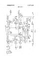
- FIG. 1 only two stands 10, 12 are shown, although it will be obvious from the description that the system is readily expandable to include as many stands as desired.
- the l0, l2 stands respectively comprises rollers indicated symbolically at 14, 16 coupled through gearing 18, 20 to electric motors (usually a DC. shunt motor) indicated at 22, 24.
- the stand motors 22, 24 are connected to a common bus 26.
- the motor 22 has a shunt field 28 which is connected to a field exciter and speed regulator indicated symbolically by the box identified at 30. (The corresponding components for motor 24 are identified at 32 and 34).
- a tachometer generator 36 is coupled to the shaft of motor 22.
- tachometer generator 38 is coupled to the shaft of motor 24.
- Shunt resistors at 40, 42 enable the armature currents of motors 22 and 24 to be monitored, the armature currents being applied to amplifiers 44, 46 respectively as shown.
- a load detecting means for STAND ONE is indicated generally at 48.
- a load detecting means for STAND TWO is indicated generally at-50.
- the load detecting means 48 comprises: the tachometer generator previously identified at 36, a summation amplifier 52, a capacitor 54 and a relay lLD having normally open contacts lLDl.
- the scheme for identifying the various relays is as follows:
- the prefix indicates the stand number with which the relay is associated.
- the letters will, wherever possible give an indication of the function to be performed by the relay i.e., LD is load detecting.
- the numeration following the letters indicates the identification of the contacts. A bar under the numeral indicates that the contacts are normally closed, while no bar indicates that they are normally open.
- the second stand load detecting means 50 comprises the tachometer generator previously identified at 38, a
- the speed changing means for STAND ONE and STAND TWO are identified at 60 and 62 respectively.
- the speed changing means 60 comprises an amplifier 64 which drives a motor-potentiometer 66,68.
- a motor operated potentiometer of this kind is well known in the art e the motor drives the slider of the potentiometer so that the slider picks of a voltage, the potentiometer being connected between a source of potential (here the master speed reference) and ground.
- a manual speed adjustment input provides a voltage signal input which determines the initial positioning of the respective slides of the potentiometers.
- the speed adjusting means 62 is similar to the speed adjusting means 60, and comprises amplifier 70, and motor-potentiometer 72,74, the only difference being that amplifier 70 has an additional input which is applied through contacts 2LD2. In this respect all the succeeding STANDS THREE, FOUR ect. will be similar to STAND TWO.
- a memory means for STAND ONE is identified generally at 76.
- the memory means 76 comprises an amplifier 78, the output of which is applied through contacts lCRl to an operational amplifier indicated generally at 80, connected as an integrator.
- the operational amplifier 80 comprises resistor 82, amplifier 84 and feedback capacitor 86. The output of the operational amplifier 80 is fed back to the input of amplifier 78 and to a summation amplifier 88 associated withSTAND TWO.
- a transport delay means for STAND ONE is identified generally at 90, and comprises an operational amplifier 92 operated as an integrator, and a voltage comparator 94.
- the operational amplifier 92 includes an input resistor 96 applied to an amplifier 98 having a capacitor 100 in the feedback loop.
- the voltage comparator 94 includes an amplifier 102 which receives one input from the operational amplifier 92, the other input being connected to the slider of a potentiometer 104 which isconnected between a source of negative potential and ground as indicated.
- the operator selects the Automatic Stand Speed Set (A pushbutton to initiate the interstand tension system) of the instant invention.
- a bar or billet from the heating furnace now enters STAND ONE.
- the current from themotor 22 passes through-the shunt 40 to the amplifier 44'.
- the output Ial (the armature current of themotor of STAND ONE) of amplifier 44 is applied: to the summing amplifier 52, to the amplifier 78 and to the summation amplifier 88.
- the output of the tachometer generator 36 is connected to the input of amplifier 52 through capacitor 54. This output is also connected to the speed transport delay means 90.
- the load detector detects when the billet is in STAND ONE: thus, during acceleration 'or deceleration, the change in voltage results in a voltage at the capacitive input of amplifier 52 which is equal and opposite to the voltage at the other input, and relay lLD remains inactivated. However, the load torque required to roll the billet results in an increase in the motor armature current Ial, the resulting unbalance producing output signal at the output of amplifier 52 which actuates the relay lLD.
- the closing of normally open contacts lLDl electrically completes the circuit for both relays 1CR and ISTD.
- the relay contacts lCRl and 1STD1 close simultaneously actuating the memory means 76 and the first transport
- the billet transport delay means 90 is intended to cease operation or to be deactivated when the billet is about to enter STAND TWO.
- the memory means 76 then retains a voltage which is a function of the current Ialm, which in turn is a function of the actual load torque required to roll the billet.
- the input lalm is applied to the amplifier 78; the output of the amplifier 78 is applied through now closed contacts lCRl to the integrator 80.
- the amplifier 84 acts as an inverter, and the output Ialm' is negative.
- the integrator by virtue of the charged camoving from STAND ONE to STAND TWO.
- the relay ITD is actuated, causing normally closed contact lTDl to open;
- motor 24 will have an effect on what is happening at STAND ONE. Obviously, as motor 24 pulls less on the billet tension will decrease, and lal will increase until it equals lalm.
- the condition Ial lalm is further depicted in FIG. 2.
- the curve A represents the armature current without correction; curve B represents the armature current in the practice of the invention.
- condition lal lalm is depicted in FIG. 3. Similarly the system at t4 begins to look at the error due to compression and make correction.
- the mill operator can then turn off the automatic stand speed set and proceed to continuously roll billets.
- An interstandtension-compression control system for use in a continuous mill having a plurality of stands
- each stand having an electric motor for actuating rollers for successively rolling material to a predetermined cross sectional area
- each stand having an electric motor for actuating rollers for successively rolling material to a predetermined cross sectional area
- first detecting means for sensing the presence of said material in the first stand rollers and for developing a first load detecting signal
- memory means actuated in response to said first load detecting signal and connected to receive the armature current lal of the first stand motor, for
- first transport delay means actuated in response to said first load detecting signal, and arranged to receive a first voltage proportional to the speed of said first motor, and to deliver a first transport delay signal which is an inverse function of the first motor speed, said first transport delay signal inactivating said memory means, said latter means retaining the memorized armature current lalm;
- second detecting means for sensing the presence of said material in the succeeding second stand rollers, and for developing a second load detecting signal;
- algebraic summation means actuated in response to said second load detecting signal and adapted to receive the polarized instantaneous armature current lal, of said first motor, and the polarized memorized armature current lalm, and to deliver an algebraic summation signal which becomes zero when Ial lalm;
- second speed changing means actuated upon receipt of said second load detecting signal for increasing or decreasing the speed of the second stand motor, said second motor speed changing means being connected to receive said algebraic summation signal, and to change the speed of said second stand motor as a function of said algebraic summation signal; and second transport delay means actuated in response to said second load detecting signal, arranged to receive a second voltage proportional tothe speed of said second motor and to deliver a second transport delay signal which is an inverse function of the second motor speed, said second transport delay signal electrically isolating the first stand from the second stand, the material having now traversed from the first stand to the second stand under substantially no tensile or compressive stress.
- An interstand tension-compression control system for use in a continuous mill having a plurality of stands, each stand having an electric motor for actuating rollers for successively rolling material to a predetermined cross sectional area comprising, first detectingmeans for sensing the presence of said material in the first stand rollers and for developing a first load detecting signal, memory means actuated in response to said first load detecting signal .and connected to receive the armature current lal of the first stand motor, for memorizing the armature current lalm, first transport delay means actuated in responce to said first load detecting signal, and arranged to receive a first voltage proportional to the speed of said first motor, and to deliver a first transport delay signal which is an inverse function of thefirst motor speed, said first transport delay signal inactivating said memory means, said latter means retaining the memorized armature current Ialm, said first detecting means comprising summation means, means for deriving a signal which is a function of the instantaneous speed of said first motor, capaci
- An interstand tension-compression control system wherein said deriving means comprises a tachometer generator connected to the shaft of said first stand motor.
- said memory means comprises in series, a first summation amplifier, circuit interrupting means, and an operational amplifier connected as an integrator, said circuit interrupting means coupling said first summation amplifier and said operational amplifier, said first summation amplifier being adapted to receive as a first input said polarized instantaneous armature current la of said motor, and as a second input, the polarized feedback signal from the output of said operational amplifier, whereby the first transport delay signal actuates said circuit interrupter means to isolate said first summation amplifier from said operational amplifier, the output of said operational amplifier being 8 held at Ialm. l 5.
- said first transport delay means comprises in series, circuit interrupting means, an operational amplifier connected as an integrator, a first summation amplifier and relay means, said circuit interrupting means actuated in response to said first load detecting signal connecting said first voltage signal to said operational amplifier, the polarized output of said operational amplifier being connected as one input to said first summation amplifier, the other input of said first summation amplifier being a variable signal of a different polarity, said first summation amplifier delivering said first transport delay signal when said polarized signals are equal in magnitude.
- said speed changing means comprises an additional motor, a potentiometer, a common voltage source, saidpotentiometer being across said common voltage source and having a slider displaceable in response to the rotational displacement of said additional motor, the displacement of said slider providing an incremental or decremental voltage to the field of said second motor, said additional motor being actuated only upon receipt of said second load detecting signal, the rotational displacement of said motor being a function of said algebraic summation signal.
Landscapes
- Engineering & Computer Science (AREA)
- Mechanical Engineering (AREA)
- Control Of Metal Rolling (AREA)
Priority Applications (5)
| Application Number | Priority Date | Filing Date | Title |
|---|---|---|---|
| US00276490A US3807208A (en) | 1972-07-31 | 1972-07-31 | Interstand tension-compression control system |
| DE19732337830 DE2337830A1 (de) | 1972-07-31 | 1973-07-25 | Anordnung zum zug- und schubkraftfreien walzen von walzgut in einer mehrgeruestigen walzenstrasse |
| FR7327211A FR2194493B1 (OSRAM) | 1972-07-31 | 1973-07-25 | |
| CH1098773A CH566827A5 (OSRAM) | 1972-07-31 | 1973-07-27 | |
| AT668473A AT323844B (de) | 1972-07-31 | 1973-07-30 | Schaltungsanordnung zum zug- und schubkraftfreien walzen von walzgut in einer mehrgerüstigen walzenstrasse |
Applications Claiming Priority (1)
| Application Number | Priority Date | Filing Date | Title |
|---|---|---|---|
| US00276490A US3807208A (en) | 1972-07-31 | 1972-07-31 | Interstand tension-compression control system |
Publications (1)
| Publication Number | Publication Date |
|---|---|
| US3807208A true US3807208A (en) | 1974-04-30 |
Family
ID=23056854
Family Applications (1)
| Application Number | Title | Priority Date | Filing Date |
|---|---|---|---|
| US00276490A Expired - Lifetime US3807208A (en) | 1972-07-31 | 1972-07-31 | Interstand tension-compression control system |
Country Status (5)
| Country | Link |
|---|---|
| US (1) | US3807208A (OSRAM) |
| AT (1) | AT323844B (OSRAM) |
| CH (1) | CH566827A5 (OSRAM) |
| DE (1) | DE2337830A1 (OSRAM) |
| FR (1) | FR2194493B1 (OSRAM) |
Cited By (8)
| Publication number | Priority date | Publication date | Assignee | Title |
|---|---|---|---|---|
| JPS50102787A (OSRAM) * | 1974-01-21 | 1975-08-14 | ||
| US3940960A (en) * | 1974-01-21 | 1976-03-02 | Hitachi, Ltd. | Interstand tension control method and apparatus for tandem rolling mills |
| US4003230A (en) * | 1974-08-16 | 1977-01-18 | Hitachi, Ltd. | Tension control system for universal mill |
| US4137742A (en) * | 1977-01-07 | 1979-02-06 | Hitachi, Ltd. | Interstand tension control method and apparatus for tandem rolling mill |
| EP0004598A3 (en) * | 1978-04-10 | 1979-10-31 | Brown, Boveri & Cie Aktiengesellschaft Mannheim | Process and circuit for interstand tension control in a continuous rolling mill having individual drives |
| DE2834102A1 (de) * | 1978-08-03 | 1980-02-14 | Siemens Ag | Einrichtung zum kontinuierlichen walzen von walzgut in einer m gerueste enthaltenden walzstrasse |
| US4379395A (en) * | 1980-02-20 | 1983-04-12 | Hitachi, Ltd. | Interstand tension control system and method for tandem rolling mill |
| US5355060A (en) * | 1990-10-24 | 1994-10-11 | Aeg Automation Systems Corporation | Load impact controller for a speed regulator system |
Families Citing this family (3)
| Publication number | Priority date | Publication date | Assignee | Title |
|---|---|---|---|---|
| DE2541071C3 (de) * | 1975-09-15 | 1984-07-12 | Siemens AG, 1000 Berlin und 8000 München | Vorrichtung zur Regelung der im Walzgut übertragenen Zugkraft in einer mehrgerüstigen kontinuierlichen Walzstraße |
| FR2395086A1 (fr) * | 1977-06-24 | 1979-01-19 | Siderurgie Fse Inst Rech | Procede de controle de la tension de produits epais lamines a chaud en prise entre deux cages successives |
| RU2198753C1 (ru) * | 2002-03-22 | 2003-02-20 | Общество с ограниченной ответственностью "СЛОТ" | Способ задания скоростного режима непрерывной группы прокатных клетей стана горячей прокатки металла с обеспечением минимального натяжения в межклетевых промежутках |
Citations (3)
| Publication number | Priority date | Publication date | Assignee | Title |
|---|---|---|---|---|
| US3363441A (en) * | 1965-09-28 | 1968-01-16 | Westinghouse Electric Corp | Speed control system for edger and other rolls in a reduction rolling mill |
| US3688532A (en) * | 1970-11-24 | 1972-09-05 | Antonio Vicente Silva | Control system for tandem rolling mill based on the constant volume principle |
| US3695075A (en) * | 1970-06-11 | 1972-10-03 | Mitsubishi Electric Corp | Correction system for continuous rolling mill |
Family Cites Families (2)
| Publication number | Priority date | Publication date | Assignee | Title |
|---|---|---|---|---|
| GB989613A (en) * | 1960-07-05 | 1965-04-22 | Davy And United Instr Ltd | Improvements in or relating to automatic control systems |
| FR1376645A (fr) * | 1963-09-10 | 1964-10-31 | Siemag Siegener Masch Bau | Procédé et dispositif pour la régulation des cages d'un laminoir continu, en vue d'exercer une traction ou une pression constante, réglable, sur le produit de laminage |
-
1972
- 1972-07-31 US US00276490A patent/US3807208A/en not_active Expired - Lifetime
-
1973
- 1973-07-25 DE DE19732337830 patent/DE2337830A1/de active Pending
- 1973-07-25 FR FR7327211A patent/FR2194493B1/fr not_active Expired
- 1973-07-27 CH CH1098773A patent/CH566827A5/xx not_active IP Right Cessation
- 1973-07-30 AT AT668473A patent/AT323844B/de not_active IP Right Cessation
Patent Citations (3)
| Publication number | Priority date | Publication date | Assignee | Title |
|---|---|---|---|---|
| US3363441A (en) * | 1965-09-28 | 1968-01-16 | Westinghouse Electric Corp | Speed control system for edger and other rolls in a reduction rolling mill |
| US3695075A (en) * | 1970-06-11 | 1972-10-03 | Mitsubishi Electric Corp | Correction system for continuous rolling mill |
| US3688532A (en) * | 1970-11-24 | 1972-09-05 | Antonio Vicente Silva | Control system for tandem rolling mill based on the constant volume principle |
Cited By (8)
| Publication number | Priority date | Publication date | Assignee | Title |
|---|---|---|---|---|
| JPS50102787A (OSRAM) * | 1974-01-21 | 1975-08-14 | ||
| US3940960A (en) * | 1974-01-21 | 1976-03-02 | Hitachi, Ltd. | Interstand tension control method and apparatus for tandem rolling mills |
| US4003230A (en) * | 1974-08-16 | 1977-01-18 | Hitachi, Ltd. | Tension control system for universal mill |
| US4137742A (en) * | 1977-01-07 | 1979-02-06 | Hitachi, Ltd. | Interstand tension control method and apparatus for tandem rolling mill |
| EP0004598A3 (en) * | 1978-04-10 | 1979-10-31 | Brown, Boveri & Cie Aktiengesellschaft Mannheim | Process and circuit for interstand tension control in a continuous rolling mill having individual drives |
| DE2834102A1 (de) * | 1978-08-03 | 1980-02-14 | Siemens Ag | Einrichtung zum kontinuierlichen walzen von walzgut in einer m gerueste enthaltenden walzstrasse |
| US4379395A (en) * | 1980-02-20 | 1983-04-12 | Hitachi, Ltd. | Interstand tension control system and method for tandem rolling mill |
| US5355060A (en) * | 1990-10-24 | 1994-10-11 | Aeg Automation Systems Corporation | Load impact controller for a speed regulator system |
Also Published As
| Publication number | Publication date |
|---|---|
| DE2337830A1 (de) | 1974-02-14 |
| AT323844B (de) | 1975-07-25 |
| FR2194493A1 (OSRAM) | 1974-03-01 |
| CH566827A5 (OSRAM) | 1975-09-30 |
| FR2194493B1 (OSRAM) | 1978-01-06 |
Similar Documents
| Publication | Publication Date | Title |
|---|---|---|
| US3807208A (en) | Interstand tension-compression control system | |
| GB1142041A (en) | Slave gauge control system for a rolling mill | |
| GB982232A (en) | Improvements in or relating to automatic strip gauge control for a rolling mill | |
| GB1292845A (en) | Predictive gauge control method and apparatus with adaptive plasticity determination for metal rolling mills | |
| US4011743A (en) | Stand speed reference circuit for a continuous tandem rolling mill | |
| GB1248978A (en) | Predictive roll-force gauge control method and apparatus for metal rolling mills | |
| GB1259309A (OSRAM) | ||
| US3186200A (en) | Automatic thickness regulator for strip rolling mills | |
| GB1163274A (en) | Improvements in and relating to Rolling Mills | |
| US2601792A (en) | Apparatus for rolling strip material | |
| US3940960A (en) | Interstand tension control method and apparatus for tandem rolling mills | |
| GB841504A (en) | Improvements in or relating to electric motor control apparatus | |
| GB1013267A (en) | Method and apparatus for reducing the thickness of strip material | |
| US3029373A (en) | Motor speed control system | |
| US3186201A (en) | Production of metal strip | |
| US3540248A (en) | Speed control system for a rolling mill | |
| US3111046A (en) | Automatic control system for continuous strip mill | |
| US3762195A (en) | Thickness control apparatus for rolling mill | |
| US2590491A (en) | Control system | |
| US4016735A (en) | Range control for an automatic gauge control system of a rolling mill | |
| US3232084A (en) | Mill control systems | |
| GB1419814A (en) | Constant speed driven continuous rolling mill | |
| US3212310A (en) | Automatic gauge and tension control system | |
| US3109330A (en) | Continuous mill control means | |
| US3464245A (en) | Rolling mill having a controlled hydraulic prestress range and other gap adjusting means for initial operation and for adjustment to said range |
Legal Events
| Date | Code | Title | Description |
|---|---|---|---|
| AS | Assignment |
Owner name: AEG WESTINGHOUSE INDUSTRIAL AUTOMATION CORPORATION Free format text: ASSIGNMENT OF ASSIGNORS INTEREST.;ASSIGNOR:WESTINGHOUSE ELECTRIC CORPORATION;REEL/FRAME:005424/0551 Effective date: 19900313 |